D6NLOWFMMOD1V1FM Modulator
Navico Inc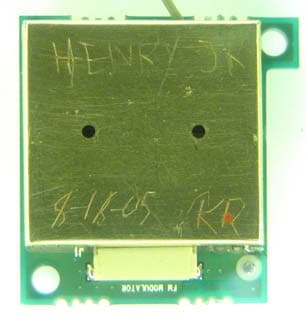
Click to zoom
Application Details
- Equipment Class
- DXT - Part 15 Low Power Transceiver, Rx Verified
- Date of Grant
- Sep 13, 2005
- Application Purpose
- Original Equipment
- Date of Application
- Sep 13, 2005
- Equipment Note
- FM Modulator
- Frequency Range
- 88.00000000 - 108.00000000
- Company
- Navico Inc
- Country
- United States
Documents & Files
Document Text
Text extracted from the exhibit documents filed with the FCC. Open a document above to read the original.
Users Manual
FM Modulator Operation This product has a built-in FM Modulator that enables you to play your pre-recorded music through your FM radio. No additional wiring is needed. The frequency is fully adjustable from 88.1 to 107.9 MHz in .2MHz steps. To turn on the FM modulator press MENU, select FM Modulator. Select _____ to turn the FM Modulator on. Select _____ to turn the FM Modulator off. To select the frequency to transmit on press MENU, select FM Modulator. Select _____ to set the frequency higher. Select _____ to set the frequency lower. FCC Compliance Statement This device complies with Part 15 rules. Operation is subject to the following two conditions: 1. This device may not cause harmful interference, and 2. This device must accept any interference received, including interference that may cause undesired operation. This equipment has been tested and found to comply with the limits of a Class B digital device, pursuant to Part 15 of the FCC Rules. These limits are designed to provide reasonable protection against harmful interference when the equipment is operated in a residential environment. This equipment generates, uses, and radiates radio frequency energy, and if not installed and used in accordance with the instructions, may cause harmful interference. However, there is no guarantee that interference will not occur. If this equipment does cause interference to radio or television reception, which can be determined by turning the equipment off and on, the user is encouraged to correct the interference by one of the following measures: • Reorient or relocate the receiving antenna. • Increase separation between the equipment and receiver. • Connect the equipment into an outlet on a circuit different from which the receiver is connected. • Consult the dealer or an experienced radio/TV technician. The product that contains this device will have a label on the exterior that reads “Contains FCC ID:D6NLOWFMMOD1V1”. Canadian Compliance Statement This Class B Digital apparatus meets all the requirements of the Canadian Interference- Causing Equipment Regulations. Cet appareil numerique de la classe B respecte les exigences du Reglement sur le material broilleur du Canad This device complies with Class B Limits of Industry Canada. Operation is subject to the following two conditions: 1. This device may not cause harmful interference, and 2. This device must accept any interference received, including interference that may cause undesired operation. The product that contains this device will have a label on the exterior that reads “Contains IC:1542B-FMMOD1V1”.
Cover Letter(s)
On behalf of Lowrance Electronics, Professional Testing (EMI), Inc. is seeking a modular approval for the Lowrance FM Modulator. Requirements listed in FCC Public Notice DA 00-1407 are addressed below. 1) The device has a RF shield installed. Please refer to the internal photographs. 2) The external data inputs are routed to a microchip. All of the data inputs are buffered. 3) The FM modulator has an on board voltage regulator. 4) The antenna requirement is addressed in the test report. 5) The module was tested in a stand alone configuration. It is intended to be used within other products that supply an audio signal. While testing the unit was powered using an external 12 Volt supply 6) A sticker is affixed to the back side of the EUT. The end device will have a label that reads “Contains FCC ID: D6NLOWFMMOD1V1”. 7) The Users Manual explains that any modifications may strictly void the certification and a separate approval must be obtained. 8) The device is very low power. The device is exempt from SAR evaluation.
Cover Letter(s)
1601 FM 1460, Suite B Round Rock, TX 78664 e-mail: [email protected] (512)244-3371 Fax: (512)244-1846 Attn: Director of Certification Authority to Act as Agent On behalf of Lowrance Electronics, I appoint AmericanTCB to act as our agent in the preparation of this application for equipment certification. I certify that submitted documents properly describe the device or system for which equipment certification is sought. I also certify that each unit manufactured, imported or marketed, as defined in Industry Canada’s regulations will have affixed to it a label identical to that submitted for approval with this application. For instance where our authorized agent signs the application for certification on our behalf, I acknowledge that all responsibility for complying with the terms and conditions for certification, as specified by ATCB, still resides with Lowrance Electronics, 12000 East Skelly Drive, Tulsa OK 74128. Dated this 2 nd of September 2005. Agency Agreement Expiration Date: June 11, 2005. By: Michael A. Royer, BSEE, NCE Title: EMC Department Manager On Behalf of: Lowrance Electronics. Telephone: (512) 244-3371
External Photos
Top View Shielded Bottom View Shielded
Internal Photos
Lowrance Electronic Inc. FM Modulator PCB Fig. 1. Top view Fig. 2. Bottom view Fig. 3. Top view Shielded Fig. 4. Bottom view Shielded Fig. 5. FMM Top View with antenna attached
Test Report
Exhibit B Test Report Lowrance Electronics, Inc. FM Modulator Professional Testing (EMI), Inc. Project 06117-10 Page 1 of 20 Project Number: 06117-10 Prepared for: Lowrance Electronics, Inc. 12000 E. Skelly Drive Tulsa, OK 74128 By Professional Testing (EMI), Inc. 1601 FM 1460, Suite B Round Rock, Texas 78664 August 2005 CERTIFICATION Electromagnetic Interference Test Report Lowrance Electronics, Inc. FM Modulator Professional Testing (EMI), Inc. Project 06117-10 Page 2 of 20 Table of Contents Title Page .........................................................................................................................................1 Table of Contents .............................................................................................................................2 Certificate of Compliance ................................................................................................................3 1.0 EUT Description ..................................................................................................................4 1.1 Applicable Documents.....................................................................................................4 1.2 EUT Operation.................................................................................................................4 2.0 Electromagnetic Emissions Testing.....................................................................................4 2.1 Radiated Emissions Measurements .................................................................................4 2.1.1 Test Procedure .........................................................................................................5 2.1.2 Test Criteria .............................................................................................................5 2.1.3 Test Results ..............................................................................................................5 3.0 Occupied Bandwidth Measurements ...................................................................................6 3.1 Test Procedure .................................................................................................................6 3.2 Test Criteria .....................................................................................................................6 3.3 Test Results ......................................................................................................................6 4.0 Antenna Requirement ..........................................................................................................6 4.1 Evaluation Procedure .......................................................................................................6 4.2 Evaluation Criteria ...........................................................................................................7 4.3 Evaluation Results ...........................................................................................................7 5.0 Modifications to Equipment ................................................................................................7 6.0 List of Test Equipment.........................................................................................................7 FIGURES Figure 1 Radiated Emissions Test Setup .........................................................................................8 APPENDICES Appendix A Emissions Data ............................................................................................................9 THIS REPORT SHALL NOT BE REPRODUCED EXCEPT IN FULL, WITHOUT THE WRITTEN APPROVAL OF PROFESSIONAL TESTING (EMI), INC. Professional Testing (EMI), Inc. Project 06117-10 Page 3 of 20 Applicant: Lowrance Electronics, Inc. Applicant’s Address: 12000 E. Skelly Drive Tulsa, OK 74128 FCC ID: D6NLOWFMMOD1V1 IC Number 1542B-FMMOD1V1 Project Number: 06117-10 Test Dates: August 23-24, 2005 I, Michael A. Royer, for Professional Testing (EMI), Inc., being familiar with the FCC and IC rules and test procedures have reviewed the test setup, measured data and this report. I believe them to be true and accurate. The Lowrance Electronics, Inc., FM Modulator was tested to and found to be in compliance with FCC Part 15 Subpart C and IC RSS 210 for an Intentional Radiator. The highest emissions generated by the above equipment are listed below: Frequency (MHz) Level (dBμV/m) Limit (dBμV/m) Margin (dB) Fundamental 88.1 47.5 48 -0.5 Spurious 882 36.7 46 -9.3 Occupied Bandwidth 146.7 (kHz) Michael A. Royer, BSEE, NCE EMC Department Manager This report has been reviewed and accepted by Lowrance Electronics, Inc.. The undersigned is responsible for ensuring that Lowrance Electronics, Inc., FM Modulator will continue to comply with the FCC and IC rules. Certificate Of Compliance Professional Testing (EMI), Inc. Project 06117-10 Page 4 of 20 1.0 EUT Description This product is a modular built-in FM Stereo Modulator that enables you to play your pre- recorded music and turn-by-turn directions through your FM radio. The FM modulator wirelessly broadcasts the audio signal to your FM radio in your car. No additional wiring is necessary. The broadcast frequency is fully adjustable throughout the FM band in 200 kHz steps from 88.1 to 107.9 MHz. It is for use in several Lowrance GPS products. The system tested consisted of the following: Manufacturer & Model FCC Number IC Number Description Lowrance Electronics, Inc., FM Modulator D6NLOWFMMOD1V1 1542B-FMMOD1V1 FM Modulator 1.1 Applicable Documents Guidelines FCC Rule Parts Part 15 IC Rule Parts RSS-210 Transmitter Characteristics 15.239 6.2.2(k) Spurious Radiated Power 15.205, 15.209, 15.239 6.2.2(k), 6.3 Antenna Requirement 15.203 5.5 1.2 EUT Operation The EUT was operated in continuous transmit mode at max power frequency modulated with a 1kHz test tone to measure fundamental, harmonics, and spurious radiation. 2.0 Electromagnetic Emissions Testing Professional Testing (EMI),…
Text truncated - open the document above for the full version.
Test Setup Photos
Radiated Emissions at AMD Facility Radiated Emissions at AMD Facility Radiated Emissions at PTI Facility – Front View Radiated Emissions at PTI Facility – Rear View
Contact Information
Applicant
Erling Bakke(Design Engineer)
Technical Contact
Professional Testing Inc.Michael A Royer
[email protected]512-244-3371
1601 FM 1460 Suite B · Round Rock, Texas · United States
Test Firm
Professional Testing (EMI), Inc.Michael Royer
Technical Specifications
| # | Rule Parts | Frequency Range | Power Output |
|---|---|---|---|
| 1 | 15C | 88 MHz - 108 MHz | - |
Other Applications from Navico Inc
D6NLOWFMMOD2V1
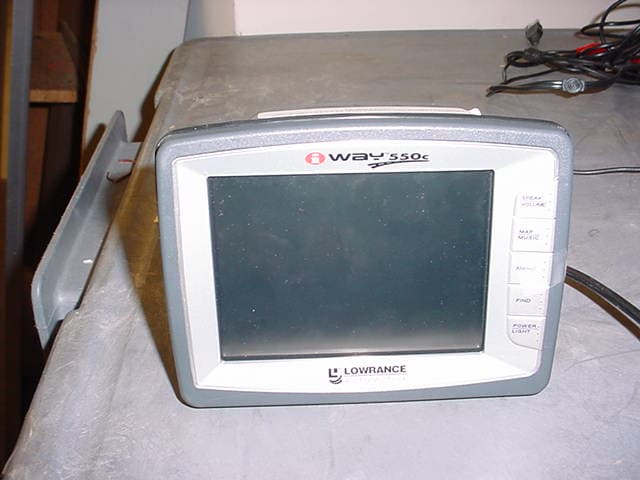
Jul 02, 2007GPS product with built in FM Transmitter
Equipment Class
DXX - Part 15 Low Power Communication Device TransmitterD6N6KXSYSTEM70
Sep 11, 1984HID - Part 15 TV Interface Device
Equipment Class
HID - Part 15 TV Interface Device