DBZHHEWIRELESS MICROPHONE TRANSMITTER
Lectrosonics Inc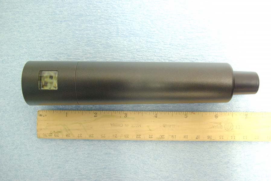
Click to zoom
Application Details
- Equipment Class
- TBF - Licensed Broadcast Transmitter Held to Face
- Date of Grant
- Dec 01, 2011
- Application Purpose
- Original Equipment
- Date of Application
- Dec 01, 2011
- Equipment Note
- WIRELESS MICROPHONE TRANSMITTER
- Frequency Range
- 470.10000000 - 537.50000000
- Company
- Lectrosonics Inc
- Country
- United States
Documents & Files
Document Text
Text extracted from the exhibit documents filed with the FCC. Open a document above to read the original.
Users Manual
HH Handheld Transmitter TECHNICAL DATA Rio Rancho, NM, USA www.lectrosonics.com • Digital Hybrid Wireless ® Technology • Standard thread-on capsules • Membrane switch and LCD interface • AA battery power • Selectable RF power at 50 and 100 mW • Talkback feature The HH Digital Hybrid Wireless handheld transmitter represents an elegant solution for a variety of wireless microphone applications including live performance, broadcast, AV rental and houses of worship. The HH incorporates many advanced features to provide high- quality speech and vocal reinforcement. Along with providing peerless audio quality with wide frequency response and dynamic range in native 400 Series mode, the technology used in the HH includes compatibility modes for Lectrosonics 200 Series, 100 Series and IFB receivers, and some systems from other top manufactur- ers. (Contact Lectrosonics for details.) Interchangeable Capsules Lectrosonics offers the HHC cardioid condenser capsule. Thread-on capsules from other manufacturers using a 1.25” opening and 28 thread pitch can also be used, including those from manufacturers such as EV, Shure ® , Heil Sound TM , Telefunken ® and others.* Digital Hybrid Wireless ® Digital Hybrid Wireless® is a revolutionary design that combines digital audio with an analog FM radio link to provide both outstanding audio quality and exemplary, noise-free RF performance. Us- ing a patented algorithm to encode 24-bit digital audio information in the transmitter into an analog format, the encoded signal is then transmitted over an analog FM wireless link. At the receiver, the signal is then decoded to restore the original digital audio. This process eliminates compandor artifacts and produces an audio frequency response flat to 20 kHz. (US Patent 7,225,135) * Shure and Telefunken are registered trademarks of their respective companies and have no association with Lectrosonics. Heil Sound is a trademark of Heil Sound Ltd. Preliminary 17 August 2011 581 Laser Road NE • Rio Rancho, NM 87124 USA • www.lectrosonics.com (505) 892-4501 • (800) 821-1121 • fax (505) 892-6243 • [email protected] Specifications Operating frequencies: † Block 470 470.100 - 495.600 Block 19 486.400 - 511.900 Block 20 512.000 - 537.500 Block 21 537.600 - 563.100 Block 22 563.200 - 588.700 Block 23 588.800 - 614.300 Block 606 606.000 - 631.500 Block 24 614.400 - 639.900 Block 25 640.000 - 665.500 Selectable RF Transmission Power The HH transmitter allows the user to select from among two power settings † depending on the needs of the situation. The lower RF power setting uses slightly less current, thus battery life is enhanced. The higher power setting provides greater range and resistance to drop- outs. Selecting the RF power is accomplished using the control menu. Mute and Talkback Functions The button on the back of transmitter below the head can be used to actuate an audio mute condition. This button can also be disabled using the control panel inside the battery compartment. An alternative function that can be actuated by this button is a talkback func- tion. In this state, the transmitter sends a signal to the Venue receiver when the button is pushed - the receiver then switches the audio to a second output which can be routed differently. This function can be used for talkback, cueing or other purposes depending on the application. This functionality requires a Venue receiver with firmware version X.XX or later. † Not available in all countries. Block 26 665.600 - 691.100 Block 27 691.200 - 716.700 Block 28 716.800 - 742.300 Block 29 742.400 - 767.900 Block 30 768.000 - 793.500 Block 779 779.120 - 809.750 Block 31 793.600 - 819.100 Block 32 819.200 - 844.700 Block 33 844.800 - 861.900 Frequency selection: 256 frequencies in 100 kHz steps (except block 23, 606, 33 and 779 - contact Lectrosonics for details) RF Power output: Selectable at 50 or 100 mW (25 or 50 mW for EU) Pilot tone: 25 to 32 kHz frequency (400 Series only); 5 kHz deviation (3 kHz for EU version) Frequency stability: ± 0.002% Deviation: ± 75 kHz (max) (±50 kHz for EU version) Spurious radiation: 90 dB below carrier Operating temperature range: -30° C to +60° C Input compressor: Dual envelope compressor, >30 dB range Gain control range: 44 dB; semi-log menu-driven control Modulation indicators: Dual bicolor LEDs indicate modulation of -20, -10, 0 and +10 dB referenced to full modulation, LCD bar-graph indicator Frequency response 40 Hz to 20 kHz (+/- 1dB) Low frequency roll-off: -3 dB @35, 50 and 70 Hz, 36 dB/octave, selectable Controls: External: Programmable mute/talkback button Battery compartment: Power, mute disable, menu/select, back and up/down arrow buttons for menu selection and settings. Battery: 2x AA with polarity protection and battery ejector Battery life: At 100mW: 5.5 hours (alkaline); 8-10 hours (lithium) (The HH transmits battery status to Lectrosonics 200 or 400 Series receivers.) Capsule Interface: 1.25” opening and 28 thread pitch Power available: 5V, 25 mA max Input impedance: 1000 Ohms Weight: 11.4 oz. with lithium batteries and HHC capsule Dimensions: 9.5” long x 1.97” diameter at largest point Emission Designator: XXXXXXXX* Specifications subject to change without notice. † Not all frequency blocks available in all countries. Consult your local representative or contact Lectrosonics for more information. Consumer Alert for US Users - FCC Order DA 10-92 Most users do not need a license to operate this wireless microphone system. Nevertheless, operating this microphone system without a license is subject to certain restrictions: the system may not cause harmful interference; it must operate at a low power level (not in excess of 50 milliwatts); and it has no protection from interference received from any other device. Purchasers should also be aware that the FCC is currently evaluating use of wireless microphone systems, and these rules are subject to change. For more information, call the FCC at 1-888- CALL-FCC (TTY: 1-888-T…
Text truncated - open the document above for the full version.
Cover Letter(s)
Page 1 of 2 December 2, 2011 Timco Engineering Inc. 849 NW State Road 45 Newberry, FL 32669 Applicant: Lectrosonics, Inc. 581 Laser Road Rio Rancho, NM 87124 Re: Confidentiality for submittal information regarding FCC ID number DBZHHE PRODUCT: Wireless Microphone operated under CFR47 part 74H Dear Sirs: Lectrosonics, Inc. requests that the material in the Schematics, Operational Description, Block diagram, and parts list be withheld from public disclosure pursuant to Sections 0.457 and 0.459 of the Commission’s Rules following grant of the application. In support of this request, Lectrosonics, Inc. submits the following information. CONFIDENTIAL FILES Exhibit File Parts List Conf PartList HHE.pdf Schematics Conf Schem HHE 1.pdf Schematics Conf Schem HHE 2.pdf Schematics Conf Schem HHE 3.pdf Block diagram Conf BlkDia HHE.pdf Operational Description Conf OpDes HHE 1.pdf Operational Description Conf OpDes HHE 2.pdf 1. Identification of the specific information for which confidential treatment is sought: The materials set forth in the Operational Description, block diagram, parts list, and Schematics, which are segregated, from the non-confidential exhibits of the application, are those for which confidentiality is sought. 2. Identification of the Commission proceeding in which the information was submitted or a description of the circumstances giving rise to the submission: The proceeding is that involving the application for equipment authorization (certification) under FCC ID No: DBZHHE ROGERS LABS, INC. 4405 West 259 th Terrace Louisburg, KS 66053 913 837-3214 Page 2 of 2 3. Explanation of the degree to which the information is commercial or financial, or contains a trade secret or is privileged: This material includes a detailed theory of operation, circuit diagrams, and schematic. As such, this material is treated as highly confidential business information. 4. Explanation of the degree to which the information concerns a service that is subject to competition: The material for which confidentiality is sought is employed in the design and manufacture of this transmitting equipment that is offered on a highly competitive basis. Customers for this equipment have a variety of competing sources. 5. Explanation of how disclosure of the information could result in substantial competitive harm: Disclosure would, in effect, give away the fruits of the labors of Lectrosonics, Inc.’s engineering personnel, who have designed the equipment and the manufacturing process. Disclosure would also offer competitors additional unwarranted insight into the state of the product development, thereby allowing competitors an advantage, not available to Lectrosonics, Inc. 6. Identification of any measures taken by the submitting party to prevent unauthorized disclosure: The information for which confidential treatment is sought is kept confidential by Lectrosonics, Inc. and not made available to third parties except pursuant to non-disclosure agreements. 7. Identification of whether the information is available to the public and the extent of any previous disclosure of the information to third parties: To the knowledge of those preparing this application, the information has not been disclosed publicly heretofore. While the general theory of operation of this equipment has been the subject of numerous disclosures in industry and standards groups as well as in rule making proceedings of the FCC, the protection sought is narrowly drawn and pertains to certain specific implementations of this radio technology. 8. Justification of the period during which the submitting party asserts that the material should not be available for public disclosure: This material should not be disclosed for at least 25 years. While improvements in design are made relatively frequently, disclosure of the design information would lead to insights into both design and manufacturing techniques that could have an adverse competitive effect for many years to come. As such, it is important that the design not be made available to unauthorized persons who might attempt to use knowledge of the design to compromise the applications for which the equipment will be employed. Should you require any further information, please contact the undersigned. Thank you for your consideration in this matter. Sincerely, Scot Rogers
Cover Letter(s)
April 11, 2008 Federal Communications Commission Equipment Approval Services Post Office Box 358315 Pittsburgh, Pennsylvania 15215-5315 To Whom It May Concern: Please be advised that Lectrosonics. Inc. has authorized Scot Rogers of Rogers Labs. Inc. to act on behalf in all matters relating to application for equipment authorization, including the signing of all documents relating to these matters and submittals. All acts carried out by Rogers Labs. Inc. on our behalf shall have the same effects as our own. Rogers Labs, Inc. is authorized to receive and exchange data between our company and the Commission. This Authorization is made pursuant to Paragraph 2.911 of FCC Rules CFR47. This Authorization is in effect until otherwise notified in writing. President Lectrosonics, Inc.
Cover Letter(s)
November 30, 2011 Timco Engineering Inc. 849 NW State Road 45 Newberry, FL 32669 Applicant: Lectrosonics, Inc. Equipment: FCC ID: DBZHHE 581 Laser Road CORES number: 0007-0674-81 Rio Rancho, NM 87124 FCC Rules: Part 74H, Wireless Microphone To Whom It May Concern: The form 731 and application have been electronically submitted and any attachments will be up loaded to your web site for use in obtaining a grant of certification. Confidentiality is requested as outlined below. Permanent Lectrosonics, Inc. requests that the material in the Parts List, Schematics, block diagram, and Operational Description be withheld from public disclosure in accordance with Section 0.459 of the Commission’s Rules, 47 C.F.R. 0.459, following grant of the application. A statement of confidentiality will be attached with the application at the time of submittal. Exhibit File Parts List Conf PartList HHE.pdf Schematics Conf Schem HHE 1.pdf Schematics Conf Schem HHE 2.pdf Schematics Conf Schem HHE 3.pdf Block diagram Conf BlkDia HHE.pdf Operational Description Conf OpDes HHE 1.pdf Operational Description Conf OpDes HHE 2.pdf Should you require any further information, please contact the undersigned. Thank you for your consideration in this matter. Sincerely, Scot Rogers Rogers Labs, Inc. Enclosures ROGERS LABS, INC. 4405 West 259 th Terrace Louisburg, KS 66053 Phone / Fax (913) 837-3214
External Photos
Rogers Labs, Inc. Lectrosonics, Inc. IC: 8024A-HHE 4405 W. 259th Terrace Model: HHE FCC ID: DBZHHE Louisburg, KS 66053 Test #: 111114A SN: 3, 4, 5 Phone/Fax: (913) 837-3214 Test to: FCC Parts 2 and 74, RSS-123 Issue 2 Date: November 27, 2011 Revision 1 File: ExtPho HHE Page 1 of 2 External Photographs of EUT Rogers Labs, Inc. Lectrosonics, Inc. IC: 8024A-HHE 4405 W. 259th Terrace Model: HHE FCC ID: DBZHHE Louisburg, KS 66053 Test #: 111114A SN: 3, 4, 5 Phone/Fax: (913) 837-3214 Test to: FCC Parts 2 and 74, RSS-123 Issue 2 Date: November 27, 2011 Revision 1 File: ExtPho HHE Page 2 of 2
ID Label/Location Info
Rogers Labs, Inc. Lectrosonics, Inc. IC: 8024A-HHE 4405 W. 259th Terrace Model: HHE FCC ID: DBZHHE Louisburg, KS 66053 Test #: 111114A SN: 3, 4, 5 Phone/Fax: (913) 837-3214 Test to: FCC Parts 2 and 74, RSS-123 Issue 2 Date: December 1, 2011 Revision 1 File: LabelSmpl HHE Page 1 of 1 Label Sample and placement
Internal Photos
Rogers Labs, Inc. Lectrosonics, Inc. IC: 8024A-HHE 4405 W. 259th Terrace Model: HHE FCC ID: DBZHHE Louisburg, KS 66053 Test #: 111114A SN: 3, 4, 5 Phone/Fax: (913) 837-3214 Test to: FCC Parts 2 and 74, RSS-123 Issue 2 Date: November 30, 2011 Revision 1 File: IntPho HHE Page 1 of 3 Internal Photographs of EUT Rogers Labs, Inc. Lectrosonics, Inc. IC: 8024A-HHE 4405 W. 259th Terrace Model: HHE FCC ID: DBZHHE Louisburg, KS 66053 Test #: 111114A SN: 3, 4, 5 Phone/Fax: (913) 837-3214 Test to: FCC Parts 2 and 74, RSS-123 Issue 2 Date: November 30, 2011 Revision 1 File: IntPho HHE Page 2 of 3 ID Label Placement Rogers Labs, Inc. Lectrosonics, Inc. IC: 8024A-HHE 4405 W. 259th Terrace Model: HHE FCC ID: DBZHHE Louisburg, KS 66053 Test #: 111114A SN: 3, 4, 5 Phone/Fax: (913) 837-3214 Test to: FCC Parts 2 and 74, RSS-123 Issue 2 Date: November 30, 2011 Revision 1 File: IntPho HHE Page 3 of 3
Parts List/Tune Up Info
Lectrosonics Standard Test & Alignment Procedure Part number(s): HH Hardware version(s): 17424B (audio) & 17423B (radio) Firmware version(s): 0.93 Part number(s): HHAU Hardware version(s): 17424B (audio) & 17423B (radio) Firmware version(s): ? Part number(s): HH/E01 Hardware version(s): 17424B (audio) & 17423B (radio) Firmware version(s): ? Part number(s): HH/E02 Hardware version(s): 17424B (audio) & 17423B (radio) Firmware version(s): ? Common name: hand held transmitter Author(s): Rodney Wildhagen & Cruz Garcia Test procedure version: 01.00 Date: 04 Oct 2011 Initial setup: Audio Board only Audio board with PIC18F67J11 μC IC Step Measurement name& description Measurement result (Typ) Test Segment 10 of 60 Program μC IC and Current draw Audio board only CAUTION When reprograming already tested devices, be sure to set device programmer GUI to pr eserve all settings (block, limiter settings, etc.). In Microchip MPLAB this is done by selecting Program mer > Settings > Program > Preserve EEPROM on program > Apply > OK. Failure to do so will resu lt in loss of all assigned variable values such as frequency block, limiter setti ng, indicator settings, etc. Note This need only be performed at the factory the first time the DUT is powered up, when μC IC is replaced, or when a firmware update is desired and confirmed to be appropriate. Apply +3.0VDC, 300mA current limit in at battery contact J8 (J9 is circuit common) Note In order to program DUT, JU1 must be jumpered or the power button must be pressed during the entire programming process. Remove JU1 jumper after programming. Program μC IC with programmi ng cable connected at J6 (ICSP port) Remove ICSP cable Measure current draw 50 to 500 mA (117) Note The goal here is only to ensure the audio board powers up and is not burning up with fever Remove DC voltage from Battery contacts a nd apply firmware versi on label to audio board Test Segment 20 of 60 NOTE: This segment may be performed using one audio board to test multiple radio boards Initial setup: Known good, pre-tested audi o board with PIC18F67J11 μC IC running firmware versi on appropriate & current for part number connected to an untested radio board Test panel key pad or appropr iate test rig connected to audio board J2 Apply +3.0VDC, 300mA current li mit in at battery contact J8 (J9 is circuit common). All voltage measurements refe renced to circuit common All demodulated carrier and carrier deviation measurements taken with a Hewlett Packard 8901B modulation analyzer with no 8901B filters selected. Use of other instruments may yield di fferent results particularly measurements pertaining to noise and phase and measurements where noise is a significant factor All audio stimulus signals a pplied to audio input rig defined at foot of this document All audio stimulus signals are single ended. Carrier power for various part numbers are as follows: HH=100mW, HHAU & HH/E01= 50mW and HH/E02 All audio measurements taken with a ≤ 10 Hz HPF and 80KHz LPF (use filter on audio signal analyzer, no modulation analyzer unle ss otherwise specified). This font indicates use of the A lternate Method to manual testing. The Alternate Method uses the LectroLink apparatus and either the LecNet2 Command Terminal Utility or the O:\ATE\MTE\HH\ H H_LectroLink_Control.exe program. Test steps bearing the same number indicates alternate method(s). Step Measurement name & description Measurement result (Typ) Power Up sequence and current draw Prerequisite(s): FPGA IC programmed Hold test power button on test panel key pad for 3 seconds until DUT powers up Observe behavior of test key pa d LED -10 LED turns on red, then -20 LED turns on red then both off. both LED's flash red once then green once Observe behavior of te st audio board LCD "HH" "Vx.xx" "block XX" "Hybrid" ? ? ? ? frequency "Main" screen Note a flashing antenna icon inside a indicates the PLL is not locked Measure current draw 50 to 500 mA (145) Note The goal here is only to ensure the DU T powers up and is not burning up with fever Audio board frequency block assignment Prerequisite(s): FPGA IC programmed Note: This part has to be performed only on the fi rst DUT to setup Test A udio Board for the Block. Momentarily connect audio board TP5 to TP22 (enter Set-up mode) Note Entering Set-up mode is not necessary if the Alternate Method is exercised. Using the test key pad navigate to the "Block" screen. Press UP or DWN button on the test pane l key pad to change unit to desired Block block= (set freq block 470,19-33, 944 standard 400-999 extended) Turn DUT Off then back On and check to see if the Block set. VCO adjustment & VCO start-up test Prerequisite(s): FPGA IC programmed Using the test key pad na vigate to the "Freq." screen Press MENU/SEL and UP button simultaneously to change frequency to highest fr equency. (pressing MUNU/SEL and UP simultaneously will step the frequency up in incr ements of 16 only pressing the UP or DOWN buttons will only increment by 1) channel=XX set channel (0(00) to 1020 (ff) in normal tuning mode, 80 is 512) Adjust radio board C1 for 2.5 VDC at radio board TP1 (VCO_CONT) +2.45 to +2.55 VDC (+2.5) No DC power in at battery contacts Wait until transmitter completely powers down (approx. 4 sec) Apply +3.0VDC, 500mA current limit in at ba ttery contact J8 (J9 is circuit common) Hold Power button for 3 seconds (make sure unit come on). Measure carrier signal power to be sure the VCO starts on power up at selected carrier frequency ≥ +10 dBm Using the test key pad na vigate to the "Freq." screen Press MENU/SEL and UP button simultaneously to cha nge frequency to lowest fr equency. (pressing MUNU/SEL and UP simultaneously will step the frequency up in incr ements of 16 only pressing the UP or DOWN buttons will only increment by 1) channel=XX set channel (0(00) to 1020 (ff) in normal tuning mode, 80 is 512) Measure DC voltage at radio board TP1 (VCO_CONT) +0.6 to +1.2 VDC No DC power in at battery conta…
Text truncated - open the document above for the full version.
RF Exposure Info
Rogers Labs, Inc. Lectrosonics, Inc. IC: 8024A-HHE 4405 W. 259th Terrace Model: HHE FCC ID: DBZHHE Louisburg, KS 66053 Test #: 111114A SN: 3, 4, 5 Phone/Fax: (913) 837-3214 Test to: FCC Parts 2 and 74, RSS-123 Issue 2 Date: November 27, 2011 Revision 1 File: RFExp HHE Page 1 of 1
Test Report
NVLAP Lab Code: 200087-0 Rogers Labs, Inc. Lectrosonics, Inc. IC: 8024A-HHE 4405 West 259 TH Terrace Model: HHE FCC ID: DBZHHE Louisburg, KS 66053 Test #: 111114A SN: 3, 4, 5 Phone/Fax: (913) 837-3214 Test to: FCC Parts 2 & 74H, RSS-123, Issue 2 Date: November 27, 2011 Revision 1 File: Lectrosonics HHE TstRpt 111114A Page 1 of 31 Application Submittal Test Report Industry Canada and FCC Grant of Certification Model: HHE Wireless Microphone Transmitter FCC ID: DBZHHE IC: 8024A-HHE Frequency Range: 470.1 - 537.5 MHz Operating under rule of RSS-123, Issue 2 and CFR47 Part 74, Subpart H FOR LECTROSONICS, INC. 581 Laser Road Rio Rancho, NM 87124 Test Report Number: 111114A Authorized Signatory Scot D. Rogers NVLAP Lab Code: 200087-0 Rogers Labs, Inc. Lectrosonics, Inc. IC: 8024A-HHE 4405 West 259 TH Terrace Model: HHE FCC ID: DBZHHE Louisburg, KS 66053 Test #: 111114A SN: 3, 4, 5 Phone/Fax: (913) 837-3214 Test to: FCC Parts 2 & 74H, RSS-123, Issue 2 Date: November 27, 2011 Revision 1 File: Lectrosonics HHE TstRpt 111114A Page 2 of 31 Engineering Test Report For Application of Certification For Industry Canada and FCC Lectrosonics, Inc. 581 Laser Road Rio Rancho, NM 87124 Larry Fisher President Model: HHE Wireless Microphone Transmitter Frequency: 470.1 - 537.5 MHz FCC ID: DBZHHE IC: 8024A-HHE Test Date: November 14, 2011 Certifying Engineer Scot D. Rogers Rogers Labs, Inc. 4405 West 259TH Terrace Louisburg, KS 66053 Telephone/ Facsimile (913) 837-3214 This report shall not be reproduced except in full, without the written approval of the laboratory. This report must not be used by the client to claim product endorsement by NVLAP, NIST, or any agency of the U.S. Government. ROGERS LABS, INC. 4405 West 259th Terrace Louisburg, KS 66053 Phone / Fax (913) 837-3214 NVLAP Lab Code: 200087-0 Rogers Labs, Inc. Lectrosonics, Inc. IC: 8024A-HHE 4405 West 259 TH Terrace Model: HHE FCC ID: DBZHHE Louisburg, KS 66053 Test #: 111114A SN: 3, 4, 5 Phone/Fax: (913) 837-3214 Test to: FCC Parts 2 & 74H, RSS-123, Issue 2 Date: November 27, 2011 Revision 1 File: Lectrosonics HHE TstRpt 111114A Page 3 of 31 Table of contents TABLE OF CONTENTS .................................................................................................... 3 FORWARD ....................................................................................................................... 5 OPINION / INTERPRETATION OF RESULTS ................................................................. 5 APPLICABLE STANDARDS & TEST PROCEDURES .................................................... 5 ENVIRONMENTAL CONDITIONS.................................................................................... 5 APPLICATION FOR CERTIFICATION ............................................................................. 6 EQUIPMENT TESTED ...................................................................................................... 7 EQUIPMENT FUNCTION AND SYSTEM DESCRIPTION ................................................ 8 EQUIPMENT AND CABLE CONFIGURATIONS ............................................................. 8 Antenna Port Conducted Emission Test Procedure .............................................................................................. 8 Radiated Emission Test Procedure ......................................................................................................................... 8 UNITS OF MEASUREMENTS .......................................................................................... 8 TEST SITE LOCATIONS .................................................................................................. 9 LIST OF TEST EQUIPMENT ............................................................................................ 9 RADIO FREQUENCY POWER OUTPUT ......................................................................... 10 Measurements Required .......................................................................................................................................... 10 Radio Frequency Power Output Test Arrangement .............................................................................................. 10 Figure One Power Output ...................................................................................................................................... 11 Radio Frequency Power Output Results ................................................................................................................ 11 MODULATION CHARACTERISTICS ............................................................................... 12 Modulation Characteristics Measurements Required ........................................................................................... 12 Test Arrangement ..................................................................................................................................................... 12 Modulation Characteristic Results .......................................................................................................................... 12 Figure Two Audio Frequency Response Characteristics ....................................................................................... 13 Figure Three Deviation Characteristics .................................................................................................................. 13 Figure Four Frequency Response of Audio low Pass Filter ................................................................................... 14 OCCUPIED BANDWIDTH ................................................................................................ 14 NVLAP Lab Code: 200087-0 Rogers Labs, Inc. Lectrosonics, Inc. IC: 8024A-HHE 4405 West 259 TH Terrace Model: HHE FCC ID: DBZHHE Louisburg, KS 66053 Test #: 111114A SN: 3, 4, 5 Phone/Fax: (913) 837-3214 Test to: FCC Parts 2 & 74H, RSS-123, Issue 2 Date: November 27, 2011 Revision 1 File: Lectrosonics HHE TstRpt 111114A Page 4 of 31 Occupied Bandwidth…
Text truncated - open the document above for the full version.
Test Setup Photos
Rogers Labs, Inc. Lectrosonics, Inc. IC: 8024A-HHE 4405 W. 259th Terrace Model: HHE FCC ID: DBZHHE Louisburg, KS 66053 Test #: 111114A SN: 3, 4, 5 Phone/Fax: (913) 837-3214 Test to: FCC Parts 2 and 74, RSS-123 Issue 2 Date: November 27, 2011 Revision 1 File: TSup HHE Page 1 of 1 Photographs of Test Setup
Contact Information
Applicant
Robert Cunnings(Vice President, Engineering)
Test Firm
Rogers Labs, Inc.Scot Rogers
Technical Specifications
| # | Rule Parts | Frequency Range | Power Output | Emission | Tolerance |
|---|---|---|---|---|---|
| 1 | 74.861 | 470.1 MHz - 537.5 MHz | 100.00 mW | 180KF3E | 0.0020000000 % |
Other Applications from Lectrosonics Inc
DBZT20A
Jun 05, 2026Digital Hybrid Wireless microphone transmitter
Equipment Class
TLD - Licensed LPAS DeviceDBZT20B
Jun 05, 2026Digital Hybrid Wireless microphone transmitter
Equipment Class
TLD - Licensed LPAS DeviceDBZDCHTB
Sep 08, 2024Digital Camera Hop Transmitter
Equipment Class
DWM - Part 15 Wireless Microphone
DBZDBSMA
Jan 25, 2021Digital Wireless Microphone Transmitter
Equipment Class
TLD - Licensed LPAS Device
DBZSMWB79
Jul 20, 2020Body-worn Wireless Microphone Transmitters
Equipment Class
TLD - Licensed LPAS Device