DBZMM400Wireless Microphone Transmitter
Lectrosonics Inc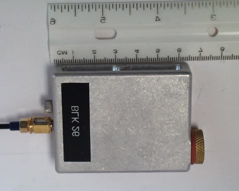
Click to zoom
Application Details
- Equipment Class
- TBC - Licensed Broadcast Station Transmitter
- Date of Grant
- Jun 04, 2002
- Application Purpose
- Original Equipment
- Date of Application
- Jun 04, 2002
- Equipment Note
- Wireless Microphone Transmitter
- Frequency Range
- 614.00000000 - 806.00000000
- Company
- Lectrosonics Inc
- Country
- United States
Documents & Files
Document Text
Text extracted from the exhibit documents filed with the FCC. Open a document above to read the original.
Users Manual
MM200/MM400 FREQUENCY-AGILE UHF MINIATURE BELT-PACK TRANSMITTER LECTROSONICS, INC. Rio Rancho, NM www.lectrosonics.com OPERATING INSTRUCTIONS and trouble-shooting guide 2 The MM400 transmitter is FCC type accepted under Part 74: 536-608 MHz and 614-806 MHz WARNING! TO PREVENT INTERNAL CORROSION! If the transmitter is wet (either due to immersion or high levels of perspiration), BEFORE opening any covers or connectors, carefully blot the transmitter dry with a clean paper towel or cloth. Remove all moisture. After opening any connector or cover, carefully blot up any remaining moisture that may have remained around the seal. THIS IS IMPORTANT! DO NOT CLOSE ANY COVER OR CONNECTOR BEFORE MAKING CERTAIN THERE IS NO MOISTURE IN OR NEAR THE OPENING. After use, it is important to store the transmitter in a dry place with all access doors and connectors opened to allow any internal humidity to evaporate. Specifically, open the battery door, the frequency cover plate and fully unscrew and remove the microphone connector before storing. Do NOT store wet and do NOT store sealed. If moisture is sealed inside the unit it has nowhere to go other than to chemically react with and destroy components and the printed circuit board. TABLE OF CONTENTS WARNING! TO PREVENT INTERNAL CORROSION!................................ 2 INTRODUCTION................................................................................................... 3 GENERAL TECHNICAL DESCRIPTION .............................................................. 3 Temporary Placeholder ......................................................................................... 4 CONTROLS AND FUNCTIONS ............................................................................ 6 BATTERY INSTALLATION .................................................................................... 7 OPERATING INSTRUCTIONS .............................................................................. 8 OPERATING NOTES ............................................................................................ 8 ADJUSTING THE TRANSMITTER FREQUENCY............................................... 8 MICROPHONE RF Bypassing............................................................................. 9 TROUBLESHOOTING ........................................................................................... 9 SPECIFICATIONS AND FEATURES................................................................. 10 SERVICE AND REPAIR...................................................................................... 11 RETURNING UNITS FOR REPAIR .................................................................... 12 WARRANTY..........................................................................................Back cover 3 Frequency Agile UHF Miniature Belt-Pack Transmitter Rio Rancho, NM – USA INTRODUCTION Thank you for selecting the Lectrosonics MM400 frequency agile UHF miniature transmitter. The MM400 combines over 80 years of engineering experience with the very latest components, in a design that addresses the most demanding professional applications. The design of the MM400 was the direct result of numerous conversations with users, staging and touring companies and dealers across the US. The specific concerns and needs brought up in these conversations led directly to the development of the operational features offered on the MM400. Two hundred fifty six frequencies are user selectable in 100kHz steps to alleviate interference problems in traveling venues. The MM400 is a rugged, machined stainless steel package with a removable, spring loaded belt clip. 3.3 Volts of bias voltage is available to power electret mics. Level indicating LEDs are provided on the control panel to make level settings quick and accurate, without having to view the receiver. The battery compartment accepts AA alkaline or lithium batteries. The antenna is a detachable, locking ¼ wavelength flexible bronze cable that connects to a 50 Ohm SMA port on the transmitter. Only the MM400 transmitter is covered in this manual. Companion receivers are covered in separate manuals. The transmitter will operate with any 400 Series Lectrosonics receiver in the same frequency group. If you have a miniature transmitter marked as a MM200 transmitter, this is a factory programmed variant of the MM400 that uses the Digital Signal Processor in the MM400 to model the dual band compander used in the 200 series with the appropriate compander time constants and frequency division. Since the signals are converted from analog to digital, processed and then converted back to analog, there is a delay as with all digital audio systems. This delay is 1.6 mS or an equivalent audio path length delay of 18 inches. With the exception of the audio processing, all other comments and instructions in this manual can be applied to either the MM400 or MM200. GENERAL TECHNICAL DESCRIPTION If the unit will be used in a wet environment (possible immersion, perspiration, rain scenes, etc.) – be certain all connectors have intact gaskets and that a properly sealed Lectrosonics’ waterproof mic connector is installed and used with the microphone. GENERAL The 400 system uses 75kHz wide deviation for an extremely high signal to noise ratio. The switching power supplies provide constant voltages to the transmitter circuits from the beginning (1.5 Volts) to the end (0.85 Volts) of battery life. The input amplifier uses an ultra low noise op amp for quiet operation. It is gain controlled with a wide range dual envelope input compressor which cleanly limits input signal peaks over 30dB above full modulation. 4 MM400 Block Diagram DIGITAL HYBRID TECHNOLOGY All wireless links suffer from channel noise to some degree, and all wireless microphone systems seek to minimize the impact of that noise on the desired signal. Conventional analog systems use compandors for enhanced dynamic range, at the cost of subtle artifacts (known as “pumping” and “breath…
Text truncated - open the document above for the full version.
Cover Letter(s)
May 13, 2002 Timco Engineering Inc. 849 NW State Road 45 Newberry, FL 32669 Office of Engineering and Technology Federal Communications Commission Columbia, MD 21046 Applicant: Lectrosonics, Inc. 581 Laser Road Rio Rancho, NM 87124 Re: Confidentiality for submittal information regarding FCC ID number DBZ-MM400 PRODUCT: Wireless Microphone transmitter operating under part 74. Dear Sirs: Lectrosonics, Inc. requests that the material in the Block diagram, Schematics, and Operational Description be withheld from public disclosure in accordance with Section 0.459 of the Commissions Rules, 47 C.F.R. 0.459 (1998), following grant of the application. In support of this request, Lectrosonics, Inc. submits the following: 1. Identification of the specific information for which confidential treatment is sought: The materials set fourth in the Operational Description, Block Diagram, and Schematics, which are segregated from the non-confidential exhibits of the application, are those for which confidentiality is sought. 2. Identification of the Commission proceeding in which the information was submitted or a description of the circumstances giving rise to the submission: The proceeding is that involving the application for equipment authorization (certification) under FCC ID No: DBZ-MM400 3. Explanation of the degree to which the information is commercial or financial, or contains a trade secret or is privileged: This material includes a detailed theory of operation and circuit diagrams, (schematic diagrams). As such, this material is treated as highly confidential business information. ROGERS LABS, INC. 4405 West 259 th Terrace Louisburg, KS 66053 4. Explanation of the degree to which the information concerns a service that is subject to competition: The material for which confidentiality is sought is employed in the design and manufacture of this transmitting equipment that is offered on a highly competitive basis. Customers for this equipment have a variety of competing sources. 5. Explanation of how disclosure of the information could result in substantial competitive harm: Disclosure would, in effect, give away the fruits of the labors of Lectrosonics, Inc.’s engineering personnel, who have designed the equipment and the manufacturing process. Disclosure would also offer competitors additional unwarranted insight into the state of the product development, thereby allowing competitors an advantage, not available to Lectrosonics, Inc. 6. Identification of any measures taken by the submitting party to prevent unauthorized disclosure: The information for which confidential treatment is sought is kept confidential by Lectrosonics, Inc. and not made available to third parties except pursuant to non-disclosure agreements. 7. Identification of whether the information is available to the public and the extent of any previous disclosure of the information to third parties: To the knowledge of those preparing this application, the information has not been disclosed publicly heretofore. While the general theory of operation of this equipment has been the subject of numerous disclosures in industry and standards groups as well as in rule making proceedings of the FCC, the protection sought is narrowly drawn and pertains to certain specific implementations of this radio technology. 8. Justification of the period during which the submitting party asserts that the material should not be available for public disclosure: This material should not be disclosed for at least 25 years. While improvements in design are made relatively frequently, disclosure of the design information would lead to insights into both design and manufacturing techniques that could have an adverse competitive effect for many years to come. This equipment is designed for commercial, industrial, and governmental applications. As such, unlike most consumer equipment, this equipment will be used for more than a decade in some cases. As such, it is important that the design not be made available to unauthorized persons who might attempt to use knowledge of the design to compromise the applications for which the equipment will be employed. 9. Any other information that the party seeking confidential treatment believes may be useful in assessing whether its request for confidentiality should be granted: See item 8 above. Note that the equipment for which approval is being sought will be employed in applications that inherently place a premium on security. Should you require any further information, please contact the undersigned. Thank you for your consideration in this matter. Sincerely, Scot Rogers
External Photos
ROGERS LABS, INC. Lectrosnics, Inc. 4405 W. 259th Terrace MODEL: MM200/MM400 Louisburg, KS 66053 Test #: 020410 FCC ID: DBZ MM400 Phone/Fax: (913) 837-3214 Test to: FCC Parts 2 and 74 Page 1 of 2 MM400ExtPho.doc 5/1/2002 External Photos of for MM200 ROGERS LABS, INC. Lectrosnics, Inc. 4405 W. 259th Terrace MODEL: MM200/MM400 Louisburg, KS 66053 Test #: 020410 FCC ID: DBZ MM400 Phone/Fax: (913) 837-3214 Test to: FCC Parts 2 and 74 Page 2 of 2 MM400ExtPho.doc 5/1/2002
ID Label/Location Info
ROGERS LABS, INC. Lectrosnics, Inc. 4405 W. 259th Terrace MODEL: MM200/MM400 Louisburg, KS 66053 Test #: 020410 FCC ID: DBZ MM400 Phone/Fax: (913) 837-3214 Test to: FCC Parts 2 and 74 Page 1 of 1 MM400IdLbl.doc 5/1/2002 FCC ID Label Location and information for MM400
Internal Photos
ROGERS LABS, INC. Lectrosnics, Inc. 4405 W. 259th Terrace MODEL: MM200/MM400 Louisburg, KS 66053 Test #: 020410 FCC ID: DBZ MM400 Phone/Fax: (913) 837-3214 Test to: FCC Parts 2 and 74 Page 1 of 3 MM400Tsup.doc 4/9/2002 Internal Photographs for MM400 ROGERS LABS, INC. Lectrosnics, Inc. 4405 W. 259th Terrace MODEL: MM200/MM400 Louisburg, KS 66053 Test #: 020410 FCC ID: DBZ MM400 Phone/Fax: (913) 837-3214 Test to: FCC Parts 2 and 74 Page 2 of 3 MM400Tsup.doc 4/9/2002 ROGERS LABS, INC. Lectrosnics, Inc. 4405 W. 259th Terrace MODEL: MM200/MM400 Louisburg, KS 66053 Test #: 020410 FCC ID: DBZ MM400 Phone/Fax: (913) 837-3214 Test to: FCC Parts 2 and 74 Page 3 of 3 MM400Tsup.doc 4/9/2002
Test Report
TEST REPORT For APPLICATION of CERTIFICATION for LECTROSONICS, INC. 581 Laser Road Rio Rancho, NM 878124 Larry Fisher Vice President of Engineering MODEL: MM400 and MM200E NAME: Wireless Microphone Transmitter FREQUENCY: 536 – 806 MHz FCC ID: DBZ MM400 Test Date: April 16, 2002 Certifying Engineer: Scot D. Rogers ROGERS LABS, INC. 4405 West 259 TH Terrace Louisburg, KS 66053 PHONE: (913) 837-3214 FAX: (913) 837-3214 This report shall not be reproduced except in full, without the written approval of the laboratory. This report must not be used by the client to claim product endorsement by NVLAP or any agency of the U.S. Government. ROGERS LABS, INC. 4405 West 259 th Terrace Louisburg, KS 66053 Phone / Fax (913) 837-3214 NVLAP Accredited Laboratory NVLAP Lab Code: 200087-0 ROGERS LABS, INC. Lectrosonics, Inc. 4405 West 259 TH Terrace MODEL: MM400 and MM200E Louisburg, KS 66053 Test #: 020410 FCC ID DBZ MM400 Phone/Fax: (913) 837-3214 Test to: FCC Parts 2 & 74 Page 2 of 24 MM400Testrpt.DOC 05/24/2002 TABLE OF CONTENTS FORWARD: 3 APPLICABLE STANDARDS & TEST PROCEDURES 3 LIST OF TEST EQUIPMENT 3 2.1033(C) APPLICATION FOR CERTIFICATION: 4 2.1046 RF POWER OUTPUT 6 Measurements Required: 6 Test Arrangement: 6 Results: 7 2.1047 MODULATION CHARACTERISTICS 9 Measurements Required: 9 Test Arrangement: 9 Results: 9 2.1049 OCCUPIED BANDWIDTH 11 Measurements Required: 11 Test Arrangement: 11 Results: 13 2.1051 SPURIOUS EMISSIONS AT ANTENNA TERMINALS 13 Measurements Required: 13 Test Arrangement: 13 Results: 15 2.1053 FIELD STRENGTH OF SPURIOUS RADIATION 15 Measurements Required: 15 Test Arrangement: 15 Results : 17 2.1055 FREQUENCY STABILITY 18 Measurements Required: 18 Test Arrangement: 19 Results: 20 APPENDIX 21 NVLAP Accredited Laboratory NVLAP Lab Code: 200087-0 ROGERS LABS, INC. Lectrosonics, Inc. 4405 West 259 TH Terrace MODEL: MM400 and MM200E Louisburg, KS 66053 Test #: 020410 FCC ID DBZ MM400 Phone/Fax: (913) 837-3214 Test to: FCC Parts 2 & 74 Page 3 of 24 MM400Testrpt.DOC 05/24/2002 FORWARD: In accordance with the Federal Communications Code of Federal Regulations, dated October 1, 2001, Part 2 Subpart J, Paragraphs 2.907, 2.911, 2.925, 2.926, 2.1031 through 2.1057 and; Part 74 Subpart H; Paragraphs 74.801 through 74.861 the following is submitted: Applicable Standards & Test Procedures a) In accordance with the Federal Communications Code of Federal Regulations, dated October 1, 2001, Part 2, Subpart J, Paragraphs 2.907, 2.911, 2.913, 2.925, 2.926, 2.1031 through 2.1057, and applicable paragraphs of Part 74 the following is submitted. b) Test procedures used are the established Methods of Measurement of Radio-Noise Emissions as described in the ANSI 63.4-1992 and ANSI/TIA/EIA 603. List of Test Equipment A Hewlett Packard 8591EM and or 8562A Spectrum Analyzer was used as the measuring device for the emissions testing. The analyzer settings used are described in the following table. Refer to the Appendix for a complete list of Test Equipment. NVLAP Accredited Laboratory NVLAP Lab Code: 200087-0 ROGERS LABS, INC. Lectrosonics, Inc. 4405 West 259 TH Terrace MODEL: MM400 and MM200E Louisburg, KS 66053 Test #: 020410 FCC ID DBZ MM400 Phone/Fax: (913) 837-3214 Test to: FCC Parts 2 & 74 Page 4 of 24 MM400Testrpt.DOC 05/24/2002 HP 8591EM SPECTRUM ANALYZER SETTINGS CONDUCTED EMISSIONS: RBW AVG. BW DETECTOR FUNCTION 9 kHz 30 kHz Peak/Quasi Peak RADIATED EMISSIONS (30 – 1000 MHz): RBW AVG. BW DETECTOR FUNCTION 120 kHz 300 kHz Peak/Quasi Peak HP 8562A SPECTRUM ANALYZER SETTINGS RADIATED EMISSIONS (1 – 40 GHz): RBW AVG. BW DETECTOR FUNCTION 1 MHz 1 MHz Peak/Average ANTENNA CONDUCTED EMISSIONS: RBW AVG. BW DETECTOR FUNCTION 100 kHz 300 kHz Peak 2.1033(C) Application for Certification: (1) The full name and mailing address of the manufacturer of the device and the applicant for certification. Lectrosonics, Inc. 581 Laser Road Rio Rancho, NM 87124 (2) FCC identifier. DBZ MM400 (3) A copy of the installation and operating instructions to be furnished the user. Refer to the instruction manual furnished with this application for details. (4) Type or types of emission. 180KF3E (5) Frequency range. 536 to 806 MHz with lockout provisions on restricted frequency bands between 608 and 614 MHz. (6) Range of operating power values or specific operating power levels, and description of any means provided for variation of operating power. The output power is factory set to 100 mW NVLAP Accredited Laboratory NVLAP Lab Code: 200087-0 ROGERS LABS, INC. Lectrosonics, Inc. 4405 West 259 TH Terrace MODEL: MM400 and MM200E Louisburg, KS 66053 Test #: 020410 FCC ID DBZ MM400 Phone/Fax: (913) 837-3214 Test to: FCC Parts 2 & 74 Page 5 of 24 MM400Testrpt.DOC 05/24/2002 (nominal). The EUT has no provision for operator variation of the output power. (7) Maximum power rating as defined in the applicable part(s) of the rules. As stated in CFR 47, 74.861(e)(ii), the maximum permissible output power allowed is 250 mW. (8) The dc voltages applied to and dc currents into the several elements of the final radio frequency amplifying device for normal operation over the power range. The EUT final amplification stage runs at 3.3 volts with 53 mA current for a power requirement of 175 mW. (9) Tune-up procedure over the power range, or at specific operating power levels. Refer to the tune-up procedure furnished with this application for details. (10) A schematic diagram and a description of all circuitry and devices provided for determining and stabilizing frequency, for suppression of spurious radiation, for limiting modulation, and for limiting power. Refer to the schematics furnished with this application for details. (11) A photograph or drawing of the equipment identification plate or label shows the information to be placed thereon. Refer to the FCC identification label information furnished with this application for details. (12) Photographs (8'' x 10'') of the equipment of sufficient clarity to reveal equipment construction and layout, …
Text truncated - open the document above for the full version.
Contact Information
Applicant
Robert Cunnings(Vice President, Engineering)
Test Firm
Rogers Labs, Inc.Scot Rogers
Technical Specifications
| # | Rule Parts | Frequency Range | Power Output | Emission | Tolerance |
|---|---|---|---|---|---|
| 2 | 74 | 614 MHz - 806 MHz | 100.00 mW | 180KF3E | 2.7 ppm |
Other Applications from Lectrosonics Inc
DBZT20A
Jun 05, 2026Digital Hybrid Wireless microphone transmitter
Equipment Class
TLD - Licensed LPAS DeviceDBZT20B
Jun 05, 2026Digital Hybrid Wireless microphone transmitter
Equipment Class
TLD - Licensed LPAS DeviceDBZDCHTB
Sep 08, 2024Digital Camera Hop Transmitter
Equipment Class
DWM - Part 15 Wireless Microphone
DBZDBSMA
Jan 25, 2021Digital Wireless Microphone Transmitter
Equipment Class
TLD - Licensed LPAS Device
DBZSMWB79
Jul 20, 2020Body-worn Wireless Microphone Transmitters
Equipment Class
TLD - Licensed LPAS Device