DBZSMQHBody worn wireless microphone transmitter
Lectrosonics Inc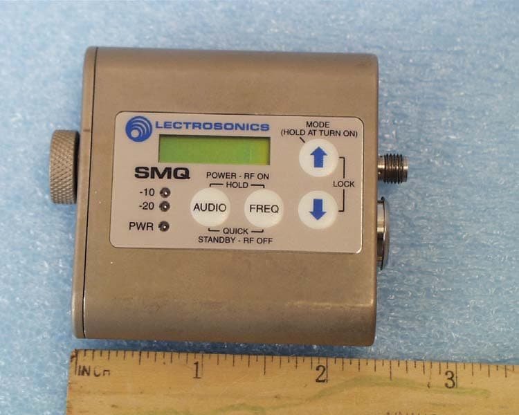
Click to zoom
Application Details
- Equipment Class
- TBT - Licensed Broadcast Transmitter Worn on Body
- Date of Grant
- Nov 06, 2006
- Application Purpose
- Original Equipment
- Date of Application
- Aug 27, 2006
- Equipment Note
- Body worn wireless microphone transmitter
- Frequency Range
- 691.20000000 - 767.90000000
- Company
- Lectrosonics Inc
- Country
- United States
Documents & Files
Document Text
Text extracted from the exhibit documents filed with the FCC. Open a document above to read the original.
Users Manual
SM Super Miniature Belt-Pack Transmitter Including SMD, SMQ With Digital Hybrid Wireless™ Technology INSTRUCTION MANUAL Rio Rancho, NM, USA www.lectrosonics.com Fill in for your records: Serial Number: Purchase Date: SM LECTROSONICS, INC.2 Thank you for selecting the Lectrosonics SM ultra- miniature transmitter. The unique design provides several distinct features for professional applications: Outstanding RF operating range Superb audio quality Ultra-lightweight, corrosion resistant housing Water resistant seals for use in damp environments Programmable compatibility modes for maximum versatility The Digital Hybrid Wireless TM design (US Patent Pending) combines 24-bit digital audio with analog FM resulting in a system that has the same operating range as analog systems (plus the graceful failure at the limits of that range), the same spectral efficiency as analog systems, the same long battery life as analog systems, but with the excellent audio found in digital systems. The SM uses a standard Lectrosonics 5-pin type input jack for use with electret lavaliere mic, dynamic mic, or line level signals. A water resistant control panel with LCD, membrane switches and multi-color LEDs make input gain adjustments and frequency and compatibility mode selection quick and accurate, without having to view the receiver. The battery compartment accepts an AA lithium battery. Plus, the SM is machined from a solid aluminum block to provide an extremely light- weight and rugged package. A special non-corrosive finish (the same one used by NASA) resists salt water exposure and perspiration in extreme environments. The DSP-based design works with all Digital Hybrid recievers, and is backward compatible with Lectrosonics 200 and 100 Series and IFB receivers and some other brands of analog wireless receivers. Only the SM transmitter is covered in this manual. Compan- ion receivers are covered in separate manuals. Super-Minature Belt Pack Transmitter Rio Rancho, NM3 Table of Contents General Technical Description .............................................................................................................................................................. 4 Introduction ........................................................................................................................................................................................... 4 Digital Hybrid Wireless™ Technology* ................................................................................................................................................. 4 No Pre-Emphasis/De-Emphasis ........................................................................................................................................................... 4 Low Frequency Roll-Off ........................................................................................................................................................................ 4 Input Limiter .......................................................................................................................................................................................... 5 Digital Signal Processor ....................................................................................................................................................................... 5 Microprocessor, PLL and VCO Circuits ................................................................................................................................................ 5 Compatibility Modes ............................................................................................................................................................................. 5 Pilot Tone Squelch ................................................................................................................................................................................ 5 Control Panel ........................................................................................................................................................................................ 5 Wide-Band Deviation ............................................................................................................................................................................ 5 Battery Life ........................................................................................................................................................................................... 5 Frequency Agility .................................................................................................................................................................................. 5 Circulator/Isolator ................................................................................................................................................................................. 5 Controls and Functions ......................................................................................................................................................................... 6 LCD Screen .......................................................................................................................................................................................... 6 Power LED ............................................................................................................................................................................................ 6 Audio Input Jack ................................................................................................................................................................................... 6 Modulation LEDs .................................................................................................................................................................................. 6 Audio Button ..............................................................…
Text truncated - open the document above for the full version.
Cover Letter(s)
August 28, 2006 Federal Communications Commission Equipment Approval Services P.O. Box 35815 Pittsburgh, PA 15251-3315 Applicant: Lectrosonics, Inc. 581 Laser Road Rio Rancho, NM 87124 Equipment: FCC ID: DBZSMQH FCC Rules: Part 2 and 74 Gentlemen: The 731 form and application have been electronically submitted and any attachments will be up loaded to your web site to be used in obtaining a grant of certification. It is requested that the information contained in the printed circuit parts list, operational description, block diagram, and schematics of the application be held confidential per Section 0.459. A statement of confidentiality will be attached with the application at the time of submittal. We also request short-term confidentiality on the external photographs, internal photographs, test setup photographs, and user manual. Attached below reflect correspondence between the FCC and Lectrosonics outlining understanding of requirements and number of FCC identifiers for each model. Any special fee for request of confidentiality will be submitted with the application. Should you require any further information, please contact the undersigned. Thank you for your consideration in this matter. Sincerely, Scot Rogers Rogers Labs, Inc. Enclosures ROGERS LABS, INC. 4405 West 259 th Terrace Louisburg, KS 66053 Phone / Fax (913) 837-3214 z Page 2 August 28, 2006 ----Original Message----- From: Joe Dichoso [mailto:[email protected]] Sent: Monday, July 31, 2006 12:06 PM To: Bob Cunnings Cc: Andrew Leimer; Rashmi Doshi; Joe Dichoso Subject: RE: FCC ID DBZUM450 (Lectrosonics, ref. 30976) Hi Bob, This is acceptable. For your specific proposal, there are small changes between each model under each identifier. Each identifier covers approximately 80 MHz. Please let Andy know what you want to do with the pending filings. Do you plan on requesting dismissal and filing new ones? Thanks, Joe -----Original Message----- From: Bob Cunnings [mailto:[email protected]] Sent: Friday, July 28, 2006 1:54 PM To: Joe Dichoso Subject: RE: FCC ID DBZUM450 (Lectrosonics, ref. 30976) Hello Joe, 1. Functionally, there is no difference between units in any given group (id nbr). All of the functional parameters such as power output, occupied bandwidth, spectral purity, etc. are identical for all, no matter what the operating frequency. All product is comprehensively tested before shipment to guarantee that units operating in different frequency "blocks" (each 25.6 MHz wide) are indistinguishable 2. Structurally, only small differences in the values of a few "select" components are found between units within a particular group (id nbr). In the case of the subject UM450, the matrix of select part values looks like this, arranged to make clear which frequency blocks are grouped under which proposed id numbers: Ref. DBZUM450L DBZUM450M DBZUM450L DBZUM450V (block 21-23) (block 24-26) (block 27-29) (944-952 MHz) ---- ------------- ------------- ------------- ---------- C1 7.0 6.0 5.0 5.0 4.0 4.0 3.0 3.0 2.7 1.5 C2 2.7 2.4 2.2 2.2 2.0 2.0 2.0 1.8 1.8 1.0 C15 4.0 3.3 2.7 2.7 2.4 2.4 2.2 2.2 2.0 1.5 C5 3.3 2.2 3.3 2.4 3.3 1.8 1.8 1.8 2.0 1.2 C6 1.5 1.5 1.0 1.0 0.7 0.7 0.7 0.7 0.7 0.6 C12 10 9 12 10 10 9 8.2 7.0 7.0 3.3 C13 3.3 5.0 7.0 7.0 5.0 5.0 4.0 3.3 4.0 2.4 C17 10 7.0 6.0 5.0 4.0 3.9 3.9 3.3 4.0 1.5 L9 82 68 68 68 56 56 47 47 47 15 L4 82 68 68 68 56 56 47 47 47 27 L2 27 27 22 22 22 18 18 18 18 12 L1 18 18 18 18 15 15 15 12 12 10 L6 15 15 15 15 12 12 12 10 10 10 z Page 3 August 28, 2006 L17 100 82 68 68 56 47 47 47 39 39 L8 120 120 120 120 120 120 120 120 68 68 RESON. 630 660 700 730 760 800 860 870 920 1260 Values for capacitors in pF, inductors in nH, and for the ceramic resonators MHz (related to frequency range of the block). These "select" part values are always defined in a table found in the schematic for the product. As you can see these overall range of adjustment within any group (id nbr) is less than 2:1, well within the range of adjustment traditionally accomplished by use of trimmer capactors and variable (slug tuned) inductors. Of course the purpose is the same - to center the tuned circuits on the block (sub-band) of interest. It's just that the use of the fixed value parts in these locations eliminates the problems associated with traditional variable components when subjected to vibration, thermal cycling, etc. Otherwise, the units are identical in design and construction, all built from the same schematic on the same printed circuit boards, with all other circuit components exactly the same. 3. The same grouping scheme would be used for the "SMQ" products, as well as any other future transmitter designs submitted under part 74 rules. They are very similar in this respect to the UM450 - for them, a total of 11 "select" parts are defined, with the same basic pattern of variation seen in the table above, with less than a 2:1 change within any given group (id nbr), and often much less. Once an understanding is reached we are ready to submit new filings as you recommended. Thank you, Bob Cunnings Lectrosonics, Inc.
Cover Letter(s)
August 28, 2006 Office of Engineering and Technology Federal Communications Commission Columbia, MD 21046 Applicant: Lectrosonics, Inc. 581 Laser Road Rio Rancho, NM 87124 Re: Confidentiality for submittal information regarding FCC ID number DBZSMQH PRODUCT: Wireless Microphone transmitter operating under part 74. Dear Sirs: Lectrosonics, Inc. requests that the material in the Parts List, , Schematics, and Operational Description be withheld from public disclosure in accordance with Section 0.459 of the Commissions Rules, 47 C.F.R. 0.459 (1998), following grant of the application. In support of this request, Lectrosonics, Inc. submits the following: 1. Identification of the specific information for which confidential treatment is sought: The materials set fourth in the Operational Description, Parts List, Block Diagram, and Schematics, which are segregated from the non-confidential exhibits of the application, are those for which confidentiality is sought. 2. Identification of the Commission proceeding in which the information was submitted or a description of the circumstances giving rise to the submission: The proceeding is that involving the application for equipment authorization (certification) under FCC ID No: DBZSMQH 3. Explanation of the degree to which the information is commercial or financial, or contains a trade secret or is privileged: This material includes a detailed theory of operation, circuit diagrams, (schematic diagrams) and detail Parts List. As such, this material is treated as highly confidential business information. ROGERS LABS, INC. 4405 West 259 th Terrace Louisburg, KS 66053 4. Explanation of the degree to which the information concerns a service that is subject to competition: The material for which confidentiality is sought is employed in the design and manufacture of this transmitting equipment that is offered on a highly competitive basis. Customers for this equipment have a variety of competing sources. 5. Explanation of how disclosure of the information could result in substantial competitive harm: Disclosure would, in effect, give away the fruits of the labors of Lectrosonics, Inc.’s engineering personnel, who have designed the equipment and the manufacturing process. Disclosure would also offer competitors additional unwarranted insight into the state of the product development, thereby allowing competitors an advantage, not available to Lectrosonics, Inc. 6. Identification of any measures taken by the submitting party to prevent unauthorized disclosure: The information for which confidential treatment is sought is kept confidential by Lectrosonics, Inc. and not made available to third parties except pursuant to non-disclosure agreements. 7. Identification of whether the information is available to the public and the extent of any previous disclosure of the information to third parties: To the knowledge of those preparing this application, the information has not been disclosed publicly heretofore. While the general theory of operation of this equipment has been the subject of numerous disclosures in industry and standards groups as well as in rule making proceedings of the FCC, the protection sought is narrowly drawn and pertains to certain specific implementations of this radio technology. 8. Justification of the period during which the submitting party asserts that the material should not be available for public disclosure: This material should not be disclosed for at least 25 years. While improvements in design are made relatively frequently, disclosure of the design information would lead to insights into both design and manufacturing techniques that could have an adverse competitive effect for many years to come. This equipment is designed for commercial, industrial, and governmental applications. As such, unlike most consumer equipment, this equipment could be used for more than a decade in some cases. As such, it is important that the design not be made available to unauthorized persons who might attempt to use knowledge of the design to compromise the applications for which the equipment will be employed. Should you require any further information, please contact the undersigned. Thank you for your consideration in this matter. Sincerely, Scot Rogers
Cover Letter(s)
October 6, 2006 Federal Communications Commission Equipment Approval Services P.O. Box 35815 Pittsburgh, PA 15251-3315 Applicant: Lectrosonics, Inc. 581 Laser Road Rio Rancho, NM 87124 Re: Response to Correspondence reference number 31739 Equipment: FCC ID: DBZSMQH, 731-confirmation number EA393044 Gentlemen: A portion of the correspondence requesting additional information is shown below for reference. The response to this request is addressed below for your consideration. Request Regarding compliance with FCC RF exposure requirements, MPE estimation is submitted in this filing. FCC RF exposure limits for devices operating closer than 20 cm to persons are in terms of SAR, therefore MPE estimation is not applicable for compliance demonstration of portable devices. To support FCC RF exposure compliance determination, please submit photos and/or sketches for product with antenna installed showing spacings between the plane of the back of the belt- clip to: a) the back of the device, b) the closest point(s) of installed-antenna(s) FCC will then review all filing info to determine whether other info may need to be requested to support compliance with RF exposure requirements as applicable for all transmitters regulated by FCC. It may help to expedite this review if applicant has available and wishes to voluntarily submit SAR test results for this specific product Response Below please find relevant photographs per your request demonstrating spacing between the back of the device and antenna, and the back of the clip and antenna. Photograph showing separation distance from the back of equipment to the antenna. Photographs showing separation distance from back of equipment and back of belt clip to antenna. Additional discussion From our understanding of CFR47 requirements as discussed below, it appears this equipment is categorically excluded from the SARS requirement. CFR47 1.1307(b)(1) suggests: "... transmitters that fall into the categories listed in table 1, or those specified in paragraph (b)(2) of this section." In table 1 the entry for part 74 services, references evaluation is required only for Subparts A, G, L (power > 100 W ERP), and Subpart I antennas (power > 1640 W EIRP). However, Subpart H governs this equipment. In paragraph (b)(2), references equipment covered under Subpart H of parts 22, 24, 25, 26, 27, 80, and 90 but NOT part 74. The paragraph ends with the declaration: "All other mobile, portable, and unlicensed transmitting devices are categorically excluded from routine environmental evaluation for RF exposure under SS 2.1091, 2.1093 of this chapter except as specified in paragraphs (c) and (d) of this section." Paragraph (d) maintains the statement to the effect that if the Bureau responsible for processing an action that is categorically excluded happens to think that the proposal may result in significant environmental impact, then it may require evaluation "on its own motion". However, for our own assurance that it complies with SARS requirements, we did have the 250 milli-Watt SMQ transmitter tested for SARS compliance in the higher frequency bands. The SAR data taken for the SMQ device represents the worst-case configuration for this type of body worn equipment with respect to spacing, power level, and frequencies of operation. Correspondence with the SAR testing facility indicated testing of the equipment in the higher frequency typically produced the worst case SAR data and demonstrates compliance for lower frequencies of operation. Therefore, only the higher frequency units were tested for SARS compliance. Please find the SAR test report attached for your review. The report demonstrates compliance for occupational use. Additionally, the circuitry design is identical for other equipment designs of Lectrosonics products such as the UM450 transmitter. Changes to the case enclosure and belt clip offer the ability for alternative power (9-volt battery) for the transmitter design. The transmitter circuitry does not change and thus the reported SAR data should also be considered as representative of this and other Lectrosonics designs. Please review this information and continue processing the application for grant of certification. Should you require any further information, please contact the undersigned. Thank you for your consideration in this matter. Sincerely, Scot Rogers Rogers Labs, Inc. Enclosures
External Photos
ROGERS LABS, INC. LectroSonics Inc. 4405 W. 259th Terrace MODEL: SMQ FCCID#: DBZSMQH Louisburg, KS 66053 Test #: 060815H S/N:P436 Phone/Fax: (913) 837-3214 Test to: FCC Parts 2 and 74 Page 1 of 2 SMQH EUT Photos.doc 8/28/2006 Equipment photographs for SMQ. ROGERS LABS, INC. LectroSonics Inc. 4405 W. 259th Terrace MODEL: SMQ FCCID#: DBZSMQH Louisburg, KS 66053 Test #: 060815H S/N:P436 Phone/Fax: (913) 837-3214 Test to: FCC Parts 2 and 74 Page 2 of 2 SMQH EUT Photos.doc 8/28/2006
ID Label/Location Info
ROGERS LABS, INC. LectroSonics Inc. 4405 W. 259th Terrace MODEL: SMQ FCCID#: DBZSMQH Louisburg, KS 66053 Test #: 060815H S/N:P436 Phone/Fax: (913) 837-3214 Test to: FCC Parts 2 and 74 Page 1 of 1 SMQH ID Label.doc 8/28/2006 FCC ID label and housing information for SMQ.
Internal Photos
ROGERS LABS, INC. LectroSonics Inc. 4405 W. 259th Terrace MODEL: SMQ FCCID#: DBZSMQH Louisburg, KS 66053 Test #: 060815H S/N:P436 Phone/Fax: (913) 837-3214 Test to: FCC Parts 2 and 74 Page 1 of 2 SMQH Internal Photos.doc 8/28/2006 Internal photographs of Printed circuit board for SMQ. ROGERS LABS, INC. LectroSonics Inc. 4405 W. 259th Terrace MODEL: SMQ FCCID#: DBZSMQH Louisburg, KS 66053 Test #: 060815H S/N:P436 Phone/Fax: (913) 837-3214 Test to: FCC Parts 2 and 74 Page 2 of 2 SMQH Internal Photos.doc 8/28/2006
Parts List/Tune Up Info
ROGERS LABS, INC. LectroSonics Inc. 4405 W. 259th Terrace MODEL: SMQ FCCID#: DBZSMQH Louisburg, KS 66053 Test #: 060815H S/N:P436 Phone/Fax: (913) 837-3214 Test to: FCC Parts 2 and 74 Page 1 of 6 SMQH Tune.doc 8/28/2006 TUNE-UP PROCEDURE FOR 250 MW UNIT EQUIPMENT REQUIRED Audio signal generator capable of producing signals of -60 dBV to +10 dBV into 600 ohms at frequencies of 10 Hz to 50 kHz. Used in development: Audio Precision ATS-1. RF spectrum analyzer with sensitivity of -100 dBm or better, a frequency range of 10 MHz to 1.5 GHz or wider, a terminating impedance of 50 ohms, and capability of handling an input level of + 25 dBm without overload or significant distortion. Used in development: Hewlett Packard 8560E. Frequency counter covering 10 MHz to 806 MHz with an accuracy of +/- 100 Hz and readout to the nearest 10 Hz or better. This function may be resident on many higher end spectrum analyzers. Used in development: Boonton 8200 and Hewlett Packard 8560E. Deviation meter capable of measuring frequency deviation from 0 to +/-100 kHz at 470 MHz to 960 MHz with an RF power level of +30 dBm or less in an FM system modulated by audio frequencies from 10 Hz to 50 kHz. The unit should also have a demodulated audio output. Used in development: Boonton Model 8200. Digital multimeter capable of measuring current to at least 400 ma and voltage to 10 VDC with an accuracy of 3% or better. Used in development: Fluke Model 85. Audio analyzer capable of measuring audio distortion to 0.05% or less over a frequency range of at least 10 Hz to 50 kHz. The unit should also have an output of residual distortion to an external measurement device. Used in development: Audio Precision ATS-1. Oscilloscope with good audio response and sensitivity of at least 10 mv/cm with associated high impedance probe is also needed for evaluation of residual distortion. Used in development: Tektronix Model 224. Power supply for bench top use capable of supplying 1.5 VDC at 2 amps of current is needed. Both current and voltage should be metered. The supply should also have a variable current limit adjustment. Used in development: Leader Model LPS-15SL. ROGERS LABS, INC. LectroSonics Inc. 4405 W. 259th Terrace MODEL: SMQ FCCID#: DBZSMQH Louisburg, KS 66053 Test #: 060815H S/N:P436 Phone/Fax: (913) 837-3214 Test to: FCC Parts 2 and 74 Page 2 of 6 SMQH Tune.doc 8/28/2006 RF power meter or 50 ohm RF probe and associated meter capable of measuring RF power to 960 MHz at power levels to +30 dBm to an accuracy of 5% is also required. Many higher-end spectrum analyzers have this capability available as part of the cursor functions. Used in development: Hewlett Packard 8560E and Hewlett Packard 437B. AC RMS voltmeter with a range of at least +20 dBV to -60 dBV (10 Vrms to 1 mVrms) readable to within +/- 3% is needed. Used in development: Audio Precision ATS-1. RECOMMENDED TEST FIXTURES An audio cable with a 5 pin Switchcraft plug on one end. The other end should be appropriate to the audio signal generator. Note that DMMs may read inaccurately in RF fields. GENERAL NOTES The tuning capacitors are small and have a very small tuning socket. An alignment tool, which fits the tuning capacitors, is a must. VOLTAGE CHECK & CPU PROGRAMMING Substitute the power supply for the battery. The supply should be current limited to 900 ma to protect the SM from shorts and over current due to misalignment. Set the supply for 1.5 VDC and connect it to the SM. Check current draw, it should be about 100 ma. Check +3.3 volt, +6 volt, +1.8 volt and –3 volt supplies. If all voltages look good, connect programmer to J6 and program CPU. CHECKING THE POWER INDICATOR After programming, the current drain should 500 ma or less, nominally 250 ma (for the combination of audio and RF boards) with only the power LED illuminated. The green battery indicator LED located on the top panel should be brightly lit. Adjust the power supply voltage downward while watching the Power LED. The LED should change to red at 1.25 volts. This completes the power indicator checks. ROGERS LABS, INC. LectroSonics Inc. 4405 W. 259th Terrace MODEL: SMQ FCCID#: DBZSMQH Louisburg, KS 66053 Test #: 060815H S/N:P436 Phone/Fax: (913) 837-3214 Test to: FCC Parts 2 and 74 Page 3 of 6 SMQH Tune.doc 8/28/2006 PREPARATION Except as noted, all RF alignment adjustments are on PCB #17345. All alignment and adjustment is done with the power supply set to 1.5 VDC and current limited at 1.5 amps. A 1.5-volt supply should be connected to the battery contacts. Interconnect the SM RF board and the spectrum analyzer with a 2' to 3' length of reasonably good 50-ohm coaxial cable. The cable should be soldered to the isolator output terminals on the RF PCB. SET BLOCK Momentarily short J7 pin-7 to pin-1. This allows the unit to enter the setup mode. Press the AUDIO button twice, or until the display shows “b 20”. Press the UP ARROW until the display show the proper block number for the unit being aligned. Press the FREQ button and the unit should show a frequency in the selected block. VCO ALIGNMENT Press the FREQ button until the display shows “CH XX”, the “XX” represents a hex number from “00” to “FF”. Use the UP ARROW to adjust the frequency display to channel “FF”. With a DMM measure the voltage at TP1. Adjust C1 in the VCO for a reading of 2.9 to 3.0 VDC. The RF output of the transmitter will now be enabled since the PLL (phase locked loop) is now locked. Press the UP ARROW and the frequency display should go to “00”. Measure the voltage at TP1, it should be between .6 and 1.2 VDC. FREQUENCY ADJUSTMENT With the unit in the setup mode, press the AUDIO button until the display shows “F 00”. Measure the frequency with a frequency counter. Adjust the frequency using the UP or DOWN ARROW button until the frequency counter shows the correct frequency (+/- 2 KHz). ROGERS LABS, INC. LectroSonics Inc. 4405 W. 259th Terrace MODEL: SMQ FCCID#: DBZSMQH Louisburg, KS 66053 Test #: 060815H S/N:P436 Phone/Fax: (913) …
Text truncated - open the document above for the full version.
RF Exposure Info
OGERS LABS, INC. LectroSonics Inc. 4405 W. 259th Terrace MODEL: SMQ FCCID#: DBZSMQH Louisburg, KS 66053 Test #: 060815H S/N:P436 Phone/Fax: (913) 837-3214 Test to: FCC Parts 2 and 74 Page 1 of 1 SMQH Label.doc 8/28/2006 MPE CalculatorLectrosonicsDBZSMQHTest 060815H MPE uses EIRP for calculation. EIRP is based on TX power added to the antenna gain in dBi. dBi = dB gain compared to an isotropic radiator. S = power density in mW/cm^2Antenna Gain (dBi)0 Output PowerdBd + 2.17 = dBidBi to dBd2.17 Tx Frequency (MHz)743(Watts)0.2500Antenna Gain (dBd)-2.17 Cable Loss (dB)0.0(dBm)23.98Antenna minus cable (dBi)0.00 Calculated ERP (mw) 151.684EIRP = Po(dBM) + Gain (dB) Calculated EIRP (mw) 250.000Radiated (EIRP) dBm23.979 ERP = EIRP - 2.17 dB Occupational LimitRadiated (ERP) dBm21.809 2.47667 mW/cm 2 General Public Limit 0.49533 mW/cm 2 Frequency (MHz)Occupational LimitPublic Limit 300-1,500f/300f/1500 1,500-10,00051 Frequency (MHz) Occupational Limit @ Tx Freq (mW/cm^2) Public Limit @ Tx Freq (mW/cm^2) 300-1,5002.4766666670.495333333 1,500-10,00051 EIRPDistanceDistanceS milliwattscminches mW/cm 2 250.00050.0019.690.00796 250.00040.0015.750.01243 250.00030.0011.810.02210 250.00025.009.840.03183 250.00020.007.870.04974 250.00015.005.910.08842 250.00014.005.510.10150 250.00013.005.120.11772 250.00012.004.720.13816 250.00011.004.330.16442 250.00010.003.940.19894 250.0009.003.540.24561 250.0008.003.150.31085 250.0007.002.760.40601 250.0006.902.720.41786 250.0006.402.520.48570 250.0006.002.360.55262 250.0005.001.970.79577 250.0004.001.571.24340 250.0003.001.182.21049 250.0003.001.182.21049 250.0002.901.142.36556 250.0002.500.983.18310 250.0002.000.794.97359 250.0001.000.3919.89437 Frequency (MHz) Occupational Limit minimum Distance (cm) Public Limit minimum distance (cm) 300-1,5002.906.40 1,500-10,000N/AN/A FCC radio frequency radiation exposure limits per 1.1310 FCC radio frequency radiation exposure limits per 1.1310 Power density (S) EIRP ------- = mW/cm^2 4 π r^2 r (cm) EIRP (mW)
RF Exposure Info
Applicant: Lectrosonics, Inc. FCC ID: DBZSMQ Model(s): SM, SMD, SMQ DUT Type: Wireless Belt-Pack Body-Worn Audio Transmitter Block 29: 742.4 - 767.9 MHz Block 37: 944.1 - 951.9 MHz 2006 Celltech Labs Inc. This document is not to be reproduced in whole or in part without the prior written permission of Celltech Labs Inc.Page 1 of 47 Test Report Serial No.: 022706DBZ-T724U-S74F Report Issue No.: S724U-031406-R0 Date(s) of Evaluation: March 02 & 07, 2006 Report Issue Date: March 14, 2006 Description of Tests: RF Exposure SARFCC 47 CFR §2.1093 IC RSS-102 Issue 2 Test Report Prepared By: _______________________ Cheri Frangiadakis Test Report Writer Celltech Labs Inc. Test Report Approved By: ________________________ Jonathan Hughes General Manager Celltech Labs Inc. RF EXPOSURE EVALUATION SPECIFIC ABSORPTION RATE SAR TEST REPORT FOR LECTROSONICS, INC. WIRELESS BELT-PACK BODY-WORN AUDIO TRANSMITTER MODEL(S): SM, SMD, SMQ FCC ID: DBZSMQ Test Report Seri…
Text truncated - open the document above for the full version.
Contact Information
Applicant
Robert Cunnings(Vice President, Engineering)
Technical Contact
Rogers Labs, Inc.Scot Rogers
[email protected]913 837-3214
Rogers Labs, Inc. · Louisburg, Kansas · United States
Non-Technical Contact
Rogers Labs, Inc.Scot Rogers
[email protected]913 837-3214
Test Firm
Rogers Labs, Inc.Scot Rogers
Technical Specifications
| # | Rule Parts | Frequency Range | Power Output | Emission | Tolerance |
|---|---|---|---|---|---|
| 1 | 74.861 | 691.2 MHz - 767.9 MHz | 250.00 mW | 180KF3E | 4.5000000000 ppm |
Other Applications from Lectrosonics Inc
DBZT20A
Jun 05, 2026Digital Hybrid Wireless microphone transmitter
Equipment Class
TLD - Licensed LPAS DeviceDBZT20B
Jun 05, 2026Digital Hybrid Wireless microphone transmitter
Equipment Class
TLD - Licensed LPAS DeviceDBZDCHTB
Sep 08, 2024Digital Camera Hop Transmitter
Equipment Class
DWM - Part 15 Wireless Microphone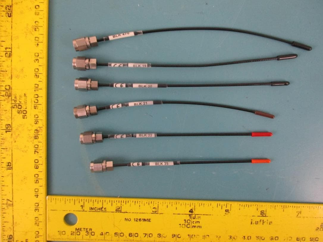
DBZDBSMA
Jan 25, 2021Digital Wireless Microphone Transmitter
Equipment Class
TLD - Licensed LPAS Device
DBZSMWB79
Jul 20, 2020Body-worn Wireless Microphone Transmitters
Equipment Class
TLD - Licensed LPAS Device