DBZSMV79Wireless Microphone Transmitter
Lectrosonics Inc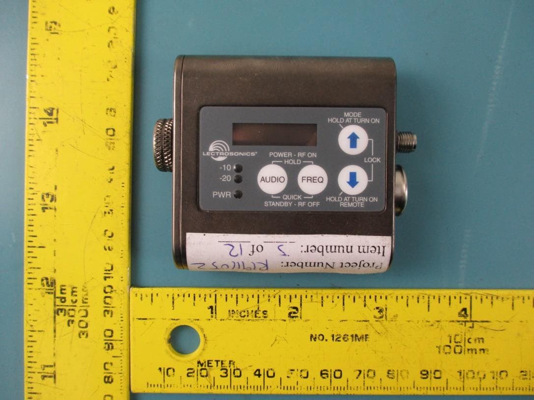
Click to zoom
Application Details
- Equipment Class
- TLD - Licensed LPAS Device
- Date of Grant
- Feb 19, 2020
- Application Purpose
- Original Equipment
- Date of Application
- Feb 19, 2020
- Equipment Note
- Wireless Microphone Transmitter
- Frequency Range
- 956.47500000 - 959.82500000
- Company
- Lectrosonics Inc
- Country
- United States
Documents & Files
Document Text
Text extracted from the exhibit documents filed with the FCC. Open a document above to read the original.
Users Manual
SMV Series Super Miniature Variable Power Transmitters With Digital Hybrid Wireless ® Technology SMQV Dual Battery Model SMQV-941 Dual Battery Model SMQV/E07-941 Dual Battery Model SMQV/X Dual Battery Model SMV Single Battery Model SMV-941 Single Battery Model SMV/E07-941 Single Battery Model SMV/X Single Battery Model INSTRUCTION MANUAL Rio Rancho, NM, USA www.lectrosonics.com Fill in for your records: Serial Number: Purchase Date: US Patent 7,225,135 SMV Series LECTROSONICS, INC. 2 Introduction The SM Series variable power transmitters are the product of many years of engineering and experience in professional audio markets. The unique design provides several distinct features for professional applications: • Selectable output power to maximize battery life or operating range as needed • Superb, compandor-free audio quality • Ultra-lightweight, corrosion resistant housing • Water resistant seals for use in damp environments • Programmable compatibility modes for use with a wide variety of different receivers The Digital Hybrid Wireless ® design (US Patent 7,225,135) combines 24-bit digital audio with analog FM resulting in a system that has the same operating range as analog systems, the same spectral efficiency as analog systems, the same long battery life as analog systems, plus the excellent audio fidelity typical of pure digital systems. The SM Series transmitters feature the unique servo bias input circuitry with a standard TA5M type input jack for use with electret lavaliere mics, dynamic mics, or line level signals. A water resistant control panel with LCD, membrane switches and multi-color LEDs make input gain adjustments, frequency and compatibility mode selection quick and accurate, without having to view the receiver. The battery compartment accepts AA lithium or rechargeable batteries. The housings are machined from solid aluminum blocks to provide an extremely lightweight and rugged package. A special non-corrosive finish resists salt water exposure and perspiration in extreme environments. FCC Notice: For body worn operation, this transmitter model has been tested and meets the FCC RF exposure guidelines when used with the Lectrosonics accessories sup- plied or designated for this product. Use of other accessories may not ensure compliance with FCC RF exposure guidelines. Contact Lectrosonics if you have any questions or need more information about RF exposure using this product. FCC Compliance: This device complies with FCC radiation exposure limits as set forth for an un- controlled environment. This device should be installed and operated so that its antenna(s) are not co-located or operating in conjunction with any other antenna or transmitter. Super-Minature Belt Pack Transmitter Rio Rancho, NM 3 Table of Contents Introduction ...........................................................................2 General Technical Description ............................................4 Controls and Functions .......................................................6 LCD Screen ........................................................................6 Power LED ..........................................................................6 Power LED Off Feature .......................................................6 Audio Input Jack ..................................................................6 Modulation LEDs .................................................................6 AUDIO Button .....................................................................6 FREQ Button .......................................................................6 Up/Down Arrows .................................................................6 Battery and Battery Eliminator Installation ........................7 Attaching and Removing the Microphone ..........................7 Operating Instructions .........................................................8 Power Up and Boot Sequence ............................................8 Power Down ........................................................................8 Standby Mode .....................................................................8 LCD Backlight Settings .......................................................8 Selecting the Compatibility Modeand Output Power ...........8 Audio Screen ......................................................................9 Frequency Screen ...............................................................9 Lock/Unlock Screen ............................................................9 Remote Control Operation ..................................................9 Industry Canada Compliance: This device operates on a no-protection no-interference basis. Should the user seek to obtain protection from other radio services operating in the same TV bands, a radio license is required. Please consult Industry Canada’s document CPC-2-1-28, Optional Licensing for Low-Power Radio Apparatus in the TV Bands, for details. This device complies with Industry Canada license-exempt RSS standard(s). Op- eration is subject to the following two conditions: 1. This device may not cause harmful interference; 2. This device must accept any interference received, including interference that may cause undesired operation of the device. Cet appareil est conforme à Industrie Canada une licence standard RSS exonérés (s). Son fonctionnement est soumis aux deux conditions suivantes: 1. Cet appareil ne doit pas provoquer d’interférences 2. Cet appareil doit accepter toute interférence reçue, y compris les interférences pouvant provoquer un fonctionnement indésirable de l’appareil Configuring for Power Restore ............................................10 Setting Transmitter Operating Frequency ............................10 Set Up in 100 kHz Mode .....................................................10 Set Up in 25 kHz Mode .......................................................10 Adjusting Audio Level (Gain) ...............................…
Text truncated - open the document above for the full version.
External Photos
Lectrosonics, Inc. FCC ID: DBZSMV79, IC: 8024A-SMV79 EUT External Photographs 1.1. EUT(SMV/E07-941) Top View 1.2. EUT(SMV/E07-941) Bottom View Lectrosonics, Inc. FCC ID: DBZSMV79, IC: 8024A-SMV79 1.3. EUT(SMV/E07-941) Side View #1 1.4. EUT(SMV/E07-941) Side View #2 Lectrosonics, Inc. FCC ID: DBZSMV79, IC: 8024A-SMV79 1.5. EUT(SMV/E07-941) Side View #3 1.6. EUT(SMV/E07-941) Side View #4 Lectrosonics, Inc. FCC ID: DBZSMV79, IC: 8024A-SMV79 1.7. EUT(SMQV/E07-941) Top View 1.8. EUT(SMQV/E07-941) Bottom View Lectrosonics, Inc. FCC ID: DBZSMV79, IC: 8024A-SMV79 1.9. EUT(SMQV/E07-941) Side View #1 1.10. EUT(SMQV/E07-941) Side View #2 Lectrosonics, Inc. FCC ID: DBZSMV79, IC: 8024A-SMV79 1.11. EUT(SMQV/E07-941) Side View #3 1.12. EUT(SMQV/E07-941) Side View #4
Internal Photos
Lectrosonics, Inc. FCC ID: DBZSMV79, IC: 8024A-SMV79 EUT Internal Photographs 1.1 EUT PCB#1 Top View 1.2 EUT PCB#1 Bottom View Lectrosonics, Inc. FCC ID: DBZSMV79, IC: 8024A-SMV79 1.3 EUT PCB#2 Top View 1.4 EUT PCB#2 Bottom View
RF Exposure Info
Note: This test report is prepared for the customer shown above and for the device described herein. It may not be duplicated or used in part without prior written consent from Bay Area Compliance Laboratories Corp. (Dongguan). This report must not be used by the customer to claim product certification, approval, or endorsement by A2LA* or any agency of the Federal Government. * This report may contain data that are not covered by the A2LA accreditation and are marked with an asterisk “*”. SAR EVALUATION REPORT For Lectrosonics, Inc. 581 Laser Rd NE Rio Rancho NM 87124, USA FCC ID: DBZSMV79 IC: 8024A-SMV79 Report Type: Original Report Product Type: Body-worn wireless microphone transmitter Report Number: R1911052-20 Report Date: 2019-12-18 Reviewed By: Rocky Xiao RF Engineer Prepared By: Bay Area Compliance Laboratories Corp. (Dongguan) No.69 Pulongcun, Puxinhu Industry Area, Tangxia, Dongguan, Guangdong, China Tel: +86-769-86858888 Fax: +86-769-86858891 www.baclcorp.com.cn Bay Area Compliance Laboratories Corp. (Dongguan) Report No.: R1911052-20 SAR Evaluation Report 2 of 34 Attestation of Test Results EUT Information EUT Description Body-worn wireless microphone transmitter Tested Model SMQV/E07-941, SMV/E07-941 FCC ID DBZSMV79 IC 8024A-SMV79 Serial Number 2 Test Date 2019-11-14 MODE Max. SAR Level(s) Reported(W/kg) Limit (W/kg) FM (941.525-959.825 MHz) SMQV/E07-941 1g Body SAR 1.38 1.6 SMV/E07-941 1g Body SAR 1.42 Applicable Standards FCC 47 CFR part 2.1093 Radiofrequency radiation exposure evaluation: portable devices RSS-102 Issue 5 March 2015 Radio Frequency (RF) Exposure Compliance of Radio communication Apparatus (All Frequenc y Bands). RF Exposure Procedures: TCB Workshop April 2019 IEEE1528:2013 IEEE Recommended Practice for Determining the Peak Spatial-Average Specific Absorption Rate (SAR) in the Human Head from Wireless Communications Devices: Measurement Techniques IEC 62209-2:2010 Human exposure to radio frequency fields from hand-held and body-mounted wireless communication devices-Human models, instrumentation, and procedures-Part 2: Procedure to determine the specific absorption rate (SAR) for wireless communication devices used in close proximit y to the human body (frequencyrange of 30 MHz to 6 GHz) KDB procedures KDB 447498 D01 General RF Exposure Guidance v06 KDB 865664 D01 SAR Measurement 100 MHz to 6 GHz v01r04 KDB 865664 D02 RF Exposure Reportin g v01r02 Note: This wireless device has been shown to be capable of compliance for localized specific absorption rate (SAR) for General Population/Uncontrolled Exposure limits specified in FCC 47 CFR part 2.1093/ RSS-102 Issue 5 March 2015 and has been tested in accordance with the measurement procedures specified in IEEE 1528-2013 and RF exposure KDB procedures. The results and statements contained in this report pertain only to the device(s) evaluated. Bay Area Compliance Laboratories Corp. (Dongguan) Report No.: R1911052-20 SAR Evaluation Report 3 of 34 TABLE OF CONTENTS DOCUMENT REVISION HISTORY ......................................................................................................................... 4 EUT DESCRIPTION .................................................................................................................................................... 5 TECHNICAL SPECIFICATION ......................................................................................................................................... 5 REFERENCE, STANDARDS, AND GUIDELINES .................................................................................................. 6 SAR LIMITS ................................................................................................................................................................. 7 FACILITIES .................................................................................................................................................................. 8 DESCRIPTION OF TEST SYSTEM .......................................................................................................................... 9 EQUIPMENT LIST AND CALIBRATION ............................................................................................................. 15 EQUIPMENTS LIST & CALIBRATION INFORMATION .................................................................................................... 15 SAR MEASUREMENT SYSTEM VERIFICATION .............................................................................................. 16 LIQUID VERIFICATION ............................................................................................................................................... 16 SYSTEM ACCURACY VERIFICATION ........................................................................................................................... 17 SAR SYSTEM VALIDATION DATA ..................................................................................................................... 18 EUT TEST STRATEGY AND METHODOLOGY ................................................................................................. 19 TEST POSITIONS FOR DEVICE OPERATING NEXT TO A PERSON’S EAR........................................................................ 19 CHEEK/TOUCH POSITION ........................................................................................................................................... 20 EAR/TILT POSITION ................................................................................................................................................... 20 TEST POSITIONS FOR BODY-WORN AND OTHER CONFIGURATIONS .............................................................................. 21 TEST DISTANCE FOR SAR EVALUATION .................................................................................................................... 21 SAR EVALUATION PROCEDURE .........................................................................…
Text truncated - open the document above for the full version.
RF Exposure Info
APPENDIX C PROBE CALIBRATION CERTIFICATES DIPOLE CALIBRATION CERTIFICATES
RF Exposure Info
Report No.: R1911052-20 Page 1 of 6 Test Plot 1#: 941.525MHz_Rear Side Touch DUT: Body-worn wireless microphone transmitter; Type: SMQV/E07-941; Serial: 2 Communication System: FM; Frequency: 941.525 MHz;Duty Cycle: 1:1 Medium parameters used: f = 941.525 MHz; σ = 0.975 S/m; ε r = 39.945; ρ = 1000 kg/m 3 Phantom section: Flat Section DASY5 Configuration: • Probe: EX3DV4 - SN7441; ConvF(9.69, 9.69, 9.69) @ 941.525 MHz; Calibrated: 2018/12/13 • Sensor-Surface: 1.4mm (Mechanical Surface Detection) • Electronics: DAE3 Sn471; Calibrated: 2018/12/3 • Phantom: SAM (30deg probe tilt) with CRP v5.0_20150321; Type: QD000P40CD; Serial: TP:1874 • Measurement SW: DASY52, Version 52.10 (2); SEMCAD X Version 14.6.12 (7470) Area Scan (71x121x1): Interpolated grid: dx=1.500 mm, dy=1.500 mm Maximum value of SAR (interpolated) = 1.64 W/kg Zoom Scan (5x5x7)/Cube 0: Measurement grid: dx=8mm, dy=8mm, dz=5mm Reference Value = 26.28 V/m; Power Drift = -0.06 dB Peak SAR (extrapolated) = 1.99 W/kg SAR(1 g) = 0.962 W/kg; SAR(10 g) = 0.537 W/kg Maximum value of SAR (measured) = 1.56 W/kg 0 dB = 1.56 W/kg = 1.93 dBW/kg Report No.: R1911052-20 Page 2 of 6 Test Plot 2#: 950.675 MHz_Rear Side Touch DUT: Body-worn wireless microphone transmitter; Type: SMQV/E07-941; Serial: 2 Communication System: FM; Frequency: 950.675 MHz;Duty Cycle: 1:1 Medium parameters used: f = 950.675 MHz; σ = 0.988 S/m; ε r = 39.894; ρ = 1000 kg/m 3 Phantom section: Flat Section DASY5 Configuration: • Probe: EX3DV4 - SN7441; ConvF(9.69, 9.69, 9.69) @ 950.675 MHz; Calibrated: 2018/12/13 • Sensor-Surface: 1.4mm (Mechanical Surface Detection) • Electronics: DAE3 Sn471; Calibrated: 2018/12/3 • Phantom: SAM (30deg probe tilt) with CRP v5.0_20150321; Type: QD000P40CD; Serial: TP:1874 • Measurement SW: DASY52, Version 52.10 (2); SEMCAD X Version 14.6.12 (7470) Area Scan (71x121x1): Interpolated grid: dx=1.500 mm, dy=1.500 mm Maximum value of SAR (interpolated) = 1.57 W/kg Zoom Scan (5x5x7)/Cube 0: Measurement grid: dx=8mm, dy=8mm, dz=5mm Reference Value = 28.83 V/m; Power Drift = -0.03 dB Peak SAR (extrapolated) = 1.99 W/kg SAR(1 g) = 1.03 W/kg; SAR(10 g) = 0.595 W/kg Maximum value of SAR (measured) = 1.62 W/kg 0 dB = 1.62 W/kg = 2.10 dBW/kg Report No.: R1911052-20 Page 3 of 6 Test Plot 3#: 959.825 MHz_Rear Side Touch DUT: Body-worn wireless microphone transmitter; Type: SMQV/E07-941; Serial: 2 Communication System: FM; Frequency: 959.825 MHz;Duty Cycle: 1:1 Medium parameters used: f = 959.825 MHz; σ = 1.003 S/m; ε r = 39.811; ρ = 1000 kg/m 3 Phantom section: Flat Section DASY5 Configuration: • Probe: EX3DV4 - SN7441; ConvF(9.69, 9.69, 9.69) @ 959.825 MHz; Calibrated: 2018/12/13 • Sensor-Surface: 1.4mm (Mechanical Surface Detection) • Electronics: DAE3 Sn471; Calibrated: 2018/12/3 • Phantom: SAM (30deg probe tilt) with CRP v5.0_20150321; Type: QD000P40CD; Serial: TP:1874 • Measurement SW: DASY52, Version 52.10 (2); SEMCAD X Version 14.6.12 (7470) Area Scan (71x121x1): Interpolated grid: dx=1.500 mm, dy=1.500 mm Maximum value of SAR (interpolated) = 1.81 W/kg Zoom Scan (5x5x7)/Cube 0: Measurement grid: dx=8mm, dy=8mm, dz=5mm Reference Value = 34.31 V/m; Power Drift = -0.02 dB Peak SAR (extrapolated) = 2.51 W/kg SAR(1 g) = 1.33 W/kg; SAR(10 g) = 0.765 W/kg Maximum value of SAR (measured) = 2.07 W/kg 0 dB = 2.07 W/kg = 3.16 dBW/kg Report No.: R1911052-20 Page 4 of 6 Test Plot 4#: 941.525 MHz_Rear Side Touch DUT: Body-worn wireless microphone transmitter; Type: SMV/E07-941; Serial: 2 Communication System: FM; Frequency: 941.525 MHz;Duty Cycle: 1:1 Medium parameters used: f = 941.525 MHz; σ = 0.975 S/m; ε r = 39.945; ρ = 1000 kg/m 3 Phantom section: Flat Section DASY5 Configuration: • Probe: EX3DV4 - SN7441; ConvF(9.69, 9.69, 9.69) @ 941.525 MHz; Calibrated: 2018/12/13 • Sensor-Surface: 1.4mm (Mechanical Surface Detection) • Electronics: DAE3 Sn471; Calibrated: 2018/12/3 • Phantom: SAM (30deg probe tilt) with CRP v5.0_20150321; Type: QD000P40CD; Serial: TP:1874 • Measurement SW: DASY52, Version 52.10 (2); SEMCAD X Version 14.6.12 (7470) Area Scan (71x121x1): Interpolated grid: dx=1.500 mm, dy=1.500 mm Maximum value of SAR (interpolated) = 2.00 W/kg Zoom Scan (5x5x7)/Cube 0: Measurement grid: dx=8mm, dy=8mm, dz=5mm Reference Value = 31.97 V/m; Power Drift = -0.15 dB Peak SAR (extrapolated) = 2.40 W/kg SAR(1 g) = 1.23 W/kg; SAR(10 g) = 0.692 W/kg Maximum value of SAR (measured) = 1.88 W/kg 0 dB = 1.88 W/kg = 2.74 dBW/kg Report No.: R1911052-20 Page 5 of 6 Test Plot 5#: 950.675 MHz_Rear Side Touch DUT: Body-worn wireless microphone transmitter; Type: SMV/E07-941; Serial: 2 Communication System: FM; Frequency: 950.675 MHz;Duty Cycle: 1:1 Medium parameters used: f = 950.675 MHz; σ = 0.988 S/m; ε r = 39.894; ρ = 1000 kg/m 3 Phantom section: Flat Section DASY5 Configuration: • Probe: EX3DV4 - SN7441; ConvF(9.69, 9.69, 9.69) @ 950.675 MHz; Calibrated: 2018/12/13 • Sensor-Surface: 1.4mm (Mechanical Surface Detection) • Electronics: DAE3 Sn471; Calibrated: 2018/12/3 • Phantom: SAM (30deg probe tilt) with CRP v5.0_20150321; Type: QD000P40CD; Serial: TP:1874 • Measurement SW: DASY52, Version 52.10 (2); SEMCAD X Version 14.6.12 (7470) Area Scan (71x121x1): Interpolated grid: dx=1.500 mm, dy=1.500 mm Maximum value of SAR (interpolated) = 1.82 W/kg Zoom Scan (5x5x7)/Cube 0: Measurement grid: dx=8mm, dy=8mm, dz=5mm Reference Value = 36.82 V/m; Power Drift = -0.16 dB Peak SAR (extrapolated) = 2.66 W/kg SAR(1 g) = 1.38 W/kg; SAR(10 g) = 0.771 W/kg Maximum value of SAR (measured) = 2.16 W/kg 0 dB = 2.16 W/kg = 3.34 dBW/kg Report No.: R1911052-20 Page 6 of 6 Test Plot 6#: 959.825 MHz_Rear Side Touch DUT: Body-worn wireless microphone transmitter; Type: SMV/E07-941; Serial: 2 Communication System: FM; Frequency: 959.825 MHz;Duty Cycle: 1:1 Medium parameters used: f = 959.825 MHz; σ = 1.003 S/m; ε r = 39.811; ρ = 1000 kg/m 3 Phantom section: Flat Section DASY5 Configuration: • Probe: EX3DV4 - SN7441; ConvF(9.69, 9.69, 9.69) @ 959.825 MHz; Calibrated: 2018/12/13 • Sensor-Surface:…
Text truncated - open the document above for the full version.
Test Report
Note: This test report is prepared for the customer shown above and for the device described herein. It may not be duplicated or used in part without prior written consent from Bay Area Compliance Laboratories Corp. This report must not be used by the customer to claim product certification, approval, or endorsement by A2LA*, NIST, or any agency of the Federal Government. * This report may contain data that are not covered by the A2LA accreditation and are marked with an asterisk “*” (Rev.2) FCC PART 74, SUBPART H ISEDC RSS-123, ISSUE 4 TEST AND MEASUREMENT REPORT For Lectrosonics, Inc. 581 Laser Road NE, Rio Rancho, NM 87124, USA FCC ID: DBZSMV79 IC: 8024A-SMV79 Report Type: Original Report Product Type: Wireless Microphone Transmitter Prepared By: Christian McCaig Test Engineer Report Number R1911052-74 Report Issue Date: 2020-01-22 Reviewed By: Simon Ma RF Supervisor Bay Area Compliance Laboratories Corp. 1274 Anvilwood Avenue, Sunnyvale, CA 94089, USA Tel: +1 (408) 732-9162, Fax: +1 (408) 732-9164 Lectrosonics, Inc. FCC ID: DBZSMV79, IC: 8024A-SMV79 Report Number: R1911052-74 Page 2 of 43 FCC Part 74/ISEDC RSS-123 Test Report TABLE OF CONTENTS 1 GENERAL DESCRIPTION ................................................................................................................................. 5 1.1 PRODUCT DESCRIPTION FOR EQUIPMENT UNDER TEST (EUT) .......................................................................... 5 1.2 MECHANICAL DESCRIPTION OF EUT ................................................................................................................. 5 1.3 OBJECTIVE ......................................................................................................................................................... 5 1.4 RELATED SUBMITTAL(S)/GRANT(S) ................................................................................................................... 5 1.5 TEST METHODOLOGY ........................................................................................................................................ 5 1.6 MEASUREMENT UNCERTAINTY .......................................................................................................................... 6 1.7 TEST FACILITY REGISTRATIONS ........................................................................................................................ 6 1.8 TEST FACILITY ACCREDITATIONS ...................................................................................................................... 7 2 EUT TEST CONFIGURATION ........................................................................................................................... 9 2.1 JUSTIFICATION ................................................................................................................................................... 9 2.2 EUT EXERCISE SOFTWARE ................................................................................................................................ 9 2.3 SPECIAL EQUIPMENT ......................................................................................................................................... 9 2.4 EQUIPMENT MODIFICATIONS ............................................................................................................................. 9 2.5 LOCAL SUPPORT EQUIPMENT............................................................................................................................. 9 2.6 INTERFACE PORTS AND CABLES ........................................................................................................................ 9 3 SUMMARY OF TEST RESULTS ...................................................................................................................... 10 4 FCC §2.1093 & ISEDC RSS-102 - RF EXPOSURE ......................................................................................... 11 5 FCC §74.861(D)(1) & ISEDC RSS-123 §8.2 - RF OUTPUT POWER ............................................................ 12 5.1 APPLICABLE STANDARDS ................................................................................................................................ 12 5.2 TEST PROCEDURE ............................................................................................................................................ 12 5.3 TEST EQUIPMENT LIST AND DETAILS .............................................................................................................. 13 5.4 TEST ENVIRONMENTAL CONDITIONS ............................................................................................................... 13 5.5 TEST RESULTS ................................................................................................................................................. 13 6 FCC §2.1049, §74.861(D)(4)(I) & ISEDC RSS123 §8.2 , §8.3 - OCCUPIED BANDWIDTH & EMISSION MASK 17 6.1 APPLICABLE STANDARDS ................................................................................................................................ 17 6.2 TEST PROCEDURE ............................................................................................................................................ 18 6.3 TEST EQUIPMENT LIST AND DETAILS .............................................................................................................. 18 6.4 TEST ENVIRONMENTAL CONDITIONS ............................................................................................................... 18 6.5 TEST RESULTS ................................................................................................................................................. 18 7 FCC §74.861(D)(4)(I) & ISEDC RSS-123 §8.3 - CONDUCTED SPURIOUS EMISSIONS AT ANTENNA PORT 22 7.1 APPLICABLE STANDARDS ................................................................................................................................ 22 7.2 TEST PROCEDURE ....…
Text truncated - open the document above for the full version.
Test Setup Photos
Lectrosonics, Inc. FCC ID: DBZSMV79, IC: 8024A-SMV79 Report Number: R1911052-74 Page 1 of 2 FCC Part 74/ISED RSS-123 Test Report EUT Test Setup Photographs 1.1. EUT Test Setup Rear View (Above 1GHz) 1.2. EUT Test Setup Front View (Above 1GHz) Lectrosonics, Inc. FCC ID: DBZSMV79, IC: 8024A-SMV79 Report Number: R1911052-74 Page 2 of 2 FCC Part 74/ISED RSS-123 Test Report 1.3. EUT Test Setup Rear View (Below 1GHZ) 1.4. EUT Test Setup Front View (Below 1GHZ)
Test Setup Photos
Report No.: R1911052-20 Page 1 of 2 APPENDIX B EUT TEST POSITION PHOTOS Liquid depth ≥ 15cm Phantom: SAM (30deg probe tilt) with CRP v5.0_20150321; Type: QD000P40CD; Serial: TP:1874 Report No.: R1911052-20 Page 2 of 2 Rear Side Touch_SMQV/E07-941 Rear Side Touch_SMV/E07-941
Contact Information
Applicant
Robert Cunnings(Vice President, Engineering)
Test Firm
Bay Area Compliance Laboratories Corp.Lisa Tang
Technical Specifications
| # | Rule Parts | Frequency Range | Power Output | Emission | Tolerance |
|---|---|---|---|---|---|
| 3 | 74H | 956.475 MHz - 959.825 MHz | 100.00 mW | 110KF3E | 20 ppm |
Other Applications from Lectrosonics Inc
DBZT20A
Jun 05, 2026Digital Hybrid Wireless microphone transmitter
Equipment Class
TLD - Licensed LPAS DeviceDBZT20B
Jun 05, 2026Digital Hybrid Wireless microphone transmitter
Equipment Class
TLD - Licensed LPAS DeviceDBZDCHTB
Sep 08, 2024Digital Camera Hop Transmitter
Equipment Class
DWM - Part 15 Wireless Microphone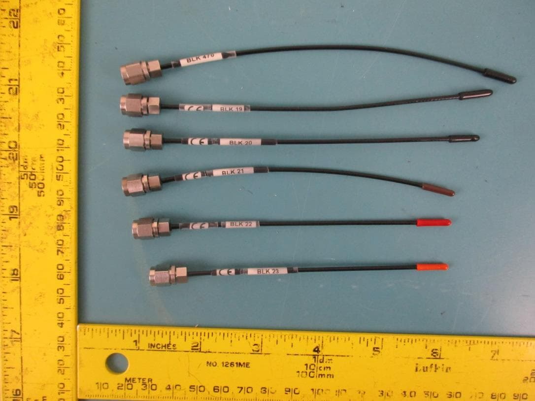
DBZDBSMA
Jan 25, 2021Digital Wireless Microphone Transmitter
Equipment Class
TLD - Licensed LPAS Device
DBZSMWB79
Jul 20, 2020Body-worn Wireless Microphone Transmitters
Equipment Class
TLD - Licensed LPAS Device