DBZUM400EWIRELESS MICROPHONE TRANSMITTER
Lectrosonics Inc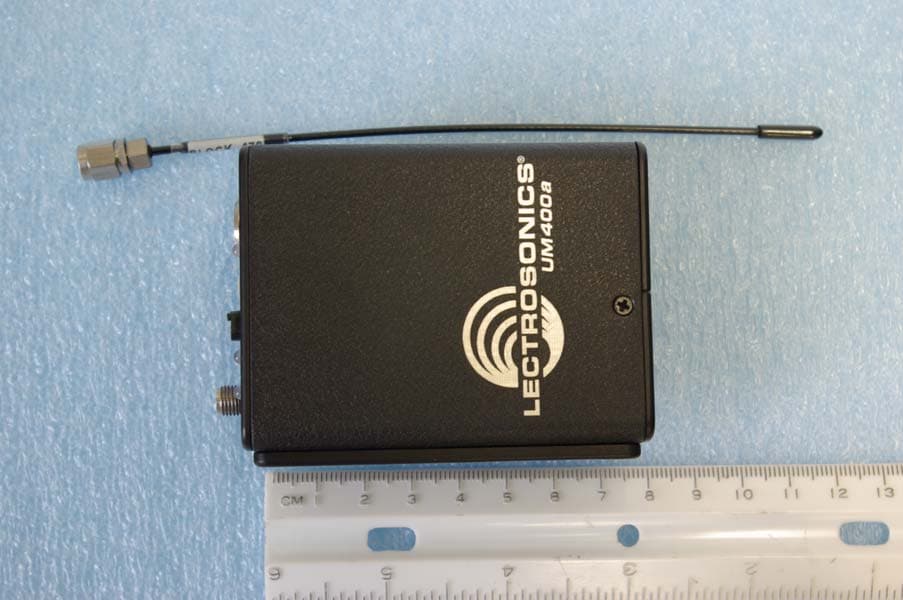
Click to zoom
Application Details
- Equipment Class
- TBT - Licensed Broadcast Transmitter Worn on Body
- Date of Grant
- Apr 15, 2008
- Application Purpose
- Original Equipment
- Date of Application
- Apr 15, 2008
- Equipment Note
- WIRELESS MICROPHONE TRANSMITTER
- Frequency Range
- 470.10000000 - 537.50000000
- Company
- Lectrosonics Inc
- Country
- United States
Documents & Files
Document Text
Text extracted from the exhibit documents filed with the FCC. Open a document above to read the original.
Users Manual
UM400a Frequency Synthesized 100 mW UHF Belt-Pack Transmitter INSTRUCTION MANUAL Rio Rancho, NM, USA www.lectrosonics.com Fill in for your records: Serial Number: Purchase Date: Featuring Digital Hybrid Wireless ™ Technology U.S. Patent 7,225,235 UM400a LECTROSONICS, INC. 2 Frequency Synthesized UHF Belt-Pack Transmitter Rio Rancho, NM 3 © Copyright 2008 Lectrosonics. Inc Table of Contents General Technical Description ..............................................................................................................................................................4 Introduction ...........................................................................................................................................................................................4 Digital Hybrid Technology......................................................................................................................................................................4 UM400a Block Diagram ........................................................................................................................................................................4 No Pre-Emphasis/De-Emphasis ...........................................................................................................................................................5 Pilot Tone Squelch ................................................................................................................................................................................5 Input Limiter ..........................................................................................................................................................................................5 Wide-Band Deviation ............................................................................................................................................................................5 Frequency Selection .............................................................................................................................................................................5 Controls and Functions .........................................................................................................................................................................6 Input Jack ..............................................................................................................................................................................................6 Power ON/OFF Switch ..........................................................................................................................................................................6 Power On LED ......................................................................................................................................................................................6 Frequency Select Switches ...................................................................................................................................................................6 Audio Level Control ...............................................................................................................................................................................7 Modulation LEDs ...................................................................................................................................................................................7 Antenna .................................................................................................................................................................................................7 Adjustable Low Frequency Roll-Off .......................................................................................................................................................7 Belt Clip .................................................................................................................................................................................................7 Battery Installation .................................................................................................................................................................................8 Operating Instructions ...........................................................................................................................................................................8 Selecting the Compatibility Mode ..........................................................................................................................................................8 Attaching a Microphone and Adjusting Gain .........................................................................................................................................9 Operating Notes ....................................................................................................................................................................................9 Adjusting the Transmitter Frequency .....................................................................................................................................................9 5-Pin Input Jack Wiring ........................................................................................................................................................................10 Microphone Cable Terminationfor Non-Lectrosonics Microphones ................................................................................................11 TA5F Connector Assembly .................................................................................................................................................................11 Mic Cord Stripping Instructions ...........................................................................................................................................................11 Crimping…
Text truncated - open the document above for the full version.
Cover Letter(s)
April 11, 2008 Office of Engineering and Technology Federal Communications Commission Columbia, MD 21046 Applicant: Lectrosonics, Inc. 581 Laser Road Rio Rancho, NM 87124 Re: Confidentiality for submittal information regarding FCC ID number DBZUM400E PRODUCT: Wireless Microphone transmitter operating under part 74. Dear Sirs: Lectrosonics, Inc. requests that the material in the Parts List, Block Diagram, Schematics, and Operational Description be withheld from public disclosure in accordance with Section 0.459 of the Commissions Rules, 47 C.F.R. 0.459 (1998), following grant of the application. In support of this request, Lectrosonics, Inc. submits the following. Short term confidential files External Photographs ExtPho DBZUM400E.pdf Internal Photographs IntPho DBZUM400E.pdf Test Setup TSup DBZUM400E.pdf User Manual UserMan DBZUM400E.pdf Permanent Confidential files Block Diagram Conf BlkDia DBZUM400E.pdf Parts List Conf PartList DBZUM400E.pdf Operational Description Conf OpDes DBZUM400E.pdf Schematic Conf Schem DBZUM400E.pdf 1. Identification of the specific information for which confidential treatment is sought: The materials set fourth in the Operational Description, Parts List, block diagram, and Schematics, which are segregated from the non-confidential exhibits of the application, are those for which confidentiality is sought. 2. Identification of the Commission proceeding in which the information was submitted or a description of the circumstances giving rise to the submission: The proceeding is that involving the application for equipment authorization (certification) under FCC ID: DBZUM400E ROGERS LABS, INC. 4405 West 259 th Terrace Louisburg, KS 66053 3. Explanation of the degree to which the information is commercial or financial, or contains a trade secret or is privileged: This material includes a detailed theory of operation, circuit diagrams, (schematic diagrams) and detailed Parts List. As such, this material is treated as highly confidential business information. 4. Explanation of the degree to which the information concerns a service that is subject to competition: The material for which confidentiality is sought is employed in the design and manufacture of this transmitting equipment that is offered on a highly competitive basis. Customers for this equipment have a variety of competing sources. 5. Explanation of how disclosure of the information could result in substantial competitive harm: Disclosure would, in effect, give away the fruits of the labors of Lectrosonics, Inc.’s engineering personnel, who have designed the equipment and the manufacturing process. Disclosure would also offer competitors additional unwarranted insight into the state of the product development, thereby allowing competitors an advantage, not available to Lectrosonics, Inc. 6. Identification of any measures taken by the submitting party to prevent unauthorized disclosure: The information for which confidential treatment is sought is kept confidential by Lectrosonics, Inc. and not made available to third parties except pursuant to non-disclosure agreements. 7. Identification of whether the information is available to the public and the extent of any previous disclosure of the information to third parties: To the knowledge of those preparing this application, the information has not been disclosed publicly heretofore. While the general theory of operation of this equipment has been the subject of numerous disclosures in industry and standards groups as well as in rule making proceedings of the FCC, the protection sought is narrowly drawn and pertains to certain specific implementations of this radio technology. 8. Justification of the period during which the submitting party asserts that the material should not be available for public disclosure: This material should not be disclosed for at least 25 years. While improvements in design are made relatively frequently, disclosure of the design information would lead to insights into both design and manufacturing techniques that could have an adverse competitive effect for many years to come. This equipment is designed for commercial, industrial, and governmental applications. As such, unlike most consumer equipment, this equipment could be used for more than a decade in some cases. As such, it is important that the design not be made available to unauthorized persons who might attempt to use knowledge of the design to compromise the applications for which the equipment will be employed. Should you require any further information, please contact the undersigned. Thank you for your consideration in this matter. Sincerely, Scot Rogers
Cover Letter(s)
April 11, 2008 Office of Engineering and Technology Federal Communications Commission Columbia, MD 21046 Applicant: Lectrosonics, Inc. 581 Laser Road Rio Rancho, NM 87124 Re: Short-term Confidentiality request for submittal information regarding FCC ID DBZUM400E PRODUCT: Wireless Microphone transmitter operating under part 74. Dear Sirs: Lectrosonics, Inc. requests that the following information be withheld from public disclosure until 45 days after the Grant of Equipment Authorization in accordance with DA-04-1705 of the Commission’s public notice. Short term confidential files External Photographs ExtPho DBZUM400E.pdf Internal Photographs IntPho DBZUM400E.pdf Test Setup TSup DBZUM400E.pdf User Manual UserMan DBZUM400E.pdf Permanent Confidential files Block Diagram Conf BlkDia DBZUM400E.pdf Parts List Conf PartList DBZUM400E.pdf Operational Description Conf OpDes DBZUM400E.pdf Schematics Conf Schem DBZUM400E.pdf Should you require any further information, please contact the undersigned. Thank you for your consideration in this matter. Sincerely, Scot Rogers ROGERS LABS, INC. 4405 West 259 th Terrace Louisburg, KS 66053
Cover Letter(s)
April 11, 2008 Federal Communications Commission Equipment Approval Services Post Office Box 358315 Pittsburgh, Pennsylvania 15215-5315 To Whom It May Concern: Please be advised that Lectrosonics. Inc. has authorized Scot Rogers of Rogers Labs. Inc. to act on behalf in all matters relating to application for equipment authorization, including the signing of all documents relating to these matters and submittals. All acts carried out by Rogers Labs. Inc. on our behalf shall have the same effects as our own. Rogers Labs, Inc. is authorized to receive and exchange data between our company and the Commission. This Authorization is made pursuant to Paragraph 2.911 of FCC Rules CFR47. This Authorization is in effect until otherwise notified in writing. President Lectrosonics, Inc.
Cover Letter(s)
April 11, 2008 Federal Communications Commission Equipment Approval Services P.O. Box 35815 Pittsburgh, PA 15251-3315 Applicant: Lectrosonics, Inc. 581 Laser Road Rio Rancho, NM 87124 Equipment: FCC ID: DBZUM400E FCC Rules: Part 2 and 74 The 731 form and application have been electronically submitted and any attachments will be up loaded to your web site to be used in obtaining a grant of certification. It is requested that the information contained in the Block Diagram, Parts List, Operational Description, and Schematics of the application be held confidential per Section 0.459. A statement of confidentiality will be attached with the application at the time of submittal. Short Term Confidential Request Pursuant to DA 04-1705 of the Commission’s pubic notice, we request short-term confidential treatment for the following information until 45 days after the Grant Date of Equipment Authorization in order to ensure sensitive business information remains confidential until the actual marketing of the device: Short term confidential files External Photographs ExtPho DBZUM400E.pdf Internal Photographs IntPho DBZUM400E.pdf Test Setup TSup DBZUM400E.pdf User Manual UserMan DBZUM400E.pdf Permanent Confidential Request Lectrosonics Inc. requests that the material in the Parts List, Schematics, block diagram, and Operational Description be withheld from public disclosure in accordance with Section 0.459 of the Commissions Rules, CFR47 0.459, following grant of the application. It is requested that the information contained in the operational description, block diagram, parts list, and schematics of the application be held confidential per Section 0.459. A statement of confidentiality will be attached with the application at the time of submittal. Permanent Confidential files Block Diagram Conf BlkDia DBZUM400E.pdf Parts List Conf PartList DBZUM400E.pdf Operational Description Conf OpDes DBZUM400E.pdf Schematics Conf Schem DBZUM400E.pdf Should you require any further information, please contact the undersigned. Thank you for your consideration in this matter. Sincerely, Scot Rogers Rogers Labs, Inc. Enclosures ROGERS LABS, INC. 4405 West 259 th Terrace Louisburg, KS 66053 Phone / Fax (913) 837-3214
External Photos
Rogers Labs, Inc. Lectrosonics, Inc. 4405 W. 259th Terrace Model: UM400A FCC ID#: DBZUM400E Louisburg, KS 66053 Test #: 080313A SN: P496 Phone/Fax: (913) 837-3214 Test to: FCC Parts 2 and 74 Page 1 of 3 File: ExtPho DBZUM400E Date: April 9, 2008 Photographs of Equipment Rogers Labs, Inc. Lectrosonics, Inc. 4405 W. 259th Terrace Model: UM400A FCC ID#: DBZUM400E Louisburg, KS 66053 Test #: 080313A SN: P496 Phone/Fax: (913) 837-3214 Test to: FCC Parts 2 and 74 Page 2 of 3 File: ExtPho DBZUM400E Date: April 9, 2008 Rogers Labs, Inc. Lectrosonics, Inc. 4405 W. 259th Terrace Model: UM400A FCC ID#: DBZUM400E Louisburg, KS 66053 Test #: 080313A SN: P496 Phone/Fax: (913) 837-3214 Test to: FCC Parts 2 and 74 Page 3 of 3 File: ExtPho DBZUM400E Date: April 9, 2008
ID Label/Location Info
FREQUENCY 1.6MHz 100kHz 0 1 2 3 4 5 6 7 8 9 A B C D E F 0 1 2 3 4 5 6 7 8 9 A B C D E F SN: XXXX FCCID:DBZUM400E Lectrosonics, Inc. Made in U.S.A. 35 150 75 Hz LF ROLL OFF MODES: 100, 200, MODE 3, 400, MODE 6 Belt clip side INOP FROM 952.0-969.9 (4F-FF) p/o um400asp.dsf PN: 26461-5 10 April 2008 FCC engraving: BL470-20: DBZUM400E BL21-29: DBZUM400 BL944: DBZUM400AV
Parts List/Tune Up Info
TUNE-UP PROCEDURE EQUIPMENT REQUIRED Audio signal generator capable of producing signals of -60 dBV to +10 dBV into 600 ohms at frequencies of 10 Hz to 50 kHz. Used in development: Audio Precision ATS-1. RF spectrum analyzer with sensitivity of -100 dBm or better, a frequency range of 10 MHz to 1.5 GHz or wider, a terminating impedance of 50 ohms, and capability of handling an input level of + 25 dBm without overload or significant distortion. Used in development: Hewlett Packard 8560E. Frequency counter covering 10 MHz to 806 MHz with an accuracy of +/- 100 Hz and readout to the nearest 10 Hz or better. This function may be resident on many higher end spectrum analyzers. Used in development: Boonton 8200 and Hewlett Packard 8560E. Deviation meter capable of measuring frequency deviation from 0 to +/-100 kHz at 470 MHz to 806 MHz with an RF power level of +25 dBm or less in an FM system modulated by audio frequencies from 10 Hz to 50 kHz. The unit should also have a demodulated audio output. Used in development: Boonton Model 8200. Digital multimeter capable of measuring current to at least 400 ma and voltage to 10 VDC with an accuracy of 3% or better. Used in development: Fluke Model 85. Audio analyzer capable of measuring audio distortion to 0.05% or less over a frequency range of at least 10 Hz to 50 kHz. The unit should also have an output of residual distortion to an external measurement device. Used in development: Audio Precision ATS-1. Oscilloscope with good audio response and sensitivity of at least 10 mv/cm with associated high impedance probe is also needed for evaluation of residual distortion. Used in development: Tektronix Model 224. Power supply for bench top use capable of supplying 1.5 VDC at 600 ma of current is needed. Both current and voltage should be metered. The supply should also have a variable current limit adjustment. Used in development: Leader Model LPS-15SL. RF power meter or 50 ohm RF probe and associated meter capable of measuring RF power to 806 MHz at power levels to +25 dBm to an accuracy of 5% is also required. Many higher-end spectrum analyzers have this capability available as part of the cursor functions. Used in development: Hewlett Packard 8560E and Hewlett Packard 437B. AC RMS voltmeter with a range of at least +20 dBV to -60 dBV (10 Vrms to 1 mVrms) readable to within +/- 3% is needed. Used in development: Audio Precision ATS-1. RECOMMENDED TEST FIXTURES An audio cable with a 5 pin Switchcraft plug on one end. The other end should be appropriate to the audio signal generator. Note that DMMs may read inaccurately in RF fields. A 50-Ohm coax cable (RG174) 2 to 3 feet long is necessary to connect the RF output of the- UM400 to the spectrum analyzer and/or frequency counter. One end should be terminated with an SMA. The other end of the coax should be terminated with a BNC male or appropriate connector. GENERAL NOTES The tuning capacitors are small and have a very small tuning socket. An alignment tool, which fits the tuning capacitors, is a must. CHECKING THE POWER INDICATOR Substitute the power supply for the battery. The supply should be current limited to 100 ma to protect the UM400 from shorts and over current due to misalignment. Set the supply for 9 VDC and connect it to the UM400. The current drain should 70 ma or less. When properly aligned this value should be nominally 70 ma (for the combination of audio and RF boards) with only the power LED illuminated. The green battery indicator LED located on the top panel should be brightly lit. Adjust the power supply voltage downward while watching the Power LED. The LED should change to red at 6 volts(TBD). This completes the power indicator checks. PREPARATION Except as noted, all RF alignment adjustments are on PCB #17320. All alignment and adjustment is done with the power supply set to 9 VDC and current limited at 100 ma. All measurements are referenced to the RF-cold PC ground plane. Separate the two PCBs. This is accomplished by removing the two screws on the RF board that attach it to the panel, and a small screw at the other end that attaches it to a spacer. Then carefully separate the two boards. Connect the boards together with a 7-pin right angle adapter and a short 4-conductor cable. A 9-volt supply should be connected to the battery contacts. Interconnect the UM400 RF board and the spectrum analyzer with a 2' to 3' length of reasonably good 50-ohm coaxial cable. The cable should be outfitted with a male BNC on one end and an SMA which mates with the SMA output jack on the top panel. PRESET ADJUSTMENTS There are two miniature trim pots on the RF board. Set these potentiometers at their midpoints. Set the mic level control, R16 on the audio board to maximum (CW). The frequency control switches are on the audio board #17321. The left switch is SW1 and sets the frequency in 1.6 MHz steps. The right switch is SW2 and sets the frequency in 100 kHz steps. The switch notation used here will be (# #) or (SW1 SW2) or steps of (1.6 MHz 100 kHz). For example (A 7) means set SW1 at A and set SW2 at 7. Set the BCD switches, SW1 and SW2, to the highest frequency ( F F). Chances are the loop will not be locked and the lock detector will inhibit the output of the transmitter. However, the oscillator will still free run at some frequency close to the set frequency (+- 15 MHz). The oscillator will be detectable at a low level by the analyzer. OSCILLATOR ALIGNMENT Adjust C23 to move the free running oscillator toward the desired frequency. Once the oscillator is close enough to the frequency set by the BCD switches, it will lock in. The RF output of the transmitter will now be enabled since the PLL (phase locked loop) is now locked. Continue to adjust C23 until the voltage on TP1 is 3 Volts. This is a temporary adjustment of C23 and is done so that the voltages on the modulation varactor D2 can be adjusted to a final setting without interacting with the tuning varactor D3. AUDIO ADJUSTMENT To set the au…
Text truncated - open the document above for the full version.
RF Exposure Info
Rogers Labs, Inc. Lectrosonics, Inc. 4405 W. 259th Terrace Model: UM400A FCC ID#: DBZUM400E Louisburg, KS 66053 Test #: 080313A SN: P496 Phone/Fax: (913) 837-3214 Test to: FCC Parts 2 and 74 Page 1 of 1 File: RFExp DBZUM400E Date: April 9, 2008 MPE CalculatorLectrosonicsDBZUM400ATest 080313A MPE uses EIRP for calculation. . EIRP is based on TX power added to the antenna gain in dBi dBi = dB gain compared to an isotropic radiator. S = power density in mW/cm^2Antenna Gain (dBi)0 Output Power dBd + 2.17 = dBidBi to dBd2.17 Tx Frequency (MHz)503(Watts)0.1000Antenna Gain (dBd)-2.17 (dBm)20.00 Cable Loss (dB)0.0Antenna minus cable (dBi)0.00 Calculated ERP (mw) 60.674EIRP = Po(dBM) + Gain (dB) Calculated EIRP (mw) 100.000Radiated (EIRP) dBm20.000 ERP = EIRP - 2.17 dB Occupational Limit Radiated (ERP) dBm17.830 1.67667 mW/cm 2 General Public Limit 0.33533 mW/cm 2 Frequency (MHz)Occupational LimitPublic Limit 300-1,500f/300f/1500 1,500-10,00051 Frequency (MHz) Occupational Limit @ Tx Freq (mW/cm^2) Public Limit @ Tx Freq (mW/cm^2) 300-1,5001.6766666670.335333333 1,500-10,00051 EIRPDistanceDistanceS milliwattscminches mW/cm 2 100.00050.0019.690.00318 100.00040.0015.750.00497 100.00030.0011.810.00884 100.00025.009.840.01273 100.00020.007.870.01989 100.00015.005.910.03537 100.00014.005.510.04060 100.00013.005.120.04709 100.00012.004.720.05526 100.00011.004.330.06577 100.00010.003.940.07958 100.0009.003.540.09824 100.0008.003.150.12434 100.0007.002.760.16240 100.0006.002.360.22105 100.0005.752.260.24069 100.0005.502.170.26307 100.0005.001.970.31831 100.0004.901.930.33143 100.0003.001.180.88419 100.0002.500.981.27324 100.0002.200.871.64416 100.0002.000.791.98944 100.0001.000.397.95775 100.0000.500.2031.83099 Frequency (MHz) Occupational Limit minimum Distance (cm) General Public Limit minimum distance (cm) 300-1,5002.204.90 1,500-10,000N/AN/A FCC radio frequency radiation exposure limits per 1.1310 FCC radio frequency radiation exposure limits per 1.1310 Power density (S) EIRP ------- = mW/cm^2 4 π r^2 r (cm) EIRP (mW)
Test Report
NVLAP Lab Code: 200087-0 Rogers Labs, Inc. Lectrosonics, Inc. 4405 West 259 TH Terrace Model: UM400A FCC ID: DBZUM400E Louisburg, KS 66053 Test #: 080313A SN: P496 Phone/Fax: (913) 837-3214 Test to: FCC Parts 2 & 74h Page 1 of 29 Revision 1 File: UM400A TstRpt Date: April 11, 2008 APPLICATION SUBMITTAL REPORT FOR GRANT OF CERTIFICATION MODEL: UM400A FCC ID: DBZUM400E Frequency Range: 470.1 – 537.5 MHz Wireless Microphone Transmitter Operating under rule of CFR47 Part 74, Subpart H FOR LECTROSONICS, INC. 581 Laser Road Rio Rancho, NM 87124 Test Report Number: 080313A Authorized Signatory Scot D. Rogers NVLAP Lab Code: 200087-0 Rogers Labs, Inc. Lectrosonics, Inc. 4405 West 259 TH Terrace Model: UM400A FCC ID: DBZUM400E Louisburg, KS 66053 Test #: 080313A SN: P496 Phone/Fax: (913) 837-3214 Test to: FCC Parts 2 & 74h Page 2 of 29 Revision 1 File: UM400A TstRpt Date: April 11, 2008 ENGINEERING TEST REPORT FOR APPLICATION for GRANT of CERTIFICATION For LECTROSONICS, INC. 581 Laser Road Rio Rancho, NM 87124 Larry Fisher Vice President of Engineering Model: UM400A Transmitter Wireless Microphone Transmitter Frequency: 470.1 - 537.5 MHz FCC ID: DBZUM400E Test Date: March 13, 2008 Certifying Engineer Scot D. Rogers ROGERS LABS, INC. 4405 West 259TH Terrace Louisburg, KS 66053 Telephone (913) 837-3214 Facsimile (913) 837-3214 This report shall not be reproduced except in full, without the written approval of the laboratory. This report must not be used by the client to claim product endorsement by NVLAP, NIST, or any agency of the U.S. Government. ROGERS LABS, INC. 4405 West 259th Terrace Louisburg, KS 66053 Phone / Fax (913) 837-3214 NVLAP Lab Code: 200087-0 Rogers Labs, Inc. Lectrosonics, Inc. 4405 West 259 TH Terrace Model: UM400A FCC ID: DBZUM400E Louisburg, KS 66053 Test #: 080313A SN: P496 Phone/Fax: (913) 837-3214 Test to: FCC Parts 2 & 74h Page 3 of 29 Revision 1 File: UM400A TstRpt Date: April 11, 2008 Table of contents TABLE OF CONTENTS.................................................................................................... 3 FORWARD....................................................................................................................... 5 OPINION / INTERPRETATION OF RESULTS................................................................. 5 APPLICABLE STANDARDS & TEST PROCEDURES .................................................... 5 ENVIRONMENTAL CONDITIONS.................................................................................... 5 2.1033(C) APPLICATION FOR CERTIFICATION ............................................................ 6 EQUIPMENT TESTED...................................................................................................... 7 EQUIPMENT FUNCTION AND TESTING PROCEDURES .............................................. 7 EQUIPMENT AND CABLE CONFIGURATIONS ............................................................. 8 Radiated Emission Test Procedure .........................................................................................................................8 LIST OF TEST EQUIPMENT ............................................................................................ 8 2.1046 RADIO FREQUENCY POWER OUTPUT ............................................................. 9 Measurements Required ..........................................................................................................................................9 Test Arrangement.....................................................................................................................................................9 Results of Antenna Conducted Output Power .......................................................................................................10 2.1047 MODULATION CHARACTERISTICS ................................................................... 10 Measurements Required ..........................................................................................................................................10 Test Arrangement.....................................................................................................................................................10 Modulation Characteristic Results .........................................................................................................................10 Figure one Audio Frequency Response Characteristics.........................................................................................11 Figure two Deviation Characteristics .....................................................................................................................11 Figure three Frequency Response of Audio low Pass Filter ..................................................................................12 2.1049 OCCUPIED BANDWIDTH.................................................................................... 12 Measurements Required ..........................................................................................................................................12 Test Arrangement.....................................................................................................................................................12 Figure four Occupied Bandwidth Measurement with 2500 Hz input ....................................................................13 Figure five Occupied Bandwidth Measurement with 21,000 Hz input..................................................................13 Occupied Bandwidth Results...................................................................................................................................14 2.1051 SPURIOUS EMISSIONS AT ANTENNA TERMINALS......................................... 14 Measurements Required ..........................................................................................................................................14 Test Arrangement..................................................…
Text truncated - open the document above for the full version.
Test Setup Photos
Rogers Labs, Inc. Lectros…
Text truncated - open the document above for the full version.
Contact Information
Applicant
Robert Cunnings(Vice President, Engineering)
Test Firm
Rogers Labs, Inc.Scot Rogers
Technical Specifications
| # | Rule Parts | Frequency Range | Power Output | Emission | Tolerance |
|---|---|---|---|---|---|
| 1 | 74.861 | 470.1 MHz - 537.5 MHz | 100.00 mW | 180KF3E | 0.0050000000 % |
Other Applications from Lectrosonics Inc
DBZT20A
Jun 05, 2026Digital Hybrid Wireless microphone transmitter
Equipment Class
TLD - Licensed LPAS DeviceDBZT20B
Jun 05, 2026Digital Hybrid Wireless microphone transmitter
Equipment Class
TLD - Licensed LPAS DeviceDBZDCHTB
Sep 08, 2024Digital Camera Hop Transmitter
Equipment Class
DWM - Part 15 Wireless Microphone
DBZDBSMA
Jan 25, 2021Digital Wireless Microphone Transmitter
Equipment Class
TLD - Licensed LPAS Device
DBZSMWB79
Jul 20, 2020Body-worn Wireless Microphone Transmitters
Equipment Class
TLD - Licensed LPAS Device