DBZUM700Wireless Microphone Transmitter
Lectrosonics Inc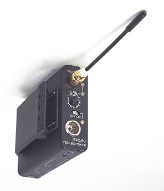
Click to zoom
Application Details
- Equipment Class
- TBC - Licensed Broadcast Station Transmitter
- Date of Grant
- Apr 09, 2001
- Application Purpose
- Original Equipment
- Date of Application
- Apr 09, 2001
- Equipment Note
- Wireless Microphone Transmitter
- Frequency Range
- 470.00000000 - 802.00000000
- Company
- Lectrosonics Inc
- Country
- United States
Documents & Files
Document Text
Text extracted from the exhibit documents filed with the FCC. Open a document above to read the original.
Users Manual
UM 700 DIGITAL FREQUENCY-AGILE UHF BELT-PACK TRANSMITTER LECTROSONICS, INC. Rio Rancho, NM www.lectrosonics.com OPERATING INSTRUCTIONS and trouble-shooting guide 2 TABLE OF CONTENTS The UM200C transmitter is FCC type accepted under Part 74: 470-608MHz and 614-802MHz INTRODUCTION.................................................................................................. 3 GENERAL TECHNICAL DESCRIPTION............................................................ 4 CONTROLS AND FUNCTIONS.......................................................................... 6 BATTERY INSTALLATION................................................................................... 8 OPERATING INSTRUCTIONS............................................................................ 8 OPERATING NOTES........................................................................................... 9 ADJUSTING THE TRANSMITTER FREQUENCY.............................................. 9 MICROPHONE CORD TERMINATION............................................................. 10 5-PIN INPUT JACK WIRING............................................................................. 11 A6U UHF ANTENNA.......................................................................................... 13 TROUBLESHOOTING....................................................................................... 14 SPECIFICATIONS AND FEATURES................................................................. 15 SERVICE AND REPAIR..................................................................................... 16 RETURNING UNITS FOR REPAIR................................................................... 16 WARRANTY......................................................................................... Back cover 3 Frequency Agile UHF Belt-Pack Transmitter Rio Rancho, NM – USA INTRODUCTION The 700 Series wireless system was designed to take advantage of the superior audio performance provided by DSP audio signal processing and the security provided by proprietary digital and encrypted digital radio operation. Several advantages are provided by a digital wireless system and DSP technology: • A digital radio system provides outstanding signal to noise ratio • The signal to noise ratio of a digital radio system does not vary with the RF signal strength arriving at the receiver. • DSP audio signal processing provides a superior limiter • Eavesdropping is difficult and secure encryption techniques can be implemented The UM700 is a rugged, machined aluminum package in a belt-pack configuration with a removable, spring loaded belt clip. A 5-pin input jack provides taps for any microphone or line level signal. The unit is powered by a single 9 Volt alkaline or lithium battery, or from external DC using an optional battery eliminator. The an- tenna is a detachable, locking 1/4 wavelength flexible bronze alloy cable that con- nects to a 50 Ohm SMA port on the control panel. Only the UM700 transmitter is covered in this manual. Companion receivers are covered in separate manuals. The UM700 will operate with any 700 Series Lec- trosonics receiver in the same frequency block. 4 UM700 Block Diagram 5 4 3 2 1 Freq Switches Shunt Limiter From DSP LF Roll-Off Preamp and Supersonic Filter Audio Gain +5V Bias Supply Mic Jack Buffer and Lo Freq Filter Analog to Digital Converter Digital Signal Processor To uP Modulator Drive Amp Power Amp 1 2 3 1/4 Wave Antenna 50 Audio Level Oscillator Filter Synthesizer To uP uP EEProm Multicolor Audio Level LEDs Multicolor Battery Status LED Switching Pwr Supply Delay Control from uP 9V Polarity Protection Diode Power Switch 4V Main Pwr Supply Isolator GENERAL TECHNICAL DESCRIPTION GENERAL The 700 Series wireless system uses digital modulation for an extremely high signal to noise ratio and freedom from distortion and compandor artifacts. The input preamplifier uses an ultra low noise op amp for an excellent signal to noise ratio. A dual-envelope limiter is implemented by the DSP firmware to cleanly limit input signal peaks up to 30dB above full modulation. The transmitter circuits are all regulated to allow full output power from the beginning (9 Volts) to the end (5.5 Volts) of battery life. The UM700 transmitter is comprised of a number of functional sub-systems as shown in the block diagram below. DIGITAL MODULATION Digital modulation is used to eliminate compandor artifacts and provide an extremely high signal to noise ratio. A proprietary compression algorithm is used to contain the RF energy into a narrower bandwidth than other digital systems to allow the 700 Series system to utilize frequencies in FCC Part 74 for broadcast and motion picture production. For applications that require secure operation that prevent eavesdropping, encryption can easily be implemented. AUDIO PROCESSING The input circuitry includes an adjustable low frequency roll-off filter ahead of the limiter and gain stage to customize the low frequency response for varying conditions. In controlled environments with minimal low frequency ambient noise, such as a film production set, the frequency response can be extended to 30 Hz. For applications with excessive low frequency energy, such as in a moving vehicle or rooms with HVAC noise, the low end can be rolled off as high as 150 Hz to reduce the effects of the noise. A “dual-envelope” limiter with 30 dB of range is next in the signal chain. This special limiter is software controlled, being driven by the DSP to minimize “overshoot” and slow attack times that can occur in other types of limiter circuits. The compressor works with two different time constants to cleanly handle a wide variety of dynamics. A fast peak limiter prevents overload distortion from sharp, infrequent transients in the audio signal, and an averaging limiter with longer time constants prevents “pumping” (gain modulation) that can occur with repeated peaks that are closely spaced. Supersonic filtering is provided to prevent exc…
Text truncated - open the document above for the full version.
Cover Letter(s)
April 5, 2001 TIMCO TCB Services acting as agents for the Federal Communications Commission Equipment Approval Services P.O. Box 35815 Pittsburgh, PA 15251-3315 Applicant: LECTROSONICS, INC. 581 Laser Road Rio Rancho, NM 878124 Larry Fisher Vice President of Engineering RE: Confidentiality for schematics Equipment:FCC ID: DBZUM700 FCC Rules:Part 2 and 74 Gentlemen: Lectrosonics Inc. requests that the material in the schematic diagrams be withheld from public disclosure in accordance with Section 0.459 of the Commissions Rules, 47 CFR 0.459, following the grant of certification. In support of this request, Lectrosonics Inc. submits the following: 1. Identification of the specific information for which confidential treatment is sought: The materials set forth in the schematic diagrams which are segregated from the non-confidential exhibits of the application, are those for which confidentiality is sought. 2. Identification of the Commission proceeding in which the information was submitted or a description of the circumstances giving rise to the submission: The proceeding is that involving the application for equipment authorization (certification) under FCC ID number DBZUM700. 3. Explanation of the degree to which the information is commercial or financial, or contains trade secrete or is privileged: This material includes a detailed schematic of the device. As such this material is treated as highly confidential business information. 4. Explanation of the degree to which the information concerns a service that is subject to competition: The material for which confidentiality is ought is employed in the design and manufacture of wireless microphone systems transmitting equipment that is offered on a highly competitive basis. Customers for this equipment have a variety of competing sources. ROGERS LABS, INC. 4405 West 259 th Terrace Louisburg, KS 66053 Phone / Fax (913) 837-3214 l Page 2April 5, 2001 5. Explanation of how disclosure of this information could result in substantial competitive harm: Disclosure would, in effect, give away the fruits of the labors of Lectrosonics Inc.’s engineering department and personnel, who have designed the equipment and manufacturing process. Disclosure would also offer competitors additional unwarranted insight into the state of the product development, thereby allowing competitors an advantage, not available to Lectrosonics Inc. 6. Identification of any measures taken by the submitting party to prevent unauthorized disclosure: The information for which confidential treatment is ought is kept confidential by Lectrosonics Inc. and not made available to third parties except pursuant to non-disclosure agreements. 7. Identification of whether the information is available to the public and the extent of any previous disclosure of the information to third parties: To the knowledge of those preparing this application, the information has not been disclosed publicly heretofore. While the general theory of operation of this equipment has been the subject of numerous disclosures in industry and standards groups as well as in the rule making proceedings of the FCC, the protection sought is narrowly drawn and pertains to certain specific implementations of the digital modulation technology. 8. Justification of the period during which the submitting party asserts that the material should not be available for public disclosure: This material should not be disclosed for at least 25 years. While improvements in the design are made relatively frequently, disclosure of the design information would lead to insights into both design and manufacturing techniques that could have an adverse competitive effect for many years to come. Thus, equipment is designed for commercial, industrial and governmental applications. As such, unlike most consumer equipment, this equipment will be used for more than a decade in some cases. As such, it is important that the design not be made available to unauthorized persons who might attempt to use knowledge of the design to compromise the applications for which the equipment will be employed. 9. Any other information that the party seeking confidential treatment believes may be useful in assessing whether its request for confidentiality should be granted: See item 8 above. Note that the equipment for which approval is being sought will be employed in applications that inherently place a premium on security. The special fee for request of confidentiality will be submitted with the application. Should you require any further information, please contact the undersigned. Thank you for your consideration in this matter. Sincerely, Scot Rogers Rogers Labs, Inc. Enclosures
External Photos
External Photographs
ID Label/Location Info
UM700 serial number PRODUCTION ARTWORK M. Fowler 3/21/01 LF ROLL OFF 35150 75 Hz FCCID:DBZUM700 Lectrosonics, Inc. Made in U.S.A. SN: xxxx
Internal Photos
Internal Photographs of Device under test. Assymbley top Audio Printed Circuit board bottom. Audio Printed Circuit board top. Transmitter Printed Circuit board bottom. Transmitter Printed Circuit board top.
Operational Description
2.1033, Item 10 UM700 Frequency Stabilization, Power and Spurious Limiting The UM700 is a frequency synthesized transmitter. The frequency is referenced to a 4 MHz crystal, PCB # 17293, XT1. XT1 is a high accuracy temperature stable crystal. The synthesizer IC, PCB # 17292, U4 provides a lock detect signal. The microprocessor( PCB # 17293, U8 continuously monitors the status of the lock detect signal. In the event of the synthesizer going unlocked, the microprocessor shuts down the RF power by disabling the I/Q modulator( PCB # 17292, U3) via the RF_MUTE signal. Emissions that are close in frequency to the carrier are attenuated by 5 pole bessel filters( PCB # 17292, U13, U2, U12) that filter the I/Q voltages that are applied to the quadrature modulator( U3). These bessel filters, in addition to the nominal 240 Kbps data rate, limit the occupied bandwidth to less than 180 KHz. The nominal 3 dB cut-off frequency for the bessel filters is set to 55 KHz. Since the carrier frequency is generated via a frequency doubler, RF emissions exist at one half the carrier frequency. These emissions are suppressed in the VCO( PCB # 17298) by two frequency doublers( U14( Q2), and Q1) tuned to the RF carrier frequency. Harmonics of the carrier are generated in the final RF power amplifier( PCB # 17292, U1). This stage is operated at 1 dB below its 1 dB compression point. L5, and C15 provide attenuation of harmonics. The isolator, ISO1, also provides attenuation of spurious emissions. In addition, a diplexing network consisting of C10, L16, C1, L17, and R16 provides a very broadband match for U1, further attenuating higher frequency harmonics( greater than 1.5 GHz) and stabilizing U1.
Parts List/Tune Up Info
2.1033, Item 9 UM700 Tune Up Procedure Equipment Required RF Spectrum Analyzer with sensitivity of –100 dBm or better, frequency range of 10 MHz to 3 GHz or wider, 50 ohms, capable of +25 dBm without overload or distortion. Capable of measuring occupied bandwidth. Used in development: HP-E4405B Frequency Counter covering 10 MHz to 806 MHz with an accuracy of +/- 100 Hz and readout to 10 Hz or better. This function may be resident in higher end spectrum analyzers. Used in Development: Tektronix CMC251 Digital Multimeter capable of measuring current to at least 200 mA and voltage to 10 VDC with an accuracy of 3% or better. Used in development: Fluke Model 87 Power Supply for bench top use capable of supplying 9.0 VDC at 200 mA . Both current and voltage should be metered. Used in development: Leader LPS 152A RF Power Meter, 50 Ohm, capable of measuring RF power to 806 MHz at power levels to +20 dBm at an accuracy of 5%. Used in development: Agilent E4418B with HP 8482H power sensor. Audio Analyzer capable of output signal level of +10dBu and distortion measurement less than 1% THD+N. Used in development: Audio Precision A75-1 Test Accessories Audio cable with XLR 3 pin audio connector on one end with pin 1 grounded and pin 3 as audio. The other end should be BNC male. 50 Ohm coaxial cable 2 to 3 feet long is necessary for connecting the RF output of the UM700 to the spectrum analyzer. One end is SMA male, the other is appropriate for spectrum analyzer. There will be approximately 1 dB of loss in this cable at UHF frequencies. All power measurements should correct this loss. Metallic tweezers( electrically conductive) required for putting the transmitter in test mode. Note that this adjustment is performed with the PCBs removed from the housing and is accessible only to Lectrosonics personnel. Check Power Indicator, on/off Status Substitute the power supply for the battery. The supply should current limit at 150 mA. Set the supply for 9.0VDC and turn on the UM700. The current drain should be less than 80 mA on a fully aligned unit. The Red battery indicator on the front panel should be illuminated. Verify that the power led remains illuminated when the DC power is adjusted to +5.0V VDC. Monitor the RF output on the spectrum analyzer with the following settings: Center Frequency to RF carrier Span set to 200 KHz per horizontal division Resolution Bandwidth set to 10 KHz Video Bandwidth set to 10 KHz Verify that there is delay of about 1 second when cycling the power switch from off to on before RF appears. Verify that there is delay of about 1.5 second when cycling the power switch from on to off before RF switches off. This completes the Power indicator test. Preparation Except where noted, all adjustments are performed on the PCB # 17293. Adjustments are to be performed with the power supply set to +9.0VDC and current limit set to 150 mA. All measurements are referenced to the RF-cold PC ground plane. The PCB # 17292 and 17293 should be mated together with the front panel attached. Preset Adjustments There are two hexadecimal switches on the PCB. The left switch, SW2, sets the RF carrier frequency in 1.6 MHz steps. The right switch, SW1, sets the frequency in 100 KHz steps. The notation used here will be ( # #) or ( SW2 SW1) or steps of ( 1.6 MHz 100 KHz). For example, (A 7) means set SW2 at A and SW1 at 7. Audio Alignment Set Audio Limit Level Using the Audio analyzer, apply a +10 dBu, 1 KHz tone to the audio input of the UM700. Monitor the output at TP2. Set THD+N for less than 1% by adjusting R42. This completes the audio alignment. RF Alignment RF Synthesizer Locking Voltage Adjust the frequency to ( 0 0) and measure the DC voltage at J6-1. Repeat with frequency set to ( F F). Verify that the lock voltages lie between 0.8 VDC and 2.5 VDC for the lower and upper limit of the RF frequency range, respectively. Fine Tune Carrier Suppression Set frequency to ( 7 F), which is about the mid-band of the transmitter. Monitor the signal on the spectrum analyzer using the following setting: Center frequency to RF carrier Span set to 200 KHz per horizontal division Resolution Bandwidth set to 10 KHz Video Bandwidth set to 10 KHz Reference level set to +20 dBm Using tweezers, short pins 1 and 7 on J7. Maintain shorted condition for remainder of fine adjustment. Set SW2 SW1 to ( 0 0). This puts the UM700 in the single sideband test mode. Carrier suppression is achieved by iteratively adjusting the DC offset voltages that are applied to the modulator. a. With SW2 set to 0, adjusting SW1 adds an offset voltage to the I channel. Adjust for best carrier suppression. b. Set SW2 to 1. Adjusting SW1 now adds an offset voltage to the Q channel. Adjust for best carrier suppression. Repeat a and b above until best carrier suppression is achieved. Final carrier suppression should be better that 25 dB( carrier is 25 dB below sideband). Remove tweezers when complete. DC offset values are stored in EEPROM. Fine Tune Carrier Frequency Set frequency to ( 7 F) and monitor the transmitter RF output on the frequency counter. Using tweezers, short pins 1 and 7 on J7. Maintain shorted condition for remainder of adjustment. Set SW2 SW1 to ( F 0). This puts the UM700 in the frequency adjust mode. a. With SW2 set to F, adjusting SW1 offsets the carries frequency. Adjust SW1 such that the RF carrier frequency is within 1 KHz of the desired frequency Remove the tweezers when complete. Fine tune adjustment is stored in EEPROM Occupied Bandwidth Set the frequency to ( 7 F) and monitor the transmitter RF output on the spectrum analyzer. Apply a 1 KHz, +10 dBu tone to the audio input of the UM700. Set the spectrum analyzer to measure occupied bandwidth using the following settings: Span set to 1 MHz Resolution Bandwidth set to 10 KHz Video Bandwidth set to 10 KHz Verify that the occupied bandwidth, 99%, is less than 180 KHz ( 175 KHz nominal). Repeat for frequency settings of ( 0 0) and ( F F). Spurious Emissions Set the frequen…
Text truncated - open the document above for the full version.
Test Report
TEST REPORT For APPLICATION of CERTIFICATION for LECTROSONICS, INC. 581 Laser Road Rio Rancho, NM 878124 Larry Fisher Vice President of Engineering MODEL: UM700 NAME: Wireless Microphone Transmitter FREQUENCY: 470 - 802 MHz FCC ID: DBZUM700 Test Date: March 6, 2001 Certifying Engineer: Scot D. Rogers ROGERS LABS, INC. 4405 West 259 TH Terr. Louisburg, KS 66053 PHONE: (913) 837-3214 FAX: (913) 837-3214 This report shall not be reproduced except in full, without the written approval of the laboratory. This report must not be used by the client to claim product endorsement by NVLAP or any agency of the U.S. Government. ROGERS LABS, INC. 4405 West 259 th Terrace Louisburg, KS 66053 Phone / Fax (913) 837-3214 NVLAP Accredited LaboratoryNVLAP Lab Code: 200087-0 ROGERS LABS, INC.Lectrosonics, Inc. 4405 West 259 TH TerraceMODEL: UM700 Louisburg, KS 66053Test #: 010305 Phone/Fax: (913) 837-3214Test to: FCC Parts 2 & 74Page 2 of 25 LectrosonicsUM700.DOC 03/20/2001 TABLE OF CONTENTS E X H I B I T I:3 FORWARD:3 LIST OF TEST EQUIPMENT3 2.1033 Application for Certification:4 2.1046RF POWER OUTPUT6 Measurements Required:6 Test Arrangement:6 Results:7 2.1047MODULATION CHARACTERISTICS9 Measurements Required:9 Test Arrangement:9 Results:10 2.1049OCCUPIED BANDWIDTH10 Measurements Required:10 Test Arrangement:10 Results:11 2.1051 SPURIOUS EMISSIONS AT ANTENNA TERMINALS11 Measurements Required:11 Test Arrangement:12 Results:13 2.1053FIELD STRENGTH OF SPURIOUS RADIATION14 Measurements Required:14 Test Arrangement:14 Results:15 2.1055FREQUENCY STABILITY18 Measurements Required:18 Test Arrangement:19 Results:20 E X H I B I T II:21 APPENDIX21 NVLAP Accredited LaboratoryNVLAP Lab Code: 200087-0 ROGERS LABS, INC.Lectrosonics, Inc. 4405 West 259 TH TerraceMODEL: UM700 Louisburg, KS 66053Test #: 010305 Phone/Fax: (913) 837-3214Test to: FCC Parts 2 & 74Page 3 of 25 LectrosonicsUM700.DOC 03/20/2001 E X H I B I T I: FORWARD: In accordance with the Federal Communications Code of Federal Regulations, dated October 1, 1999, Part 2 Subpart J, Paragraphs 2.907, 2.911 to 2.913, 2.925, 2.926, 2.1031 through 2.1057 and; Part 74 Subpart H; Paragraphs 74.801 through 74.861 the following is submitted: List of Test Equipment A Hewlett Packard 8591EM and or 8562A Spectrum Analyzer was used as the measuring device for the emissions testing. The analyzer settings used are described in the following table. Refer to the Appendix for a complete list of Test Equipment. HP 8591EM SPECTRUM ANALYZER SETTINGS CONDUCTED EMISSIONS: RBWAVG. BW DETECTOR FUNCTION 9 kHz30 kHzPeak/Quasi Peak RADIATED EMISSIONS (30 – 1000 MHz): RBWAVG. BW DETECTOR FUNCTION 120 kHz300 kHzPeak/Quasi Peak HP 8562A SPECTRUM ANALYZER SETTINGS RADIATED EMISSIONS (1 – 40 GHz): RBWAVG. BW DETECTOR FUNCTION 1 MHz1 MHzPeak/Average ANTENNA CONDUCTED EMISSIONS: RBWAVG. BW DETECTOR FUNCTION 100 kHz300 kHzPeak NVLAP Accredited LaboratoryNVLAP Lab Code: 200087-0 ROGERS LABS, INC.Lectrosonics, Inc. 4405 West 259 TH TerraceMODEL: UM700 Louisburg, KS 66053Test #: 010305 Phone/Fax: (913) 837-3214Test to: FCC Parts 2 & 74Page 4 of 25 LectrosonicsUM700.DOC 03/20/2001 2.1033 Application for Certification: (c)Applications for equipment other than that operating under Parts 15 and 18 of the rules shall be accompanied by a technical report containing the following information: (1) The full name and mailing address of the manufacturer of the device and the applicant for certification. Lectrosonics, Inc. 581 Laser Road Rio Rancho, NM 87124 (2)FCC identifier.DBZUM700 (3)A copy of the installation and operating instructions to be furnished the user. A draft copy of the instructions may be submitted if the actual document is not available. The actual document shall be furnished to the FCC when it becomes available. Refer to the instruction manual furnished with this application for details. (4)Type or types of emission.180K Q2E (5)Frequency range. 470 to 806 MHz with lockout provisions on restricted frequency bands. (6)Range of operating power values or specific operating power levels, and description of any means provided for variation of operating power. The output power is factory set to 50 mW (nominal). The EUT has no provision for operator variation of the output power. (7)Maximum power rating as defined in the applicable part(s) of the rules. As stated in CFR 47, 74.861(e)(ii), the maximum permissible output power allowed is 250 mW. (8)The dc voltages applied to and dc currents into the several elements of the final radio frequency amplifying device for normal operation over the power range. The EUT final amplification stage runs at 4 volts with 42 mA current for a power requirement of 168 mW. (9) Tune-up procedure over the power range, or at specific operating power levels. Refer to the tune-up procedure furnished with this application for details. (10) A schematic diagram and a description of all circuitry and devices provided for determining and stabilizing frequency, for suppression of spurious radiation, for limiting NVLAP Accredited LaboratoryNVLAP Lab Code: 200087-0 ROGERS LABS, INC.Lectrosonics, Inc. 4405 West 259 TH TerraceMODEL: UM700 Louisburg, KS 66053Test #: 010305 Phone/Fax: (913) 837-3214Test to: FCC Parts 2 & 74Page 5 of 25 LectrosonicsUM700.DOC 03/20/2001 modulation, and for limiting power. Refer to the schematics furnished with this application for details. (11)A photograph or drawing of the equipment identification plate or label shows the information to be placed thereon. Refer to the FCC identification label furnished with this application for details. (12)Photographs (8'' x 10'') of the equipment of sufficient clarity to reveal equipment construction and layout, including meters, if any, and labels for controls and meters and sufficient views of the internal construction to define component placement and chassis assembly. Insofar as these requirements are met by photographs or drawings contained in instruction manuals supplied with the certification request, additiona…
Text truncated - open the document above for the full version.
Contact Information
Applicant
Robert Cunnings(Vice President, Engineering)
Test Firm
Rogers Labs, Inc.Scot Rogers
Technical Specifications
| # | Rule Parts | Frequency Range | Power Output | Emission | Tolerance |
|---|---|---|---|---|---|
| 1 | 74 | 470 MHz - 802 MHz | 50.00 mW | 180KQ2E | 0.0010000000 % |
Other Applications from Lectrosonics Inc
DBZT20A
Jun 05, 2026Digital Hybrid Wireless microphone transmitter
Equipment Class
TLD - Licensed LPAS DeviceDBZT20B
Jun 05, 2026Digital Hybrid Wireless microphone transmitter
Equipment Class
TLD - Licensed LPAS DeviceDBZDCHTB
Sep 08, 2024Digital Camera Hop Transmitter
Equipment Class
DWM - Part 15 Wireless Microphone
DBZDBSMA
Jan 25, 2021Digital Wireless Microphone Transmitter
Equipment Class
TLD - Licensed LPAS Device
DBZSMWB79
Jul 20, 2020Body-worn Wireless Microphone Transmitters
Equipment Class
TLD - Licensed LPAS Device