DBZWMMWireless Microphone Transmitter
Lectrosonics Inc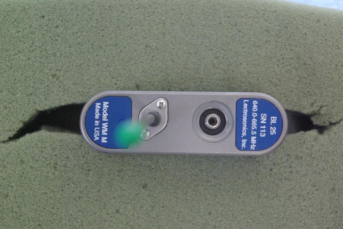
Click to zoom
Application Details
- Equipment Class
- TBT - Licensed Broadcast Transmitter Worn on Body
- Date of Grant
- Jun 07, 2012
- Application Purpose
- Original Equipment
- Date of Application
- Jun 07, 2012
- Equipment Note
- Wireless Microphone Transmitter
- Frequency Range
- 614.40000000 - 691.10000000
- Company
- Lectrosonics Inc
- Country
- United States
Documents & Files
Document Text
Text extracted from the exhibit documents filed with the FCC. Open a document above to read the original.
Users Manual
WM Watertight Transmitter and Remote Controls With Digital Hybrid Wireless ® Technology INSTRUCTION MANUAL Rio Rancho, NM, USA www.lectrosonics.com Fill in for your records: Serial Number: Purchase Date: US Patent 7,225,135 WM LECTROSONICS, INC. 2 Watertight Transmitter Rio Rancho, NM 3 Introduction The WM transmitter is designed to resist damage when used in wet or dusty conditions and also offer a compre- hensive feature set that makes it equally at home in film and television production and on stage. A solid machined aluminum housing with a corrosion re- sistant finish hosts dual battery compartments, a mois- ture sealed control panel with backlit LCD and enlarged membrane switches. Recessed seats for the O-rings in the battery caps and input jack allow the caps and mic connector to be tightened securely without excessive deformation of the O-rings. The antenna is made of an extremely durable, multi- strand alloy that will withstand heavy abuse. It is mount- ed with a compression sealed strain relief that prevents dust and moisture from entering the housing. As the first stage in the signal processing chain, the input preamp section includes very high quality, low noise components with a wide range of gain adjust- ment in 1 dB increments and a DSP-controlled input limiter. Dual color LEDs on the control panel accurately indicate audio input level for precise gain adjustment. Easily accessed screens on the LCD simplify setup and adjustments. Output power is adjustable to provide either extended operating range or extended battery life as needed for the application. The Digital Hybrid Wireless ® design (US Patent 7,225,135) combines 24-bit digital audio with analog FM resulting in a system that has the same operating range as analog systems, the same spectral efficiency as analog systems, the same long battery life as analog systems, plus the excellent audio fidelity typical of pure digital systems. The DSP-based design works with all Digital Hybrid receivers, and is backward compatible for use with Lectrosonics 200 Series, 100 Series, IFB receivers and some other brands of analog wireless receivers. Consumer Alert for US Users - FCC Order DA 10-92 Most users do not need a license to operate this wireless microphone system. Nevertheless, operating this micro- phone system without a license is subject to certain restrictions: the system may not cause harmful interference; it must operate at a low power level (not in excess of 50 milliwatts); and it has no protection from interference received from any other device. Purchasers should also be aware that the FCC is currently evaluating use of wireless mi- crophone systems, and these rules are subject to change. For more information, call the FCC at 1-888- CALL-FCC (TTY: 1-888-TELL-FCC) or visit the FCC’s wireless microphone website at www.fcc.gov/cgb/wirelessmicrophones. To operate wireless microphone systems at power greater than 50mW, you must qualify as a Part 74 user and be licensed. If you qualify and wish to apply for a license go to: http://www.fcc.gov/Forms/Form601/601.html Table of Contents Introduction ...........................................................................3 General Technical Description ............................................4 Servo Bias Input..................................................................4 No Pre-Emphasis/De-Emphasis .........................................4 Low Frequency Roll-Off ......................................................4 Input Limiter ........................................................................4 Signal Encoding and Pilot Tone ..........................................5 Microprocessor Control .......................................................5 Compatibility Modes ............................................................5 Control Panel ......................................................................5 Wide-Band Deviation ..........................................................5 Variable Power Output ........................................................5 Battery Operation ................................................................5 Frequency Blocks ................................................................5 Circulator/Isolator ................................................................5 Controls and Functions .......................................................6 LCD Screen ........................................................................6 Power LED ..........................................................................6 Audio Input Jack ..................................................................6 Battery Compartment and Thumb Screw ............................6 Modulation LEDs .................................................................6 AUDIO Button .....................................................................6 FREQ Button .......................................................................6 Up/Down Arrows .................................................................6 Antenna ...............................................................................6 About Batteries .....................................................................7 Battery Compartments .........................................................7 Attaching and Removing the Microphone ..........................7 Operating Instructions .........................................................8 Power Up and Boot Sequence ............................................8 Power Down ........................................................................8 Standby Mode .....................................................................8 Compatibility, Output Power, Bias Voltage (phantom power) and LCD Backlight ..............................................................8 Audio LF Roll-off and Gain ..................................................9 Frequency Selection ....................................................…
Text truncated - open the document above for the full version.
Cover Letter(s)
April 16, 2012 Timco Engineering Inc. Federal Communications Commission 849 NW State Road 45 Equipment Approval Services Newberry, FL 32669 Applicant: Lectrosonics, Inc. 581 Laser Road Rio Rancho, NM 87124 Re: Confidentiality for submittal information regarding FCC ID number DBZWMM PRODUCT: Wireless Microphone transmitter operating under part 74H Dear Sirs: Lectrosonics, Inc. requests that the material in the Parts List, Schematics, Block Diagram, and Operational Description be withheld from public disclosure pursuant to Sections 0.457 and 0.459 of the Commission’s Rules following grant of the application. In support of this request, Lectrosonics, Inc. submits the following. Permanent Confidential files Block Diagram Conf BlkDia WMM.pdf Parts List Conf PartList WMM.pdf Operational Description Conf OpDes WMM.pdf Schematics Conf Schem WMM1.pdf Schematics Conf Schem WMM2.pdf 1. Identification of the specific information for which confidential treatment is sought: The materials set fourth in the Operational Description, Parts List, block diagram, and Schematics, which are segregated from the non-confidential exhibits of the application, are those for which confidentiality is sought. 2. Identification of the Commission proceeding in which the information was submitted or a description of the circumstances giving rise to the submission: The proceeding is that involving the application for equipment authorization (certification) under FCC ID: DBZWMM 3. Explanation of the degree to which the information is commercial or financial, or contains a trade secret or is privileged: This material includes a detailed theory of operation, circuit diagrams, (schematic diagrams) and detail Parts List. As such, this material is treated as highly confidential business information. ROGERS LABS, INC. 4405 West 259 th Terrace Louisburg, KS 66053 (913) 837-3214 4. Explanation of the degree to which the information concerns a service that is subject to competition: The material for which confidentiality is sought is employed in the design and manufacture of this transmitting equipment that is offered on a highly competitive basis. Customers for this equipment have a variety of competing sources. 5. Explanation of how disclosure of the information could result in substantial competitive harm: Disclosure would, in effect, give away the fruits of the labors of Lectrosonics, Inc.’s engineering personnel, who have designed the equipment and the manufacturing process. Disclosure would also offer competitors additional unwarranted insight into the state of the product development, thereby allowing competitors an advantage, not available to Lectrosonics, Inc. 6. Identification of any measures taken by the submitting party to prevent unauthorized disclosure: The information for which confidential treatment is sought is kept confidential by Lectrosonics, Inc. and not made available to third parties except pursuant to non-disclosure agreements. 7. Identification of whether the information is available to the public and the extent of any previous disclosure of the information to third parties: To the knowledge of those preparing this application, the information has not been disclosed publicly heretofore. While the general theory of operation of this equipment has been the subject of numerous disclosures in industry and standards groups as well as in rule making proceedings of the FCC, the protection sought is narrowly drawn and pertains to certain specific implementations of this radio technology. 8. Justification of the period during which the submitting party asserts that the material should not be available for public disclosure: This material should not be disclosed for at least 25 years. While improvements in design are made relatively frequently, disclosure of the design information would lead to insights into both design and manufacturing techniques that could have an adverse competitive effect for many years to come. This equipment is designed for commercial, industrial, and governmental applications. As such, unlike most consumer equipment, this equipment could be used for more than a decade in some cases. As such, it is important that the design not be made available to unauthorized persons who might attempt to use knowledge of the design to compromise the applications for which the equipment will be employed. Should you require any further information, please contact the undersigned. Thank you for your consideration in this matter. Sincerely, Scot Rogers
Cover Letter(s)
April 11, 2008 Federal Communications Commission Equipment Approval Services Post Office Box 358315 Pittsburgh, Pennsylvania 15215-5315 To Whom It May Concern: Please be advised that Lectrosonics. Inc. has authorized Scot Rogers of Rogers Labs. Inc. to act on behalf in all matters relating to application for equipment authorization, including the signing of all documents relating to these matters and submittals. All acts carried out by Rogers Labs. Inc. on our behalf shall have the same effects as our own. Rogers Labs, Inc. is authorized to receive and exchange data between our company and the Commission. This Authorization is made pursuant to Paragraph 2.911 of FCC Rules CFR47. This Authorization is in effect until otherwise notified in writing. President Lectrosonics, Inc.
Cover Letter(s)
July 3, 2012 Timco Engineering Inc. 849 NW State Road 45 Newberry, FL 32669 Applicant: Lectrosonics, Inc. 581 Laser Road Rio Rancho, NM 87124 Re: Label Sample revision for FCC ID: DBZWMM Gentlemen Please accept this revised label sample for use in replacing the original exhibit submitted with application. It was brought to our attention the label did not comply with CFR47 2.1925 identification of equipment requirements. The label has been corrected by placing the letters “ID” in the FCC ID test line. No product has been distributed and all produced products have been correctly labeled using the corrected labeling. Please process this information to the FCC for replacement of incorrect label sample exhibit originally submitted. Should you require any further information, please contact the undersigned. Thank you for your consideration in this matter. Sincerely, Scot Rogers Rogers Labs, Inc. Enclosures ROGERS LABS, INC. 4405 West 259 th Terrace Louisburg, KS 66053 Phone / Fax (913) 837-3214
External Photos
Rogers Labs, Inc. Lectrosonics, Inc. IC: 8024A-WME 4405 West 259 TH Terrace Model: WME FCC ID: DBZWME Louisburg, KS 66053 Test #: 120312E SN: 118, 101, 103 Phone/Fax: (913) 837-3214 Test to: CFR47 Parts 2 & 74H, RSS-123, Issue 2 Date: April 16, 2012 Revision 1 File: ExtPho WME Page 1 of 2 External photographs of equipment under test Rogers Labs, Inc. Lectrosonics, Inc. IC: 8024A-WME 4405 West 259 TH Terrace Model: WME FCC ID: DBZWME Louisburg, KS 66053 Test #: 120312E SN: 118, 101, 103 Phone/Fax: (913) 837-3214 Test to: CFR47 Parts 2 & 74H, RSS-123, Issue 2 Date: April 16, 2012 Revision 1 File: ExtPho WME Page 2 of 2
ID Label/Location Info
Rogers Labs, Inc. Lectrosonics, Inc. IC: 8024A-WMM 4405 West 259 TH Terrace Model: WMM FCC ID: DBZWMM Louisburg, KS 66053 Test #: 120312M SN: 111, 113, 115 Phone/Fax: (913) 837-3214 Test to: CFR47 Parts 2 & 74H, RSS-123, Issue 2 Date: April 16, 2012 Revision 1 File: LabelSmp WMM Page 1 of 1 Label Sample and Placement Label Placement Label Placement
ID Label/Location Info
Rogers Labs, Inc. Lectrosonics, Inc. IC: 8024A-WMM 4405 West 259 TH Terrace Model: WMM FCC ID: DBZWMM Louisburg, KS 66053 Test #: 120312M SN: 111, 113, 115 Phone/Fax: (913) 837-3214 Test to: CFR47 Parts 2 & 74H, RSS-123, Issue 2 Date: July 3, 2012 Revision 2 File: LabelSmp WMM r2 Page 1 of 1 Label Sample and Placement Label Placement Label Placement
Internal Photos
Rogers Labs, Inc. Lectrosonics, Inc. IC: 8024A-WMM 4405 West 259 TH Terrace Model: WMM FCC ID: DBZWMM Louisburg, KS 66053 Test #: 120312M SN: 111, 113, 115 Phone/Fax: (913) 837-3214 Test to: CFR47 Parts 2 & 74H, RSS-123, Issue 2 Date: April 16, 2012 Revision 1 File: IntPho WMM Page 1 of 2 Internal Photographs RF PCB Front without shields RF PCB Back Rogers Labs, Inc. Lectrosonics, Inc. IC: 8024A-WMM 4405 West 259 TH Terrace Model: WMM FCC ID: DBZWMM Louisburg, KS 66053 Test #: 120312M SN: 111, 113, 115 Phone/Fax: (913) 837-3214 Test to: CFR47 Parts 2 & 74H, RSS-123, Issue 2 Date: April 16, 2012 Revision 1 File: IntPho WMM Page 2 of 2 Digital PCB Back Digital PCB Front
Parts List/Tune Up Info
Lectrosonics Standard Test & Alignment Procedure Part number(s):WMHardware version(s):17419B (radio) & 17420B (audio)Firmware version(s):2.0 Part number(s):WM/E01Hardware version(s):17419B (radio) & 17420B (audio)Firmware version(s):2.0 Part number(s):WM/E02Hardware version(s):17419B (radio) & 17420B (audio)Firmware version(s):2.0 Common name:WM transmittersAuthor(s):Cruz Garcia & Rodney WildhagenTest procedure version:01.00 Date:09 Apr 2012 Test segment #10 of 40 NOTE: This need only be performed it is powered up, when μC IC is replaced, or when a firmware update is desired and confirmed to be appropriate. Only audio boards are required for this segment. Initial setup: Audio board with PIC18F67J11 μC IC Step Measurement name & descriptionMeasurement result (Typ) 10.10 Program μC IC and measure audio board current draw 10.10.10+3.3 VDC, 200 mA current limit in at audio board J8-10 (J8-1 is circuit common) 10.10.20Measure current draw(?) 10.10.30Program μC IC via ICSP port (J6) 10.10.40Remove ICSP cable from DUT 10.10.50Measure current draw(76) Note The goal here is to be sure the audio board is powered up, the μC IC is running, and the audio board is not burning up with fever. A tighter tolerance current draw measurement will be made later 10.10.60Remove DC power from audio board Test segment #20 of 40 NOTE: This segment may be performed using one audio board to test multiple radio boards Initial setup: Known good, pre-tested audio board connected to the radio board. Test key pad connected to audio board J3. All voltage measurements referenced to DUT circuit common All audio signal amplitude measurements taken with a <10 Hz HPF and 80 kHz LPF (use filter on audio signal analyzer, not modulation meter) All audio signal noise and distortion measurements taken with a 22Hz HPF and 22kHz LPF (use filter on audio signal analyzer, not on modulation meter) All demodulated carrier and carrier deviation measurements taken with a Hewlett Packard 8901A modulation analyzer with no 8901A filters selected. Use of other instruments may yield different results particularly measurements pertaining to noise and phase and measurements where noise is a significant factor This font indicates use the Alternate Method to manual testing using the LectroLink apparatus and LecNet2 Command Terminal Utility. Sub-steps bearing the same number indicate alternate method(s). Use of the LectroLink apparatus creates an additional opportunity for ground loop currents which commonly disrupt LectroLink communications so use of an optically isolated USB hub (B and B Electronics model UISOHUB4 or equivalent) is recommended. The LectroLink method is the only method to adjust carier power, no menu equivalent exists. StepMeasurement name & descriptionMeasurement result (Typ) 20.10 Audio board frequency block assignment 20.10.10+1.5 VDC, 2.5 A current limit in at radio board P4-1 (P7-1 is circuit common). 20.10.20.10 Hold Audio and Frequency buttons simultaneously on test panel key pad for 3 seconds while shorting audio board TP5 (TEST) to J6-4 (circuit common). This powers DUT up in factory mode. 20.10.20.20Press test panel keypad AUD switch repeatedly until LCD displays frequency block number 20.10.20.30Press test panel keypad UP or DOWN switch repeatedly to assign appropriate block number 20.10.20.10 block= (acceptable values are 470, 19-33, 944, 400-999) 20.10.20.20 Cycle DUT power Lectrosonics Standard Test & Alignment Procedurefile:///S:/product_data/TEST/standard_test/wm__test_hw17419b_17420... 1 of 104/13/2012 11:07 AM 20.20Power supply voltage measurements Note On 06 Mar 2012 I requested of Dave Bundy that the next board rev set contain test points for all supply rail voltages not available at a header. 20.20.+3.3VMeasure DC voltage at audio board:J8-10 (+3.3V) +3.135 to +3.465VDC (+3.3) 20.20.BAT+J8-12 (BAT+) +1.485 to +1.515VDC (+1.5) 20.20.+6VJ8-13 (+6V)+5.65 to +6.25VDC (+5.95) 20.20.-3VJ8-14 (-3V)-2.73 to -2.47VDC(-2.6) 20.20.+6V_SLEEPJ2-4 (+6V_SLEEP)+5.65 to +6.25VDC (+5.95) 20.20.-3V_SLEEPJ2-3 (-3V_SLEEP)-2.73 to -2.47VDC(-2.6) 20.20.+3.3V_SLEEPJ2-2 (+3.3V_SLEEP) +3.135 to +3.465VDC (+3.3) 20.20.+3VMeasure DC voltage at radio board:C48, U6 jct (+3V)(?) 20.20.+4V_VARTP3 (+4V_VAR)+2.82 to +3.15VDC (+3) 20.30 VCO adjustment & VCO start-up test 20.30.10 Install VCO shield tuning cover. If possible it should make good electrical connection to the resonator and the shield fence. DO NOT SOLDER IT IN PLACE! 20.30.20Navigate menu so LCD reads Aud 20.30.30Press test panel key pad FREQ button twice, LCD reads "CH--" 20.30.40Press test panel key pad FREQ and UP or DWN button to select highest carrier frequency 20.30.50 channel= assign highest carrier freq. 20.30.60Adjust radio board C23 for 2.5 VDC at radio board TP1 (VCO_CONT)+2.45 to +2.55 VDC (+2.5) 20.30.70Remove DC power from DUT 20.30.80Wait 3 sec. 20.30.90Restore DC power to DUT 20.30.100 Measure DC voltage at radio board TP1 (VCO_CONT) as an indicator that the VCO starts on power up at selected carrier frequency +2.45 to +2.55 VDC (+2.5) 20.30.110Press test panel key pad FREQ and UP or DWN button to select lowest carrier frequency 20.30.110 channel= assign lowest carrier freq. 20.30.120Measure DC voltage at radio board TP1 (VCO_CONT)+0.6 to +1.2 VDC 20.30.130Remove DC power from DUT 20.30.140Wait 3 sec. 20.30.150Restore DC power to DUT 20.30.160 Measure DC voltage at radio board TP1 (VCO_CONT) as an indicator that the VCO starts on power up at selected carrier frequency +0.6 to +1.2 VDC 20.40 Carrier signal power adjustments & spectral purity measurements Note If the LectroLink tool is used to perform all DUT manupulations, it is not necessary for the DUT to be in Factory mode to perform this step. 20.40.10Press test panel keypad AUD switch until LCD displays P__XXX (carrier power menu, 250mW, lowest carrier freq.) Note This sets the DUT to 250mW carrier power at the lowest carrier frequency, from here pressing the FREQ switch once will move to the middle carrier freq.…
Text truncated - open the document above for the full version.
RF Exposure Info
© 2012 RF Exposure Lab, LLC This report shall not be reproduced except in full without the written approval of RF Exposure Lab, LLC. 802 N. Twin Oaks Valley Road, Suite 105 • San Marcos, CA 92069 • U.S.A. TEL (760) 471-2100 • FAX (760) 471-2121 http://www.rfexposurelab.com CERTIFICATE OF COMPLIANCE SAR EVALUATION Lectrosonic, Inc. Dates of Test: June 4-5, 2012 581 Laser Road NE Test Report Number: SAR.20120607 Rio Rancho, NM 87124 This wireless mobile and/or portable device has been shown to be compliant for localized specific absorption rate (SAR) for controlled environment limits specified in ANSI/IEEE Std. C95.1-1992 and had been tested in accordance with the measurement procedures specified in IEEE 1528-2003, OET Bulletin 65 Supp. C, KDB447498, RSS-102 and Safety Code 6 (See test report). I attest to the accuracy of the data. All measurements were performed by myself or were made under my supervision and are correct to the best of my knowledge and belief. I assume full responsibility for the completeness of these measurements and vouch for the qualifications of all persons taking them. RF Exposure Lab, LLC certifies that no party to this application is subject to a denial of Federal benefits that includes FCC benefits pursuant to Section 5301 of the Anti-Drug Abuse Act of 1988, 21 U.S.C. 853(a). Jay M. Moulton Vice President Certificate # 2387.01 FCC ID: DBZWMM IC Certificate: 8024A-WMM Model(s): WM M Test Sample: Engineering Unit Same as Production Serial No.: Various (See Data Sheets) Equipment Type: Wireless Microphone Classification: Portable Transmitter Next to Body TX Frequency Range: 614.4 – 639.1 MHz; 640.0 – 665.5 MHz; 665.6 – 691.1 MHz Frequency Tolerance: ± 2.5 ppm Maximum RF Output: 23.97 dB Radiated Signal Modulation: FM Antenna Type (Length): Dependent on Transmit Band Application Type: Certification FCC Rule Parts: Part 2, 74 KDB Test Methodology: KDB 447498 Industry Canada: RSS-102, Safety Code 6 Maximum SAR Value: 0.514 Separation Distance: 0 mm FCC ID: DBZWMM © 2012 RF Exposure Lab, LLC Page 2 of 67 This report shall not be reproduced except in full without the written approval of RF Exposure Lab, LLC. Table of Contents 1. Introduction ........................................................................................................................... 3 SAR Definition [5] ...................................................................................................................... 3 2. SAR Measurement Setup ..................................................................................................... 4 Robotic System ......................................................................................................................... 4 System Hardware ..................................................................................................................... 4 System Description ................................................................................................................... 4 E-Field Probe ............................................................................................................................ 5 3. Robot Specifications ............................................................................................................. 7 4. Probe and Dipole Calibration ................................................................................................ 8 5. Phantom & Simulating Tissue Specifications ........................................................................ 9 SAM Phantom ........................................................................................................................... 9 Head & Body Simulating Mixture Characterization ................................................................... 9 Device Holder ........................................................................................................................... 9 Body Worn Configurations ...................................................................................................... 10 6. ANSI/IEEE C95.1 – 1992 RF Exposure Limits [2] ............................................................... 11 Uncontrolled Environment ....................................................................................................... 11 Controlled Environment .......................................................................................................... 11 7. Measurement Uncertainty ................................................................................................... 12 8. System Validation ............................................................................................................... 13 Tissue Verification ................................................................................................................... 13 Test System Verification ......................................................................................................... 13 9. SAR Test Data Summary .................................................................................................... 14 Procedures Used To Establish Test Signal ............................................................................. 14 Device Test Condition ............................................................................................................. 14 SAR Data Summary – M Band Body Position ........................................................................ 15 SAR Data Summary – M Band Body Position ........................................................................ 15 10. Test Equipment List ........................................................................................................ 16 11. Conclusion ...................................................................................................................... 17 12. References ...................................................................................................................... …
Text truncated - open the document above for the full version.
Test Report
NVLAP Lab Code: 200087-0 Rogers Labs, Inc. Lectrosonics, Inc. IC: 8024A-WMM 4405 West 259 TH Terrace Model: WMM FCC ID: DBZWMM Louisburg, KS 66053 Test #: 120312M SN: 111, 113, 115 Phone/Fax: (913) 837-3214 Test to: CFR47 Parts 2 & 74H, RSS-123, Issue 2 Date: April 14, 2012 Revision 1 File: Lectrosonics WMM TstRpt 120312M Page 1 of 28 Application Submittal Test Report Industry Canada and FCC Grant of Certification Model: WMM Wireless Microphone Transmitter FCC ID: DBZWMM IC: 8024A-WMM Frequency Range: 614.4 - 691.1 MHz Operating under rule of CFR47 Part 74, Subpart H And RSS-123, Issue 2 FOR LECTROSONICS, INC. 581 Laser Road Rio Rancho, NM 87124 Test Report Number: 120312M Authorized Signatory Scot D. Rogers NVLAP Lab Code: 200087-0 Rogers Labs, Inc. Lectrosonics, Inc. IC: 8024A-WMM 4405 West 259 TH Terrace Model: WMM FCC ID: DBZWMM Louisburg, KS 66053 Test #: 120312M SN: 111, 113, 115 Phone/Fax: (913) 837-3214 Test to: CFR47 Parts 2 & 74H, RSS-123, Issue 2 Date: April 14, 2012 Revision 1 File: Lectrosonics WMM TstRpt 120312M Page 2 of 28 Engineering Test Report For Application of Certification For Industry Canada and FCC Lectrosonics, Inc. 581 Laser Road Rio Rancho, NM 87124 Larry Fisher President Model: WMM Wireless Microphone Transmitter Frequency: 614.4 - 691.1 MHz FCC ID: DBZWMM IC: 8024A-WMM Test Date: March 12, 2012 Certifying Engineer Scot D. Rogers Rogers Labs, Inc. 4405 West 259TH Terrace Louisburg, KS 66053 Telephone/ Facsimile (913) 837-3214 This report shall not be reproduced except in full, without the written approval of the laboratory. This report must not be used by the client to claim product endorsement by NVLAP, NIST, or any agency of the U.S. Government. ROGERS LABS, INC. 4405 West 259th Terrace Louisburg, KS 66053 Phone / Fax (913) 837-3214 NVLAP Lab Code: 200087-0 Rogers Labs, Inc. Lectrosonics, Inc. IC: 8024A-WMM 4405 West 259 TH Terrace Model: WMM FCC ID: DBZWMM Louisburg, KS 66053 Test #: 120312M SN: 111, 113, 115 Phone/Fax: (913) 837-3214 Test to: CFR47 Parts 2 & 74H, RSS-123, Issue 2 Date: April 14, 2012 Revision 1 File: Lectrosonics WMM TstRpt 120312M Page 3 of 28 Table of contents TABLE OF CONTENTS .................................................................................................... 3 FORWARD ....................................................................................................................... 5 OPINION / INTERPRETATION OF RESULTS ................................................................. 5 APPLICABLE STANDARDS & TEST PROCEDURES .................................................... 5 ENVIRONMENTAL CONDITIONS.................................................................................... 5 APPLICATION FOR CERTIFICATION ............................................................................. 6 EQUIPMENT TESTED ...................................................................................................... 7 EQUIPMENT FUNCTION AND SYSTEM DESCRIPTION ................................................ 8 EQUIPMENT AND CABLE CONFIGURATIONS ............................................................. 8 Antenna Port Conducted Emission Test Procedure .............................................................................................. 8 Radiated Emission Test Procedure ......................................................................................................................... 8 UNITS OF MEASUREMENTS .......................................................................................... 8 TEST SITE LOCATIONS .................................................................................................. 9 LIST OF TEST EQUIPMENT ........…
Text truncated - open the document above for the full version.
Contact Information
Applicant
Robert Cunnings(Vice President, Engineering)
Test Firm
Rogers Labs, Inc.Scot Rogers
Technical Specifications
| # | Rule Parts | Frequency Range | Power Output | Emission | Tolerance |
|---|---|---|---|---|---|
| 3 | 74.861 | 614.4 MHz - 691.1 MHz | 50.00 mW | 180KF3E | 3 ppm |
Other Applications from Lectrosonics Inc
DBZT20A
Jun 05, 2026Digital Hybrid Wireless microphone transmitter
Equipment Class
TLD - Licensed LPAS DeviceDBZT20B
Jun 05, 2026Digital Hybrid Wireless microphone transmitter
Equipment Class
TLD - Licensed LPAS DeviceDBZDCHTB
Sep 08, 2024Digital Camera Hop Transmitter
Equipment Class
DWM - Part 15 Wireless Microphone
DBZDBSMA
Jan 25, 2021Digital Wireless Microphone Transmitter
Equipment Class
TLD - Licensed LPAS Device
DBZSMWB79
Jul 20, 2020Body-worn Wireless Microphone Transmitters
Equipment Class
TLD - Licensed LPAS Device