DDE-RPU-60W-150SRPU Transmitter
BEI Electronics, LLC
Click to zoom
Application Details
- Equipment Class
- TBC - Licensed Broadcast Station Transmitter
- Date of Grant
- Sep 02, 2002
- Application Purpose
- Original Equipment
- Date of Application
- Sep 02, 2002
- Equipment Note
- RPU Transmitter
- Frequency Range
- 150.00000000 - 174.00000000
- Company
- BEI Electronics, LLC
- Country
- United States
Documents & Files
Document Text
Text extracted from the exhibit documents filed with the FCC. Open a document above to read the original.
Users Manual
MARTI ELECTRONICS RPU TRANSMITTER MODEL SRPT-40A i WARNING THIS EQUIPMENT MUST BE OPERATED WITH A 3-PRONG GROUNDED OUTLET RECEPTACLE. FAILURE TO USE A PROPERLY GROUNDED OUTLET MAY RESULT IN IMPROPER OPERATION OR SAFETY HAZARD! LIMITED WARRANTY The Seller warrants that, at the time of shipment, the products manufactured by the Seller are free from defects in material and workmanship. The Seller’s obligation under this warranty is limited to replacement or repair of such products which are returned to Marti at its factory, transportation prepaid and properly insured, provided: a. Notice of the claimed defect is given to Marti within one (1) year [two (2) years for STL systems] from date of original shipment and goods are returned in accordance with Marti instructions. b. Equipment, accessories, tubes and batteries not manufactured by Marti are subject to only such adjustments as Marti may obtain from the supplier thereof. c. This warranty does not apply to equipment which has been altered, improperly handled, or damaged in any way. The Seller is in no event liable for consequential damages, installation cost or other costs of any nature as a result of the use of the products manufactured or supplied by the Seller, whether used in accordance with instructions or not. This warranty is in lieu of all others, either expressed or implied. No representative is authorized to assume for the Seller any other liability in connection with Seller’s products. MAILING & SHIPPING ADDRESS: Broadcast Electronics MARTI Electronics Division 4100 North 24 th Street Quincy, IL 62301 The United States of America COPYRIGHT NOTICE ©2001 All Rights Reserved Marti Electronics 1st printing, June 2001 No part of this manual may be reproduced, transmitted, transcribed, stored in a retrieval system , or translated into any language, natural or computer, in any form or by any means, without the prior written permission of Marti Electronics. ii Artwork depicting circuitry in this manual is protected by copyright laws. Information in this manual is subject to change without notice and does not represent a commitment on the part of Marti Electronics. Marti Electronics may make improvements and/or changes in this manual or in the product described herein at any time. This product could include technical inaccuracies or typographical errors. PHONE NUMBERS: Sales(817) 645-9163 Service(217) 224-9600 FAX(817) 641-3869 iii TABLE OF CONTENTS Introduction .................................................................................................................... 1 Specifications & Ordering.................................................................................................2 Unpacking and Inspection ................................................................................................. 4 Installation ........................................................................................................................5 Antennas ...........................................................................................................................11 Control & Connector Functions .................................................................. 13 Operation ..........................................................................................................................18 Theory of Operation .......................................................................................................... 25 Drawing 702-115 “SRPT-40A Functional Block Diagram”........................................28 Drawing 702-117 “SRPT-40A RF Systems & Control”............................................... 29 Recommended Test Equipment ..................................................................30 Tools For Alignment ............................................................................... 30 SRPT-40A Transmitter Factory Test Report ...................................................31 Tune-up and Adjustments .........................................................................................32 Drawing 702-116 “SRPT-40A Adjustment Locations”.................................... 43 Drawing 702-114 “SRPT-40A Main Frame” ..............................................................44 SRPT-40A Bill of Material .......................................................................................... 45 SRPT-40A Schematics .............................................................................................72 1 INTRODUCTION See the SPECIFICATIONS & ORDERING section for a listing of available frequency ranges and power models. The Marti Model SRPT-40A is a wide-band – high power RPU Transmitter designed to operate in the Remote Pick- Up Broadcast Service as defined in Part 74, Subpart D, of the FCC Rules and Regulations. The SRPT-40A is frequency synthesized up to 40 MHz wide and has an adjustable output power up to 50 watts maximum. Refer to the SPECIFICATIONS & ORDERING section for a listing of availaible frequency ranges and power models. This transmitter, when used with the recommended companion receiver, provides a remote broadcast link having audio quality not approached by conventional voice communication radio equipment. The SRPT-40A transmitter operates from both 90 to 264 volt, 50 - 60 Hz. AC commercial power, or 12-15VDC or 15-30VDC battery (or external supply) in fixed, portable, or mobile, service. Four audio input channels are provided with individual mixing gain controls. A meter and selector switch are provided for monitoring forward and reverse power, power supply voltage, PA current and audio compression. SRPT-40A Features: •Continuous-duty output - 50 watts maximum – 40 MHz minimum operating band. •Four balanced microphone mixing inputs, one switchable to balanced line level. •Frequency agile pushwheel switches can select any frequency in operating band. •“Dial up” frequency direct or indirect via 10 programmable channels. •No tuning or frequency look-up table required. •Freq…
Text truncated - open the document above for the full version.
Users Manual
MARTI ELECTRONICS RPU TRANSMITTER MODELS: SRPT-30 SRPT-40A i RF EXPOSURE WARNING This remote pickup unit (RPU) contains a radio frequency (RF) transmitter. During normal operation it sends out radio frequency (RF) signals. In August 1996, the Federal Communications Commission (FCC) adopted RF exposure guidelines with safety levels for wireless devices. CAUTION: To maintain compliance with the FCC’s RF exposure guidelines, the antenna(s) used for this transmitter must be installed to provide a separation distance of at least 6 meters from all persons during normal operation and must not be co-located or operating in conjunction with any other antenna or transmitter. In addition, no antenna with a gain of greater than 11 dBi shall be used. Unauthorized antennas, modifications, or attachments could damage the transmitter and may violate FCC regulations. ii WARNING THIS EQUIPMENT MUST BE OPERATED WITH A 3-PRONG GROUNDED OUTLET RECEPTACLE. FAILURE TO USE A PROPERLY GROUNDED OUTLET MAY RESULT IN IMPROPER OPERATION OR SAFETY HAZARD! LIMITED WARRANTY The Seller warrants that, at the time of shipment, the products manufactured by the Seller are free from defects in material and workmanship. The Seller's obligation under this warranty is limited to replacement or repair of such products which are returned to Marti at its factory, transportation prepaid and properly insured, provided: a. Notice of the claimed defect is given to Marti within one (1) year [two (2) years for STL systems] from date of original shipment and goods are returned in accordance with Marti instructions. b. Equipment, accessories, tubes and batteries not manufactured by Marti are subject to only such adjustments as Marti may obtain from the supplier thereof. c. This warranty does not apply to equipment which has been altered, improperly handled, or damaged in any way. The Seller is in no event liable for consequential damages, installation cost or other costs of any nature as a result of the use of the products manufactured or supplied by the Seller, whether used in accordance with instructions or not. This warranty is in lieu of all others, either expressed or implied. No representative is authorized to assume for the Seller any other liability in connection with Seller's products. MAILING & SHIPPING ADDRESS: Broadcast Electronics MARTI Electronics Division 4100 North 24 th Street Quincy, IL 62301 The United States of America COPYRIGHT NOTICE ©2001 All Rights Reserved Marti Electronics 1st printing, June 2001 No part of this manual may be reproduced, transmitted, transcribed, stored in a retrieval system , or translated into any language, natural or computer, in any form or by any means, without the prior written permission of Marti Electronics. iii Artwork depicting circuitry in this manual is protected by copyright laws. Information in this manual is subject to change without notice and does not represent a commitment on the part of Marti Electronics. Marti Electronics may make improvements and/or changes in this manual or in the product described herein at any time. This product could include technical inaccuracies or typographical errors. PHONE NUMBERS: Sales(817) 735-8134 Service(217) 224-9600 FAX(817) 735-9340 iv ABOUT THIS MANUAL This manual supports both the SRPT-30 and SRPT-40A RPU transmitters for all standard (and some non- standard) frequency bands. The SRPT-30/40A in some frequency bands may not yet be available during the printing of this manual. The manual will be revised as new frequency bands become available. v TABLE OF CONTENTS Introduction .................................................................................................................... 1 Specifications & Ordering.................................................................................................4 Unpacking and Inspection ................................................................................................. 7 Installation ........................................................................................................................8 Antennas ...........................................................................................................................15 Control, LED, & Connector Functions .........................................................17 Operation ..........................................................................................................................22 Theory of Operation .......................................................................................................... 30 Drawing 702-115 “SRPT-30/40A Functional Block Diagram”...................................33 Drawing 702-117 “SRPT-30/40A RF Systems & Control”.........................................34 Recommended Test Equipment ..................................................................35 Tools For Alignment ............................................................................... 35 SRPT-30/40A Transmitter Factory Test Report .............................................36 Tune-up and Adjustments .........................................................................................37 Drawing 702-120 “SRPT-30/40A Adjustment Locations”..............................50 Drawing 702-121 “SRPT-30/40A Main Frame” .........................................................51 SRPT-30/40A Bill of Material and Schematics ........................................................... 52 1 INTRODUCTION See the SPECIFICATIONS & ORDERING section for a listing of available frequency ranges and power models. SRPT-30 DUAL-CHANNEL RPU TRANSMITTER SRPT-40A FREQUENCY AGILE RPU TRANSMITTER 2 The Marti Models SRPT-30/40A are wide-band – high power RPU Transmitters designed to operate in the Remote Pick-Up Broadcast Service as defined in Part 74, Subpart D, of the FCC Rules and Regulations. The SRPT-30 replaces the Marti RPT-30 series of RPU’s. Like its predecessor, the SRPT-30 has two frequency channels and a four-inp…
Text truncated - open the document above for the full version.
Users Manual
RF EXPOSURE WARNING This remote pickup unit (RPU) contains a radio frequency (RF) transmitter. During normal operation it sends out radio frequency (RF) signals. In August 1996, the Federal Communications Commission (FCC) adopted RF exposure guidelines with safety levels for wireless devices. CAUTION: To maintain compliance with the FCC’s RF exposure guidelines, the antenna(s) used for this transmitter must be installed to provide a separation distance of at least 6 meters from all persons during normal operation and must not be co-located or operating in conjunction with any other antenna or transmitter. When the antenna is mounted on a vehicle, a telescoping antenna tower must be used in order to maintain a 6 meter separation distance from all persons. Unauthorized antennas, modifications, or attachments could damage the transmitter and may violate FCC regulations.
Internal Photos
Internal Board Placement 25 kHz Audio Board 25 kHz Audio Board Power Supply Audio Board - Back Audio Board - Front Oscillator Board - Bottom Oscillator Board Top Oscillator Board – Top Closeup 1 Oscillator Board – Top Closeup 2 PA board 1 PA Board 2 PA Board 3
Operational Description
25 THEORY OF OPERATION Refer to Block Diagram Drawing No. 702-115, 702-117, and appropriate Schematic Diagrams. CIRCUIT BOARD DESCRIPTION PRE-AMP/MIXER Board, 800-251 Each of the four microphone inputs is fed to a low-noise differential op-amp (half of an NE-5532). Critical resistors in the input circuits are low-noise, precision, temperature stable types to obtain maximum performance from the pre- amps. Monolithic chip capacitors are used to filter RF voltages that may be present at the microphone inputs. The four op-amp outputs are fed to gain pots then resistively mixed and routed to the COMPRESSOR BOARD. COMPRESSOR Board, 800-166 Several functions are performed on this board. Integrated Circuit IC-1 serves as a (a) pre-amp [not used on the SRPT-40, (b) pre-emphasis amplifier, (c) voltage-controlled attenuator, (d) regulator/ripple rejection. Pre-emphasized audio out of IC-1B is also fed to D2 - D3 which form an adjustable series peak-limiting circuit. This circuit is adjusted to limit only audio peaks which get past the compressor. The limiter circuit feeds a low-pass filter (L1, C23, R46) which reduces the audio bandwidth to that specified for the operating channel of the transmitter. To this is mixed the output of the tone encoder, IC-2A, which is a low-distortion Wien bridge oscillator. This composite signal is then fed to the Modulation port (on P2) of the Transmitter Synthesizer Board, 800-375AT. This audio signal is also fed to IC-2B which amplifies it to a level suitable for a 600 ohm headphone monitor. IC-2C is a DC amplifier the input of which is connected to the AGC (automatic gain control) circuit and the output of which drives the audio compression meter. AUDIO REGULATION Board, 800-168-40A This board simply provides a regulated B+ (approximately 11 Volts) to the Pre-Amp/Mixer Board, 800-251 and the Compressor Board, 800-166. This additional regulation helps reduce power supply noise and provides B+ isolation from other circuitry. TRANSMITTER SYNTHESIZER Board, 800-375AT The fundamental purpose of this board is to accomplish two things: (1) Generate the final output frequency and (2) FM modulate the mixed audio. The circuitry to achieve this consists of a Phase-Locked Loop (PLL), which includes a Frequency Synthesizer IC, Voltage-Controlled Oscillator, a pre-scaler, a reference frequency oscillator, and a low- frequency loop filter. The Frequency Synthesizer IC is a programmable device for setting internal counters for allowing the reference frequency oscillator to be a perfect multiple of the final output frequency. The reference frequency oscillator is a 12.8 MHz TCXO. The low-frequency loop filter is a one-Hertz active type. The 64/128 pre-scaler is used to help aid in the multiplying. The audio output from the 800-166 COMPRESSOR board is fed into the TRANSMITTER SYNTHESIZER’s VCO which FM modulates the signal at the final output frequency. This modulated RF output signal is then sent to the 800- 373A Two-Stage RF PA board for final amplification. Included on the TRANSMITTER SYNTHESIZER board is a high-speed microcontroller. This controller decodes and acts on commands sent from the Front Panel Control & Meter board (800-378A). These commands include new frequency change (direct or channel select), control switch settings, calibration, etc. The controller also monitors and regulates forward power, monitors VSWR and PA temperature, performs auto foldback of power due to high VSWR and then recovers when VSWR lowers, and performs auto shutdown of power due to very high temp. It has internal EEPROM for storing important information such as frequency channels and historical info. The controller also detects synthesizer lock and unlock as well as enabling a fastlock feature for far frequency changes. FRONT PANEL CONTROL & METER Board, 800-378A This board does the following: - Collects and sends commands to the on-board microcontroller of the TRANSMITTER SYNTHESIZER board, 26 - Displays LED alarm information received from the TRANSMITTER SYNTHESIZER, - Directs POWER ADJUST analog signal to TRANSMITTER SYNTHESIZER, - Multiplexes all analog metering signals via METER SELECT knob for independently monitoring on METER, - Sends state of the TRANSMIT/STANDBY switch. TWO-STAGE RF POWER AMPLIFIER Board, 800-373A The RF output signal (50 mW max) from the TRANSMITTER SYNTHESIZER is fed into this TWO-STAGE RF POWER AMPLIFIER board. The RF goes through two stages of RF amplification. The first stage (U2) is a 1-Watt (max) pre-driver. It has an input and output transformer (T1 and T2) for achieving optimum 50 Ohm matching between the stages. The output of T2 is fed into the final PA module (U3) for an output of 50 Watts max. The signal is then low- passed filtered through FL1 and then fed through through a directional coupler for monitoring forward and reflected power. An Automatic Power Control (APC) circuit residing on the TRANSMITTER SYNTHESIZER board stabilizes and maintains an accurate output power level by comparing it to a reference power level which is set by the user via the front panel POWER ADJUST pot. The APC circuit samples the forward power via the coupled forward power on PA board. This board also provides regulated B+ for powering the PA and the rest of the chassis when using 15-30 Volts external supply. Finally, there also exist circuitry for regulating the fan, measuring PA temperature, and monitoring PA current. SWITCHING POWER SUPPLY, 800-324A The Switching Power Supply accepts input from 90 to 264 VAC and supplies 15 VDC at 8 Amperes to power the SRPT-40A. RPU TRANSMITTER I/O Board, 800-379AR This board passes and distributes external power supply input via the back-panel ACCESSORY connector. It also passes and directs the ENCODE, TX REM CNTL, and external audio signals. All signals are LC filtered. RF SYSTEM & CONTROL Refer to Block Diagram Drawing 702-117. The fundamental RF generation of the SRPT-40A takes place on the TRANSMITTER SYNTHESIZER board in a circuit kno…
Text truncated - open the document above for the full version.
Parts List/Tune Up Info
45 SRPT-40A BILL OF MATERIAL Following are tables listing all parts and material used in the SRPT-40A. 46 BOM SRPT-40A/450 705-ST40A-4 Part Des- ignator Part DescriptionManufacturerManufacturer Part # MARTI Part # SRPT-40A Mainframe700-250-41A Top Panel Vender Assembly700-250-40P Screw, 6-32 x 1/4" phillips pan head (14)500-183 BOM SRPT-40A MAINFRAME 700-250-41A Part Des- ignator Part DescriptionManufacturerManufacturer Part # MARTI Part # Bottom Panel Vender Assembly700-250-41P Back Panel Assembly700-250-43A Screw, 6-32 x 1/4" phillips pan head (6)500-183 Front Panel Assembly700-250-42A Screw, 6-32 x 1/4" phillips pan head (4)500-183 Transmitter Synthesizer Assembly800-375AT450 Spacer, 4-40 x 1/2 hex threaded insulated (4)513-040 Screw, 4-40 x 1/4" phillips pan head M/S Ni. (4)500-004 Lockwasher, #4 internal tooth small pattern z (4)500-055 SRPT-40 Audio Board800-166AS Spacer, #6 x 1/4 round (2)Keystone1457A513-019 Screw, 6-32 x 3/8" phillips pan head (2)500-192 SRPT-40A Audio Regulation Board800-168-40A Sil Pad TO220 .75 x .5" ADHSVBerquist3223-07AC-58DB68027 Washer, TO-220 Shoulder NYLThermalloy7721-7PPSDB61024 Screw, 4-40 x 1/4" phillips pan head M/S Black500-180 Kepps nut 4 x 40 zinc 4CNKEOZ500-199 Screw, 4-40 x 1/4" phillips pan head M/S Blk (2)500-180 Power Supply TEK150S00-XXX for SRPT-40IPSUL200-13800-324A Screw,4MM x 5MM Phillips Pan Head MS (4)500-225 Lockwasher,4MM Split (4)500-226 Solder Lug, #6 (2)Concord707-1406512-009 Screw, 6-32 x 3/8" phillips pan head (2)500-192 Keps nut 6 x 32 zinc 6CNKEOZ (2)500-200 Wire Clip on Adhesive BaseRichco#WCB-250- 01A-RT 510-279 Cable Assembly, SRPT-40A main586-207 Cable Assembly, AC/Power Supply/Switch586-208 Cable Assembly, AC Conn. to Fuseholder (2)AltairTAC#9678586-194 Cable Assembly, AC ground586-209 47 Ribbon Cable 6"DigiKeyM3AAA1606R- ND 586-134 BOM BOTTOM PANEL VENDER ASSEMBLY 700-250-41P Part Des- ignator Part DescriptionManufacturerManufacturer Part # MARTI Part # Panel, Bot., SRPT-40A, metalwork & silkscreenMarti700-250-41 Side Plate AR-10/RPT-2/15/30/SRPT-40A (4)700-203-5 Rivet 1/8 x .165 semi-tubular black 100 (8)CE100732500-184 Handle Assy., blach w/black plated steel510-132 Rivet 1/8 x .312 semi-tubular stan (2)500-186 Washer, C-126=820W Brass/Nickel Plated (2)500-127 Bumper, Bruce Plastics 0772-0014 black (6)510-205 Rivet, CE-100 5/16" steel nickel (6)500-126 Washer, C-126=820W Brass/Nickel Plated (6)500-127 BOM BACK PANEL ASSEMBLY 700-250-43A Part Des- ignator Part DescriptionManufacturerManufacturer Part # MARTI Part # Panel, Back, SRPT-40A, metalwork & silkscreen Marti700-250-43 Board Assembly, Power Amplifier800-373A450- 50 Screw, #6 x 1/2" hex washer hd type TCS zi (4)500-153 Board Assembly, RPU Trans I/O Board800-379AR Fuseholder,Littlefuse342-004510-072 Fuse, 4 Amp., 3AGLittlefuse312-0510-204 AC ReceptacleCorcom10EEA1510-267 Screw, 4-40 x 3/8" phillips oval head M/S (2)500-188 Cable Assembly, RF Output586-202 Screw, 4-40 x 1/4" phillips pan hd M/S Nickel (4)500-004 Hex Nut, #4-40 Regular Nickel Plated (4)500-002-1 BOM POWER AMPLIFIER ASSEMBLY 800-373A450-50 Part Des- ignator Part DescriptionManufacturerManufacturer Part # MARTI Part # Board Assembly, Two-Stage RF PA - GenericMarti800-373A U3IC, Power Amplifier Module, 440-470 MHz, 50 W MitsubishiM68703HA468-703 48 U5IC, SMT, Regulator, 5ANational Semi.LM338T401-338 U6IC, SMT, Regulator, 5ANational Semi.LM338T401-338 U7IC, SMT, Regulator, 5ANational Semi.LM338T401-338 D1Not Used D2Not Used FL1Filter, low-pass, see La - Ld and Ca - Cc below: LaInductor, SMT, size1206, 5nHCoilcraftA04TJ350-192 LbInductor, SMT, size1206, 8nHCoilcraftA05TJ350-194 LcInductor, SMT, size1206, 8nHCoilcraftA05TJ350-194 LdInductor, SMT, size1206, 5nHCoilcraftA04TJ350-192 CaCapacitor, SMT, size 1206, 4.7pF, COG, 100VKemetC1206C479C1 GAC 270-407-1 CbCapacitor, SMT, size 1206, 4.7pF, COG, 100VKemetC1206C479C1 GAC 270-407-1 CcCapacitor, SMT, size 1206, 4.7pF, COG, 100VKemetC1206C479C1 GAC 270-407-1 R1Resistor, SMT, size 1206, 0 ohmsDaleCRCW1206000 ZT-X 185-000 R30Thermistor, 1K @ 25 degrees CFenwal142-102FAG- RB1 120-002 P1Connector, 8-pin header, large - cut from 550- 162 Molex26-48-6248550-138 P3Connector, 6-pin header, smal - cut from 550- 214 Molex22-28-4361550-324 Cover, Two Stage Power AmplifierMarti700-226-61 Copper foam, adhesive - cut from DB65112 (.05) DB65112 FAN ASSEMBLY Fan Bracket (2)Marti700-226-57 Screw, #6 - 1/2 Hex Washer Head TypeTCS Zinc Plated(4) 500-153 Fan Base PlateMarti700-226-58 Screw, 6-32 x 1/4" phillips pan head M/S Nickel plated (4) 500-020 Grommet, 3/8" (4)GC11-292-C510-031 Screw, 6-32 x 5/8" phillips pan head M/S Nickel plated (4) 500-025 Spacer, #6 x 1/4 round (4)Keystone1457A513-019 Flat Washer, #6 SAE (4)500-058 Keps nut, 6x32 zinc 6CNKEOZ (4)500-200 Fan, NMB 2410ML04WB40-P00AddaAD0612HS- A70GL 510-231 Foam tape, 1/2 x 1/16 (0.125)3M4016510-253 Fan Mount Insulation510-260 Wire Clip on Adhesive BaseRichcoWCB-250-01A- RT 510-279 PA BOARD MOUNT Screw, 4-40 x 1/2" phillips pan head M/S Nickel plated(5) 500-011 49 Lockwasher, #4 internal tooth small patern Zinc (5) 500-055 Spacer, 4-40 x 3/8 hex threaded (5)Keystone1450B513-022 PA MODULE MOUNT Screw, #6 - 1/2 Hex Washer head typeTCS Zinc plated (2) 500-153 REGULATOR MOUNT Screw, #4 x 1/4" slot hex wash hd type B tapping Zinc plated (3) 500-130 SIL PAD to218 .86" x .74" ADHSV (3)Berquist3223-07AC-58DB68027 Washer, TO-220 Shoulder NYL (3)Thermalloy#7721-7PPSDB61024 Heatsink, Drilled for PA Board520-050D5 BOM TWO-STAGE RF PA BOARD ASSEMBLY - GENERIC 800-373A Part Des- ignator Part DescriptionManufacturerManufacturer Part # MARTI Part # U1IC, SMT, Op-amp, quad, rail-to-railAnalog Devices OP-495GS400-495 U2IC, SMT, Amplifier MMIC, Wideband, 1 WattMini-CircuitsHELA-10See K1 U3See higher level BOM U4Not Used U5See higher level BOM U6See higher level BOM U7See higher level BOM U8IC, SMT, Op-amp, general purposeAnalog Devices OP-295GS400-295 T1Transformer, SMT, RF, 20 - 1200 MHz, n=1Mini-CircuitsADTL1-12See K1 T2Transformer, SMT…
Text truncated - open the document above for the full version.
Parts List/Tune Up Info
32 TUNE-UP AND ADJUSTMENTS Refer to Location of Adjustments Drawing No. 702-116 and appropriate schematic diagrams for each module. This equipment was thoroughly tested and inspected at the factory prior to shipment. The actual equipment performance was recorded on the SRPT-40A TRANSMITTER FACTORY TEST REPORT. Adjustments should rarely be necessary in the field and should be attempted only by highly trained technicians familiar with this type equipment. Laboratory grade test equipment is required and is listed under TEST EQUIPMENT AND TOOLS. For location of adjustments and test points in the SRPT-40A Transmitter refer to Adjustment Location Diagram, 702-116. NOTE FOR ALL ADJUSTMENTS, REMOVE THE TOP COVER FROM THE SRPT-40A CHASSIS. REPLACE THE COVER WHEN THE ADJUSTMENT PROCEDURE IS COMPLETE. Switching Power Supply Voltage Adjustment The input to the switching power supply can be from 90 - 264 VAC, 50/60 Hz. The DC B+ (measured off of any red wire) output can be slightly adjusted at B+ ADJUST. The recommended B+ reading should be around 13.5 to 14.5 volts. B+ Adjustment When Using 15-30VDC External Supply CAUTION THIS ADJUSTMENT HAS BEEN SET AT THE FACTORY AND SHOULD NOT REQUIRE ANY FURTHER ADJUSTMENTS. 1. Remove AC line voltage from SRPT-40A. 2. Connect up external supply to the 15-30VDC pins of the AUXILLARY connector (see the ACCESSORY Input Connector paragraph in the CONTROL & CONNECTOR FUNCTIONS section). 3. Turn on external supply and adjust to approximately 18 VDC. 4. Using a VOLT METER, with negative lead connected to ground (chassis), connect the positive lead to a B+ location (refer to any schematic – B+ wiring is red and goes to every PC board). 5. On the TWO-STAGE RF POWER AMPLIFIER board adjust B+ ADJUST (pot R5) in the direction required to achieve a B+ reading of 13.5 Volts. This voltage should be adjusted with the TRANSMIT/STANDBY switch in “STANDBY” position. 33 WARNING IF THE 15-30 VOLT SUPPLY IS LESS THAN 16 VOLTS, THE B+ ADJUST SHOULD BE SET TO 12 VOLTS. THIS MAY LIMIT THE MAXIMUM OUTPUT POWER AND FREQUENCY RANGE. Frequency Measurement The RF output frequency of this transmitter should be measured as often as necessary to insure on-frequency operation and to comply with regulations. Monitor the RF output with a frequency counter via an RF coupler or Watt meter. WARNING NEVER CONNECT THE FREQUENCY COUNTER DIRECTLY TO THE RF OUTPUT CONNECTOR OF THE SRPT-40A. THE FREQUENCY COUNTER SHOULD BE COUPLED OFF OF AN RF COUPLER OR A WATT METER. EXCEEDING THE INPUT POWER RATING OF THE FREQUENCY COUNTER COULD DO INTERNAL DAMAGE TO IT. Frequency Fine-Tune Adjust CAUTION THIS ADJUSTMENT HAS BEEN SET AT THE FACTORY AND SHOULD NOT REQUIRE ANY FURTHER ADJUSTMENTS. 1. Set the SRPT-40A on frequency while transmitting. 2. Remove the TRANSMITTER SYNTHESIZER cover. 3. On the TRANSMITTER SYNTHESIZER board tweak the FINE TUNE FREQ ADJ (U15) while viewing a frequency counter. 4. Re-install the TRANSMITTER SYNTHESIZER cover. 34 Front Panel Meter Adjust – Forward Power CAUTION THIS ADJUSTMENT IS ALSO MADE DURING THE FORWARD POWER CALIBRATION ADJUSTMENT. IT IS NOT RECOMMENDED TO PERFORM THE FORWARD POWER CALIBRATION JUST TO ADJUST THE FRONT PANEL METER - FORWARD POWER. 1. With the SRPT-40A powered on and transmitting, tweak the front panel POWER ADJUST pot fully clockwise for maximum power out. 2. Turn the front panel knob to FORWARD POWER. 3. On the FRONT PANEL CONTROL & METER board, tweak the FWD PWR pot (R48) to correlate the front panel METER (using WATTS scale) to the WATT METER connected to the ANTENNA connector. Front Panel Meter Adjust – Reverse Power WARNING THIS ADJUSTMENT SHOULD ONLY BE MADE DURING REVERSE POWER CALIBRATION. Front Panel Meter Adjust – PA Current 1. With the SRPT-40A powered on and transmitting, tweak the front panel POWER ADJUST pot fully clockwise for maximum power out. 2. On the FRONT PANEL CONTROL & METER board measure the voltage across P6 pin 8 and P6 pin 4, with the positive lead on P6 pin 8. 3. Divide this voltage by 0.05. The result is the PA current. 4. Turn the METER SELECT knob to PA CURRENT. 5. On the FRONT PANEL CONTROL & METER board adjust the PA CURRENT pot (R50) to set the front panel METER (using the AMPS scale) to equal the calculated current. Maximum Power Adjust CAUTION THIS ADJUSTMENT IS ALSO MADE DURING THE FORWARD POWER CALIBRATION ADJUSTMENT. IT IS NOT RECOMMENDED TO PERFORM THE FORWARD POWER CALIBRATION JUST TO ADJUST THE MAXIMUM POWER. 1. Remove the cover from the SYNTHESIZER. 2. On the SYNTHESIZER tweak the MAX PWR pot (R74) fully counter-clockwise. 3. With the SRPT-40A powered on and transmitting, tweak the front panel POWER ADJUST pot fully clockwise. 4. On the SYNTHESIZER tweak the MAX PWR pot (R74) clockwise to the desired maximum output power, but do not exceed 50 Watts. 35 5. Replace the SYNTHESIZER cover. Encoder Adjustme…
Text truncated - open the document above for the full version.
Contact Information
Applicant
Perry Priestley(COO/CSO)
Technical Contact
Nemko Dallas IncTom Tidwell
[email protected]972-436-9600
802 N Kealy · Lewisville, Texas · United States
Non-Technical Contact
Nemko Dallas IncDenise Godfrey
[email protected]972-436-9600
Test Firm
Nemko Dallas, Inc.Michael Cantwell
Technical Specifications
| # | Rule Parts | Frequency Range | Power Output | Emission | Tolerance |
|---|---|---|---|---|---|
| 2 | 74 | 150 MHz - 174 MHz | 60 W | 30K0F3E | 0.00025 % |
Other Applications from BEI Electronics, LLC

DDE-GTX900
Jun 06, 2021STL Transmitter
Equipment Class
TNB - Licensed Non-Broadcast Station Transmitter
DDEETG500
Apr 09, 2020FM BROADCAST TRANSMITTER
Equipment Class
TBC - Licensed Broadcast Station Transmitter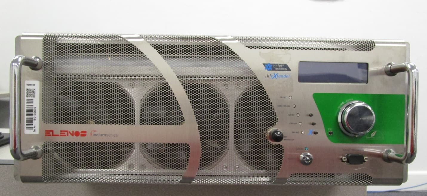
DDEETG5000
Mar 24, 2020FM BROADCAST TRANSMITTER
Equipment Class
TBC - Licensed Broadcast Station Transmitter
DDE7EPTX-STX500
May 05, 2014500W LPFM Broadcast Transmitter
Equipment Class
TBC - Licensed Broadcast Station Transmitter
DDE7EPTX-STX60
Aug 22, 201360W LPFM Broadcast Transmitter
Equipment Class
TBC - Licensed Broadcast Station Transmitter