DI2CT-EM2503ZigBee Module
Computime Limited
Click to zoom
Application Details
- Equipment Class
- DXX - Part 15 Low Power Communication Device Transmitter
- Date of Grant
- Jul 02, 2007
- Application Purpose
- Original Equipment
- Date of Application
- Jun 05, 2007
- Equipment Note
- ZigBee Module
- Frequency Range
- 2405.00000000 - 2480.00000000
- Company
- Computime Limited
- Country
- Hong Kong
Documents & Files
Document Text
Text extracted from the exhibit documents filed with the FCC. Open a document above to read the original.
Users Manual
CT-EM250 ZigBee-Ready RF Transceiver Modules Computime Ltd. All rights reserved Confidential Page 1 of 15 ZigBee- Ready SoC RF Transceiver Modules Table of Content General Description....................................................................................2 Applications...............................................................................................2 Features...................................................................................................2 Absolute Maximum Ratings...........................................................................3 Recommended Operating Conditions..............................................................3 Electrical Specifications................................................................................3 Introduction................................................................................................5 Typical Application Block...............................................................................5 Pin Assignment...........................................................................................6 Block Diagram............................................................................................8 Circuit Description.......................................................................................8 SIF Module Programming and Debug Interface.................................................9 Power Management....................................................................................9 RF Frequency, Output Power Levels and Data Rates.......................................10 Antenna Design Considerations....................................................................11 PCB Layout Recommendations....................................................................13 FCC Approvals..........................................................................................13 FCC statement....................................... .................................................14 Operating description.................................................................................14 Mechanical Dimensions..............................................................................15 Ordering Information..................................................................................15 Document Revision History..........................................................................15 CT-EM250 ZigBee-Ready RF Transceiver Modules Computime Ltd. All rights reserved Confidential Page 2 of 15 ZigBee- Ready SoC RF Transceiver Modules General Description The CT-EM250 SoC RF Transceiver Modules is a compact surface mounted module specially designed for Ember’s ZigBee™ protocol stack for wireless networks, EmberZNet, based on IEEE 802.15.4 standard in the 2.4GHz world-wide ISM band. It provides 16 channels and compliant PHY and MAC layers. The complete module is only 20.32 x 25.52 x 3 mm(integrated antenna version)and 20.32 x 19.53 x 3 mm (External Antenna version). They both integrate a 2.4GHz, IEEE 802.15.4-compliant transceiver with a 16-bit XAP2b microprocessor. They consist of integrated Flash and RAM memory and peripherals. A number of peripherals such as GPIO, UART, SPI, I2C, ADC, and general purpose timers are integrated to support user-defined applications. Applications Home automation & building control Home appliances & alarms Monitoring of remote systems Security systems & lighting controls Sensor data capture in embedded networks Features Complete ZigBee-ready module with or without integrated antenna IEEE 802.15.4 compliant PHY and MAC layer 12MHz XAP2b 16-bit microcontroller core 128kB Flash and 5kB RAM, emulation EEPROM 17 GPIO , 4 channel 12 bit ADC UART, SPI, I 2 C and debug interfaces External 32.768 kHz real time clock or internal RC oscillator for timer High performance direct sequence spread spectrum (DSSS) RF transceiver 16 channels in the 2.4 GHz ISM band on-chip regulator for 2.1-3.6V operation, two sleep low power modes CT-EM250 ZigBee-Ready RF Transceiver Modules Computime Ltd. All rights reserved Confidential Page 3 of 15 Absolute Maximum Ratings Parameter Test Conditions Min. Max. Unit Regulator voltage (VDD_PADS) - 0.3 3.6 V Voltage on any GPIO[16:0], SIF_CLK, SIF_MISO, SIF_MOSI, nSIF_LOAD, OSC32A, OSC32B, nRESET, - 0.3 VDD_PADS+ 0.3 V Storage temperature - 40 + 140 °C Under no circumstances should the absolute maximum ratings given above be violated. Stress exceeding one or more of the limiting values may cause permanent damage to the device. Recommended Operating Conditions Parameter Test Conditions Min. Typ. Max. Unit Regulator input voltage (VDD_PADS) 2.1 3.6 V Core input voltage (VDD_24MHZ, VDD_VCO, VDD_RF, VDD_IF, VDD_PADSA, VDD_FLASH, VDD_PRE, VDD_SYNTH, VDD_CORE) 1.7 1.8 1.9 V Temperature range - 40 + 85 °C Electrical Specifications T=25 °C, VCC = 3.0V, fo=2450Mhz, if nothing else stated. Parameter Min. Typ. Max Unit Condition / Note Operating frequency 2405 2480 M Programmable in 5 MHz steps for IEEE 802.15.4 compliance Number of channels 16 For IEEE 802.15.4 compliance Channel spacing 5 MHz For IEEE 802.15.4 compliance Input/output impedance 50 Ohm Data rate 250 kbit/s DSSS chip rate 2 Mc/s Frequency stability +/-40 ppm Transmit power -32 5 dBm Programmable from firmware Harmonics 2nd harmonic TBD dBm 3rd harmonic TBD dBm CT-EM250 ZigBee-Ready RF Transceiver Modules Computime Ltd. All rights reserved Confidential Page 4 of 15 Parameter Min. Typ. Max Unit Condition / Note Spurious emission, TX 30 – 1000 MHz TBD dBm 1-12.75 GHz TBD 1.8-1.9 GHz TBD 5.15-5.3 GHz TBD Complies with EN 300 328, EN 300 440, FCC CRF47 Part 15 and ARIB STD-T66 Sensitivity -98 dBm PER = 1% Boost Mode Adjacent channel rejection +/-5 MHz 35/35 dB IEEE 802.15.4 signal at - 82dBm Adjacent channel rejection +/-10 MHz 40/40 dB IEEE 802.15.4 signal at - 82dBm Co-channel rejection -6 dB IEEE 802.15.4 signal at - 82dBm Spurious emission, RX 30 -1000 MHz TBD 1-12.…
Text truncated - open the document above for the full version.
Cover Letter(s)
ADT (Shanghai) Corporation 2F, Building C, No. 1618, Yishan Rd., 201103, Shanghai, China Jun. 5, 2007 FCC ID: DI2CT-EM2503 The following lists are the answers for the comments on Jun. 4, 2007, please kindly have a review on it: 1. Users Manual needs Pt. 15.21 statement. Changes or modifications not expressly approved by the party responsible for compliance could void the user's authority to operate the equipment. RE: Please see Pg. 14 of (DI2CT-EM2503)UserMan.rev1. 2. Please upload label location photo exhibit. RE: Please see Pg. 14 of (DI2CT-EM2503)UserMan.rev1. When the CT-EM2503 module is integrated inside another device/product, then the outside surface of that device/product must display a label referring to the enclosed module. This exterior label can use wording such as “Contains Transmitter Module FCC ID: DI2CT-EM2503” or “Contains FCC ID: DI2CT-EM2503” although any similar wording that expresses the same meaning may be used. Thank you very much.
Cover Letter(s)
ADT (Shanghai) Corporation 2F, Building C, No. 1618, Yishan Rd., 201103, Shanghai, China Jun. 5, 2007 FCC ID: DI2CT-EM2503 The following lists are the answers for the comments on Jun. 4, 2007, please kindly have a review on it: 1. Users Manual needs Pt. 15.21 statement. Changes or modifications not expressly approved by the party responsible for compliance could void the user's authority to operate the equipment. RE: Please see Pg. 14 of (DI2CT-EM2503)UserMan.rev1. 2. Please upload label location photo exhibit. RE: Please see Pg. 14 of (DI2CT-EM2503)UserMan.rev1. When the CT-EM2503 module is integrated inside another device/product, then the outside surface of that device/product must display a label referring to the enclosed module. This exterior label can use wording such as “Contains Transmitter Module FCC ID: DI2CT-EM2503” or “Contains FCC ID: DI2CT-EM2503” although any similar wording that expresses the same meaning may be used. Thank you very much.
Test Report
FCC ID: DI2CT-EM2503 Report No.: 070503FIA01 1 FCC TEST REPORT REPORT NO.: 070503FIA01 MODEL NO.: CT-EM2503 RECEIVED: May. 11, 2007 TESTED: May. 14 ~ May. 25, 2007 ISSUED: May. 30, 2007 APPLICANT: Computime Limited ADDRESS: 17/F. Great Eagle Centre, 23 Harbour Road Wanchai, Hong Kong ISSUED BY: ADT (Shanghai) Corporation ADDRESS: 2F, Building C, No.1618, Yishan Rd., 201103, Shanghai, China This test report consists of 20 pages in total. It may be duplicated completely for legal use with the approval of the applicant. It should not be reproduced except in full, without the written approval of our laboratory. The client should not use it to claim product endorsement by A2LA or any government agencies. The test results in the report only apply to the tested sample. ADT (Shanghai) Corporation. V 1.0 FCC ID: DI2CT-EM2503 Report No.: 070503FIA01 2 Table of Contents 1 CERTIFICATION............................................................................................ 3 2 SUMMARY OF TEST RESULTS...................................................................... 4 2.1 MEASUREMENT UNCERTAINTY................................................................... 4 3 GENERAL INFORMATION............................................................................. 5 3.1 GENERAL DESCRIPTION OF EUT................................................................. 5 3.2 DESCRIPTION OF TEST MODES................................................................... 5 3.3 GENERAL DESCRIPTION OF APPLIED STANDARDS..................................... 7 3.4 DESCRIPTION OF SUPPORT UNITS............................................................. 7 4 EMISSION TEST........................................................................................... 8 4.1 CONDUCTED EMISSION MEASUREMENT.................................................... 8 4.1.1 LIMITS OF CONDUCTED EMISSION MEASUREMENT................................... 8 4.1.2 TEST RESULTS............................................................................................. 8 4.2 RADIATED EMISSION MEASUREMENT......................................................... 9 4.2.1 LIMITS OF RADIATED EMISSION MEASUREMENT........................................ 9 4.2.2 TEST INSTRUMENTS.................................................................................. 10 4.2.3 TEST PROCEDURE.................................................................................... 11 4.2.4 DEVIATION FROM TEST STANDARD........................................................... 11 4.2.5 TEST SETUP.............................................................................................. 12 4.2.6 EUT OPERATING CONDITIONS................................................................... 12 4.2.7 TEST RESULTS........................................................................................... 13 4.3 BAND EDGES MEASUREMENT................................................................... 17 4.3.1 LIMITS OF BAND EDGES MEASUREMENT.................................................. 17 4.3.2 TEST INSTRUMENTS.................................................................................. 17 4.3.3 TEST PROCEDURE.................................................................................... 17 4.3.4 DEVIATION FROM TEST STANDARD........................................................... 17 4.3.5 EUT OPERATING CONDITION..................................................................... 17 4.3.6 TEST RESULTS........................................................................................... 17 5 PHOTOGRAPHS OF THE TEST CONFIGURATION....................................... 18 6 PHOTOGRAPHS OF THE EUT..................................................................... 19 7 APPENDIX - INFORMATION ON THE TESTING LABORATORY..................... 20 FCC ID: DI2CT-EM2503 Report No.: 070503FIA01 3 1 CERTIFICATION PRODUCT: Zigbee module MODEL NO.: CT-EM2503 APPLICANT: Computime Limited TESTED: May. 14 ~ May. 25, 2007 TEST ITEM: ENGINEERING SAMPLE STANDARDS: 47 CFR Part 15, Subpart C (Section 15.249), ANSI C63.4-2003 The above equipment has been tested by ADT (Shanghai) Corporation, and found compliance with the requirement of the above standards. The test record, data evaluation & Equipment Under Test (EUT) configurations represented herein are true and accurate accounts of the measurements of the sample’s EMC characteristics under the conditions specified in this report. TECHNICAL ACCEPTANCE : , DATE:May. 30, 2007 Vivian Hsu Engineering Supervisor APPROVED BY : , DATE: May. 30, 2007 Wallace Pan Director of Operations FCC ID: DI2CT-EM2503 Report No.: 070503FIA01 4 2 SUMMARY OF TEST RESULTS The EUT has been tested according to the following specifications: APPLIED STANDARD: 47 CFR Part 15, Subpart C Standard Paragraph Test Type ResultRemark 15.207 Conducted Emission Test N/A Refer to 4.1.2 15.249 Radiated Emission Test PASS Minimum passing margin is –1.04 dB at 2405.03 MHz 15.249(d) Band Edge Measurement PASSMeet the requirement of limit 2.1 MEASUREMENT UNCERTAINTY Where relevant, the following measurement uncertainty levels have been estimated for tests performed on the EUT as specified in CISPR 16-4: Measurement Value Conducted emissions 1.8dB Radiated emissions 3.2dB FCC ID: DI2CT-EM2503 Report No.: 070503FIA01 5 3 GENERAL INFORMATION 3.1 GENERAL DESCRIPTION OF EUT PRODUCT Zigbee module MODEL NO. CT-EM2503 POWER SUPPLY 3.6Vdc from control board POWER CABLE SUPPLIED 0.2m, non-shielded, non-detachable MODULATION TYPE DSSS FREQUENCY RANGE OF OPERATION 2.405 ~ 2.480 MHz CHANNEL SEPARATION 5 MHz NUMBER OF CHANNEL 16 ANTENNA TYPE Soldered on PCB DATA CABLE SUPPLIED N/A I/O PORTS N/A NOTE: The above EUT information was declared by manufacturer and for more detailed features description, please refer to the manufacturer's specifications or User's Manual. 3.2 DESCRIPTION OF TEST MODES Four channels are provided to this EUT: Channel Frequency MHz Channel Frequency MHz 1 2405…
Text truncated - open the document above for the full version.
Contact Information
Applicant
Philip Chung(Reliability Manager)
Technical Contact
ADT ShanghaiWallace Pan
[email protected]86-21-6465-9091
2F Building C, No. 1618 Yishan Rd. · Shanghai · China
Test Firm
BUREAU VERITAS ADT (Shanghai) CorporationZhaoqian YU
Technical Specifications
| # | Rule Parts | Frequency Range | Power Output |
|---|---|---|---|
| 1 | 15C | 2.40 GHz - 2.48 GHz | - |
Other Applications from Computime Limited

DI2RCSTA-TX
Dec 04, 2014Transmitter
Equipment Class
DSC - Part 15 Security/Remote Control Transmitter
DI2RCST-RX
Dec 04, 2014Receiver
Equipment Class
CYY - Communications Receiver used w/Pt 15 Transmitter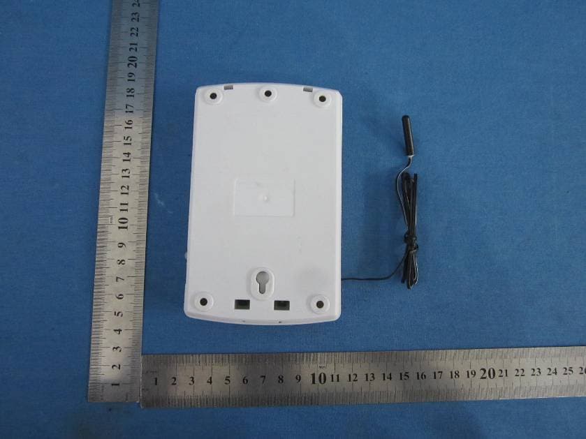
DI2AAHZT3A
May 29, 2013Wireless Thermostat Controller
Equipment Class
DXX - Part 15 Low Power Communication Device Transmitter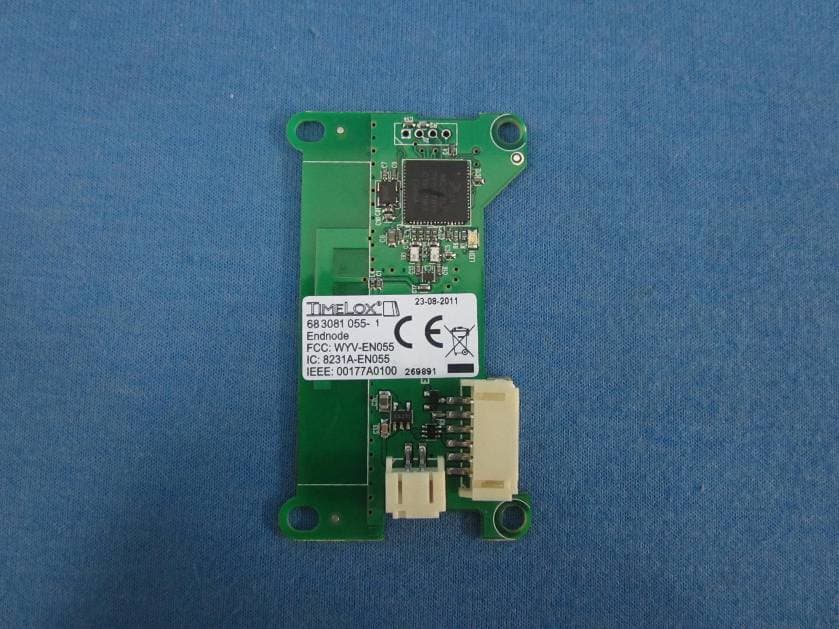
DI2AAHZT21
May 27, 2013Wireless Thermostat
Equipment Class
DXX - Part 15 Low Power Communication Device Transmitter
DI2-TDL6192
Oct 07, 2012US SMART PLUG
Equipment Class
DTS - Digital Transmission System