DI2CTLM901900MHz Radio Telemetry Module
Computime Limited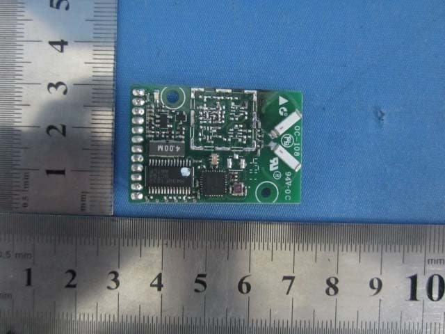
Click to zoom
Application Details
- Equipment Class
- DTS - Digital Transmission System
- Date of Grant
- Mar 05, 2012
- Application Purpose
- Original Equipment
- Date of Application
- Mar 05, 2012
- Equipment Note
- 900MHz Radio Telemetry Module
- Frequency Range
- 906.00000000 - 924.00000000
- Company
- Computime Limited
- Country
- Hong Kong
Documents & Files
Document Text
Text extracted from the exhibit documents filed with the FCC. Open a document above to read the original.
Users Manual
4700 Duke Drive, Suite 200 Ultra-Long-Range, General Purpose 900MHz Radio Telemetry Module 12 April-2011 Revision 1.1 Cincinnati Technologies 4700 Duke Dr. Suite 200 Mason, OH 45040 4700 Duke Drive, Suite 200 900 MHz Radio Telemetry Module Description This document describes the features and architecture for a general purpose 900 MHz telemetry transceiver module with exceptionally long range and reliable communications. Architecture Radio Standard and IC Selection The module is designed around the Atmel AT86RF212 802.15.4 transceiver IC. The 802.15.4 radio standard is an especially good choice as it provides for operation under the FCC CFR 15.247 spread spectrum rules, at significantly higher transmit power levels than would otherwise be allowed. The engineers at Cincinnati Technologies have engaged in the development of spread spectrum radio products and technologies for two decades, beginning with the design and manufacture of the first spread spectrum residential cordless telephone in 1992. Transmit Power Level For small, low duty cycle battery-powered applications transmitters operating at 50-100 milliwatts have been found to work well. It is high enough to achieve excellent range and coverage but low enough in DC power consumption to work well with AA cells. Data Rate and Receiver Sensitivity The AT86RF212 transmitted data rate is software selectable from 20 kbits/second to 1000 kbits/second. Higher data rates will yield longer battery life due to shorter transmitter on times. Lower data rates yield better receiver sensitivity and longer range. This tradeoff is easily optimized for each application. Integrated Diversity Antennas The benefits gained by use of two antennas are twofold. First, in environments rich in RF reflections, a phenomenon known as multi-path fading will frequently reduce the received signal level. A second antenna with different radiation characteristics will have different fades. The second benefit is based on the fact that antennas do not perform equally in all directions. By using two antennas with pattern nulls in different directions the module can choose to operate with the antenna with the lowest path loss to the far end. 4700 Duke Drive, Suite 200 Frequency Agility Incorporation of automatic ability to change operating frequency helps the radio pair avoid disruption due to on-channel interference. FCC rules mandate that products must tolerate occasional interference. One of the best strategies for doing so is avoidance. Radio Control It is desirable that integration of this module into various products be as simple as possible. This is achieved by use of the microcontroller to manage many basic radio and network functions. Interface Pin # Pin Type Description 1 GND P Ground 2 VCC P Power supply 3 SLEEP I Sleep mode input 4 SCK I SPI clock 5 SDI DI SPI data input 6 SDO DO SPI data output 7 CS I SPI chip select 8 TX DO UART Tx 9 RX DI UART Rx 10 RESET I Reset 11 INT O Interrupt request output 12 GPIO I/O May be used for standalone applications Electrical Specifications Transmit Current 200mA max Receive Current 15 mA max Sleep Current 5 uA max Radiated Transmit Power 22.97 dBm EIRP typical Radiated Receive Sensitivity 50 dBuV/m typical at 40 kbits/second 4700 Duke Drive, Suite 200 FCC STATEMENT: 1. This device complies with part 15 of the FCC Rules. Operation is subject to the following two conditions: (1) This device may not cause harmful interference, and (2) this device must accept any interference received, including interference that may cause undesired operation. 2. Changes or modifications not expressly approved by the party responsible for compliance could void the user's authority to operate the equipment. NOTE: This equipment has been tested and found to comply with the limits for a Class B digital device, pursuant to Part 15 of the FCC Rules. These limits are designed to provide reasonable protection against harmful interference in a residential installation. This equipment generates, uses and can radiate radio frequency energy and, if not installed and used in accordance with the instructions, may cause harmful interference to radio communications. However, there is no guarantee that interference will not occur in a particular installation. If this equipment does cause harmful interference to radio or television reception, which can be determined by turning the equipment off and on, the user is encouraged to try to correct the interference by one or more of the following measures: -- Reorient or relocate the receiving antenna. -- Increase the separation between the equipment and receiver. -- Connect the equipment into an outlet on a circuit different from that to which the receiver is connected. -- Consult the dealer or an experienced radio/TV technician for help. FCC Radiation Exposure Statement The modular can be installed or integrated in mobile or fix devices only. This modular cannot be installed in any portable device, for example, USB dongle like transmitters is forbidden. This modular complies with FCC RF radiation exposure limits set forth for an uncontrolled environment. This transmitter must not be co-located or operating in conjunction with any other antenna or transmitter. This modular must be installed and operated with a minimum distance of 20 cm between the radiator and user body. If the FCC identification number is not visible when the module is installed inside another device, then the outside of the device into which the module is installed must also display a label referring to the enclosed module. This exterior label can use wording such as the following: “Contains Transmitter Module FCC ID: DI2CTLM901 when the module is installed inside another device, the user manual of this device must contain below warning statements; 1. This device complies with Part 15 of the FCC Rules. Operation is subject to the following two conditions: 4700 Duke Drive, Suite 200 (1) This device may not cause harmful interference. (2) This device m…
Text truncated - open the document above for the full version.
Cover Letter(s)
Computime Limited 17/F, Great Eagle Centre, 23 Harbour Road, Wanchai, Hong Kong DATE :2012-02-28 Nemko Canada Inc 303 River Road Ottawa, Ontario, Canada K1V 1H2 Attn: Director of Certification Authority to Act as Agent On our behalf, I appoint Global United Technology Services Co., Ltd. 2nd Floor, Block No.2, Laodong Industrial Zone, Xixiang Road Baoan District Shenzhen Guangdong to act as our agent in the preparation of this application for equipment certification. I certify that submitted documents properly describe the device or system for which equipment certification is sought. I also certify that each unit manufactured, imported or marketed, as defined in the Federal Communications Commission’s regulations will have affixed to it a label identical to that submitted for approval with this application. For instances where our authorized agent signs the application for certification on our behalf, I acknowledge that all responsibility for complying with the terms and conditions for certification, as specified by Nemko Canada Inc, still resides with Computime Limited and 17/F, Great Eagle Centre, 23 Harbour Road, Wanchai, Hong Kong Dated this Day of 02/28/2012 Agency agreement expiration date: 02/28/2013 By: Philip Chung Signature Printed Title: Reliability Manager On behalf of : Computime Limited Telephone: 852 2660 0464
Cover Letter(s)
Computime Limited 17/F, Great Eagle Centre, 23 Harbour Road, Wanchai, Hong Kong 2012-02-28 Equipment Autorisation Division Federal Communications Commission 7435 Oakland Mills Road Columbia, MD 21046 FCC ID: DI2CTLM901 Product Name: 900MHz Radio Telemetry Module Request for Confidentiality Pursuant to Sections 0.457 and 0.459 of the commissions rules, we hereby request that the following documents be held confidential: • Schematics • Block diagram • Operational Description These materials contain trade secrets and proprietary information and are not customarily released to the public. The public disclosure of this information might be harmful to the company and provide unjustified benefits to our competitors. Dated this 02/28/2012 By: Philip Chung Signature Printed Title: Reliability Manager On behalf of : Computime Limited Telephone: 852 2660 0464
Cover Letter(s)
Modular Approval Declaration Letter Computime Limited 02/28/2012 900MHz Radio Telemetry Module FCC ID : DI2CTLM901 is seeking FCC Authorization as a Single Modular transmitter / Single Limited Modular Approval (Please check one). The EUT meets the requirements for Single Modular approval / Single Limited Modular Approval (please check one) as detailed in FCC public Notice DA00-1407. Compliance to each of the requirements is described below : Questions are: 1. “The modular transmitter must have its own RF shielding.” Yes / No 2. “The modular transmitter must have buffered modulation/data inputs.” Yes / No 3. “The modular transmitter must have its own power supply regulation.” Yes / No 4. “The modular transmitter must comply with the antenna requirements of section 15.203 and 15.204(c).” Yes / No 5. “The modular transmitter must be tested in a stand-alone configuration.” Yes / No 6. “The modular transmitter must be labeled with its own FCC ID number.” Yes / No 7. “The modular transmitter must comply with any specific rule or operating requirements applicable to the transmitter and the manufacture must provide adequate instruction along with the module to explain any such requirements.” Yes / No 8. “The modular transmitter must comply with any applicable RF exposure requirements.” Yes / No Note: (1) LMA may be granted when one or more of the requirements in the table above cannot be demonstrated. LMA will also be issued in those instances where applicants can demonstrate that they will retain control over the final installation of the device, such that compliance of the end product is assured. In such cases, an operating condition on the LMA for the module must state that the module is only approved for use when installed in devices produced by a specific manufacturer. When LMA is sought, the application for equipment certification must specifically state how control of the end product into which the module will be installed, and will be maintained, such that full compliance of the end product is always ensured. (2) Host devices which contain separately certified modules do not need to be recertified, provided that they meet the following conditions: (i) The host device, as a stand-alone unit without any separately certified modules, complies with all applicable Radio Standards Specifications. (ii) The host device and all the separately certified modules it contains jointly meet the RF exposure compliance requirements of RSS-102, if applicable. (iii) The host device complies with the certification labeling requirements of each of the modules it contains. Note 1: Compliance of a module in its final configuration is the responsibility of the applicant. A host device will not be considered certified if the instructions regarding antenna configuration provided in the original description, of one or more separately certified modules it contains, were not followed. Example: A separately certified low-power transceiver module using Bluetooth technology which is housed in a desktop computer, laptop or peripheral does not require the overall system to be recertified, if the desktop computer, laptop or peripheral, as a stand-alone unit, complies with all applicable technical standards. Client’s signature Client’s name / title Philip Chung / Reliability Manager Contact information / address Tel: 852 2660 0464 E-mail: [email protected] Address: 17/F, Great Eagle Centre, 23 Harbour Road, Wanchai, Hong Kong (Company letter head) (Date) mm/dd/yy (Product name) IC ID : , is seeking IC Authorization as a modular transmitter / Limited Modular Transmitter (Please check one). The EUT meets the requirements for modular approval / Limited Modular Approval (Please check one) as detailed in RSS GEN. Compliance to each of the requirements is described below: * Please provide a detailed explanation if the answer is “No.” a. The radio elements must have the radio frequency circuitry must be shielded. Physical/discrete and tuning capacitors may be located external to the shield, but must be on the module assembly. Yes / No b. The module shall have buffered modulation/data input(s) (if such inputs are provided) to ensure that the module will comply with the requirements set out in the applicable RSS standard under conditions of excessive data rates or over-modulation. Yes / No c. The module shall have its own power supply regulation on the module. This is to ensure that the module will comply with the requirements set out in the applicable standard regardless of the design of the power supplying circuitry in the host device which houses the module Yes / No d. The module shall comply with the provisions for external power amplifiers and antennas detailed in this standard. The equipment certification submission shall contain a detailed description of the configuration of all antennas that will be used with the module. Yes / No e. The module shall be tested for compliance with the applicable standard in a stand-alone configuration, i.e. the module must not be inside another device during testing Yes / No f. The module shall comply with the Category I equipment labelling requirements. Yes / No g. The module shall comply with applicable RSS-102 exposure requirements, which are based on the intended use/configurations. Yes / No h. (h) Is the modular device for an Industry Canada licensed exempt service? Yes / No Note: (3) LMA may be granted when one or more of the requirements in the table above cannot be demonstrated. LMA will also be issued in those instances where applicants can demonstrate that they will retain control over the final installation of the device, such that compliance of the end product is assured. In such cases, an operating condition on the LMA for the module must state that the module is only approved for use when installed in devices produced by a specific manufacturer. When LMA is sought, the application for equipment certification must specifically state how control of the end product into whi…
Text truncated - open the document above for the full version.
ID Label/Location Info
Label size: 23mm*13mm
ID Label/Location Info
Label Location
Test Report
Global United Technology Services Co., Ltd. Report No: GTSE12020007401 Authorized Signature: Stephen Guo Laboratory Manager This report details the results of the testing carried out on one sample. The results contained in this test report do not relate to other samples of the same product and does not permit the use of the GTS product certification mark. The manufacturer should ensure that all products in series production are in conformity with the product sample detailed in this report. This report may only be reproduced and distributed in full. If the product in this report is used in any configuration other than that detailed in the report, the manufacturer must ensure the new system complies with all relevant standards. Any mention of GTS International Electrical Approvals or testing done by GTS International Electrical Approvals in connection with, distribution or use of the product described in this report must be approved by GTS International Electrical Approvals in writing. This document cannot be reproduced except in full, without prior written approval of the Company. Any unauthorized alteration, forgery or falsification of the content or appearance of this document is unlawful and offenders may be prosecuted to the fullest extent of the law. Unless otherwise stated the results shown in this test report refer only to the sample(s) tested and such sample(s) are retained for 90 days only.” 1 Cover Page FCC REPORT Applicant: Computime Limited Address of Applicant: 17/F, Great Eagle Centre, 23 Harbour Road, Wanchai, Hong Kong Equipment Under Test (EUT) Product Name: 900MHz Radio Telemetry Module Model No.: CTLM901 FCC ID: DI2CTLM901 Applicable standards: FCC CFR Title 47 Part 15 Subpart C Section 15.247:2010 Date of sample receipt: Feb. 21, 2012 Date of Test: Feb. 21 - 23, 2012 Date of report issued: Feb. 25, 2012 Test Result : PASS * * In the configuration tested, the EUT complied with the standards specified above. Report No: GTSE12020007401 Global United Technology Services Co., Ltd. Project No.: GTSE120200074RF 2nd Floor, Block No.2, Laodong Industrial Zone, Xixiang Road Baoan District, Shenzhen, China 518102 Telephone: +86 (0) 755 2779 8480 Fax: +86 (0) 755 2779 8960 Page 2 of 32 2 Version Version No. Date Description 00 Feb. 25, 2012 Original Prepared By: Date: Feb. 25, 2012 Project Engineer Check By: Date: Feb. 25, 2012 Reviewer Report No: GTSE12020007401 Global United Technology Services Co., Ltd. Project No.: GTSE120200074RF 2nd Floor, Block No.2, Laodong Industrial Zone, Xixiang Road Baoan District, Shenzhen, China 518102 Telephone: +86 (0) 755 2779 8480 Fax: +86 (0) 755 2779 8960 Page 3 of 32 3 Contents Page 1 COVER PAGE..............................................................................................................................................................1 2 VERSION.......................................................................................................................................................................2 3 CONTENTS...................................................................................................................................................................3 4 TEST SUMMARY.........................................................................................................................................................4 5 GENERAL INFORMATION........................................................................................................................................5 5.1 CLIENT INFORMATION............................................................................................................................................5 5.2 GENERAL DESCRIPTION OF E.U.T........................................................................................................................5 5.3 TEST MODE............................................................................................................................................................7 5.4 TEST FACILITY.......................................................................................................................................................7 5.5 TEST LOCATION.....................................................................................................................................................7 5.6 OTHER INFORMATION REQUESTED BY THE CUSTOMER.......................................................................................7 5.7 DESCRIPTION OF SUPPORT UNITS........................................................................................................................7 5.8 TEST INSTRUMENTS LIST.......................................................................................................................................8 6 TEST RESULTS AND MEASUREMENT DATA.....................................................................................................9 6.1 ANTENNA REQUIREMENT:......................................................................................................................................9 6.2 CONDUCTED EMISSIONS.....................................................................................................................................10 6.3 CONDUCTED PEAK OUTPUT POWER..................................................................................................................13 6.4 6DB OCCUPY BANDWIDTH..................................................................................................................................15 6.5 POWER SPECTRAL DENSITY...............................................................................................................................17 6.6 SPURIOUS EMISSION...........................................................................................................................................19 6.6.1 Conducted Emission Method.................................................................................…
Text truncated - open the document above for the full version.
Test Setup Photos
Radiated Emission
Contact Information
Applicant
Philip Chung(Reliability Manager)
Technical Contact
Global United Technology Services Co., Ltd.Hans Hu
[email protected]+86-0755-2779 8480
2nd Floor, Block No.2, Laodong Industrial Zone, · Shenzhen · China
Non-Technical Contact
Global United Technology Services Co., Ltd.Crystal Zhang
[email protected]+86-0755-2779 8480
Test Firm
Global United Technology Service Co., LtdRobinson Lo
Technical Specifications
| # | Rule Parts | Frequency Range | Power Output |
|---|---|---|---|
| 1 | 15C | 906 MHz - 924 MHz | 198.00 mW |
Other Applications from Computime Limited

DI2RCSTA-TX
Dec 04, 2014Transmitter
Equipment Class
DSC - Part 15 Security/Remote Control Transmitter
DI2RCST-RX
Dec 04, 2014Receiver
Equipment Class
CYY - Communications Receiver used w/Pt 15 Transmitter
DI2AAHZT3A
May 29, 2013Wireless Thermostat Controller
Equipment Class
DXX - Part 15 Low Power Communication Device Transmitter
DI2AAHZT21
May 27, 2013Wireless Thermostat
Equipment Class
DXX - Part 15 Low Power Communication Device Transmitter
DI2-TDL6192
Oct 07, 2012US SMART PLUG
Equipment Class
DTS - Digital Transmission System