DI2GES2181Energy Saving Thermostat
Computime Limited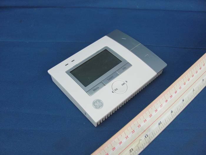
Click to zoom
Application Details
- Equipment Class
- DTS - Digital Transmission System
- Date of Grant
- Jul 27, 2010
- Application Purpose
- Original Equipment
- Date of Application
- Jul 27, 2010
- Equipment Note
- Energy Saving Thermostat
- Frequency Range
- 2405.00000000 - 2480.00000000
- Company
- Computime Limited
- Country
- Hong Kong
Documents & Files
Document Text
Text extracted from the exhibit documents filed with the FCC. Open a document above to read the original.
Users Manual
Energy Saving Thermostat [Insert product picture] Instruction Manual Model no. GES2181 1 2 CONTENTS PRODUCT OVERVIEW The GES2181 Energy Saving Thermostat can connect to 3 Heat / 2 Cool conventional Heat Pump HVAC systems. The thermostat’s smart ZigBee™ technology enables it to communicate with your utility company so you can receive messages about energy saving events and price reductions. In addition, the easy‐to‐use interface makes it simple to control your energy consumption. SAFETY INSTRUCTIONS Purpose and correct use: • Read these instructions carefully and keep in a safe place for future reference. • Only an authorized, qualified installer should install this unit. All manual / safety instructions and electricity supplier’s regulations must be adhered to. • Only connect this unit to a 24‐volt A/C power source. • Do not install this unit at an altitude of over 2000 meters. • This standalone mounted electronic unit serves as a temperature control system only in dry, closed living and office spaces. Do not place the unit in a bathroom or area of excessive moisture. Do not allow the unit to get wet. • Place the unit in an easy‐to‐reach position where you can comfortably reach the buttons and view the screen. • Do not expose the unit to: temperatures below 5°C or above 40°C; humidity above 80% or pollution above level 2. • Do not expose the unit to voltage fluctuations of more than +/‐ 10%. • Clean the unit with a dry, soft cloth. Do not use solvents or aggressive cleaning agents. The manufacturer accepts no responsibility for damage caused by non‐observance of these instructions. Environmental Protection Unwanted electrical appliances can be recycled and should not be discarded along with regular household waste. Please help to support the conservation of resources and protect the environment by returning this appliance to your nearest collection centre (if available). INSTALLATION Please refer to Appendix for installation guide. HOME SCREEN The Home screen is the main display screen. If you do not press any buttons for 30 seconds, the thermostat will return to the Home screen. 3 Comment [Kairy1]: Added below The large temperature reading on the Home screen is the current temperature. The small temperature reading is your setpoint temperature. To quickly change the setpoint temperature: Press UP or DOWN. When you receive an event or message from the utility company, ‘Event’ or ‘Message’ appears on the bottom of the Home screen and advises how many events or messages you have received, and the event’s level of importance. SET HEAT/COOL MODE 1. When you are in the Home screen, press SYS and the screen opposite appears. 2. Press SYS repeatedly to select one of the following options: • ‘Heat’, ‘Cool’ or ‘Off’ (Conventional HAVC) • ‘Heat’, ‘Emer’ (Emergency Heating), ‘Cool’ or ‘Off’ (Heat pump HVAC) 3. Press MENU to confirm your selection and return to the Home screen. Note: Make sure you press MENU to confirm your changes or they will not be saved. SET FAN MODE 1. When you are in the Home screen, press FAN and the screen opposite appears. 2. Press FAN repeatedly to select ‘Fan On’ or ‘Fan Auto’. 3. Press MENU to confirm your selection and return to the Home screen. Notes: 4 e heating/cooling system is working. ur changes or they will not be saved. MAIN MENU SETTINGS een, press MENU and the screen opposite appears. • When the fan is set to ‘Auto’ it only runs when th • Make sure you press MENU to confirm yo 1. When you are in the Home scr 5 tions. s or they will not be saved. menu ility company, ‘Event’ or ‘Message’ appears on any events or messages you have received, and can view the details by repeatedly pressing INFO (see the ssages’ section for more information). o reject events: t All Events’. confirm. If you reject an event, a message t to reject it, press en. inue to reject all new n the system and any new events that must select ‘Accept Current Event’ as shown below. Current Event’ or ‘Accept All Events’. confirm. have ogram menu while you . Select and enter the Override menu. lect ‘Vacation’ and the screen SELECT to confirm. settings and ‘On’ to activate this function. d return to the previous screen. 2. Press UP or DOWN to scroll through the Main menu op 3. Press SELECT to enter a menu. Note: Make sure you press MENU to confirm your change Override When you receive an event or message from the ut the bottom of the Home screen and advises how m the event's level of importance. You ‘Viewing events and me In the Override menu, you can choose to accept or reject events and messages, and set the thermostat to ‘Vacation’ to override the programmed settings. T 1. Select and enter the Override menu. 2. Press UP or DOWN to select ‘Reject Current Event’ or ‘Rejec 3. Press SELECT to appears to ask if you are sure you wan SELECT to confirm the rejection or MENU to return to the previous scre Note: Once you have rejected a current event, the unit will cont have rejected all events, the unit will reject all events stored o may occur. To enable the unit to accept events once again, you or ‘Accept All Events’ events. If you To accept events: 1. Select and enter the Override menu. 2. Press UP or DOWN to select ‘Accept 3. Press SELECT to Note: The unit will automatically accept events unless you set it to reject events and vice‐versa. To set your vacation time: This setting will override your selected program settings in the Pr vacation. are on 1 2. Press UP or DOWN to se opposite appears. 3. Press 4. Use UP or DOWN to scroll through the press SYS or FAN to change a setting. You must set the ‘Vacation Mode’ to 5. Press MENU to confirm an 6 override your temperature setting when the new event setting saves energy, for example: a) In wintertime when the outdoor temperature is cold, you may set your vacation temperature to 10°C to prevent pipes from freezing. However, if the utility company sends an event to reduce the temperature to 8°C to save energy, it will override your vacation temperature and m…
Text truncated - open the document above for the full version.
Block Diagram
Zigbee thermostat For NEMA modifyFirst release ABCD DATED: Release: DATED: Approval:CHECKED: DATED: DATED: DRAWN: Gordon MikeLin Description COMPUTIME A3 2.0 1:1 4 4 REV: SIZE: SCH Name: COMPANY:TITLE: PCB Name: SHEET: OF SCALE: REVISION RECORD 1 2 3 4 5 6 DCBA DATE: LTR 2010-04-122010-4-12 12 2010-04-12 2010-01-12 GES2181 MCU PIC16FJ256 Display AC Power detect Temperature detect L Terminal detect Key input System SW setting Flash memory Relay output AT25DF161 RF Module CT-EM2606 LCM+BACKLIGHT+LED 32KHz Crystal 32MHz Crystal +3V +5V 24VAC XC6214 LDO MC34063 AC--DC Power Supply EEPROM AT25128 RTC RX-8025A
External Photos
INTERTEK TESTING SERVICE Report No.: HK10060857-1 Equipment Photographs Model : GES2181 (External) FCC ID: DI2GES2181 IC: 1700A-GES2181
ID Label/Location Info
Computi me Model: GES2181 FCC ID : DI 2GES2181 IC : 1700A-GES2181 This device co mplies with Part 15 of th e FCC Rules. Operation is subject to th e following two co ndi tions: (1) thi s device may not cause harmful interference, and (2) thi s device must accept any interference received, including interference that may cause undesired operation. 70x30 mm GES2181 FCC IC label Material:PET Background:Silver gray Font Color:Black Font:Arial General Electric Model: PCT1N00R0WW FCC ID : DI2GES2181 This device complies with Part 15 of the FCC Rules. Operation is subject to the following two conditions: (1) this device may not cause harmful interference, and (2) this device must accept any interference received, including interference that may cause undesired operation. GES2181 FCC IC label Material:PET Background:Silver gray Font Color:Black Font:Arial 50x25 mm IC : 1700A-GES2181
Internal Photos
INTERTEK TESTING SERVICE Report No.: HK10060857-1 Equipment Photographs Model : GES2181 (Internal) FCC ID: DI2GES2181 IC: 1700A-GES2181 INTERTEK TESTING SERVICE Report No.: HK10060857-1 Equipment Photographs Model : GES2181 (Internal) FCC ID: DI2GES2181 IC: 1700A-GES2181 INTERTEK TESTING SERVICE Report No.: HK10060857-1 Equipment Photographs Model : GES2181 (Internal) FCC ID: DI2GES2181 IC: 1700A-GES2181 INTERTEK TESTING SERVICE Report No.: HK10060857-1 Equipment Photographs Model : GES2181 (Internal) FCC ID: DI2GES2181 IC: 1700A-GES2181
Operational Description
Circuit Description Page 1 of 3 Circuit Description Model Number : PCT10100R0WW Model Name : GES2181 HOTPOINT MODEL AI Customer :GEA Customer Model Number : Department : CTL Revision : X1 Date :July.1-2010 Number of Pages : 3 Prepared by : ___________________(Mike Lin) Approved by : ___________________(Gordon Qian) Revision Rev. Date. Prepared by History X1 July.1-2010 Mike Lin Initial release Circuit Description Page 2 of 3 There are three key units in the product:the control unit,the RF module and the LCD display module. 1. Control unit The key part of the control unit is the MCU (U1). It is a 16-Bit built in 256KB flash microcontroller. Its responsibility is to control the whole product: a. Communicate with the RF module (U3). Exchange data (receive and transmit) via RF module. b. Send display information to LCD module. c. Receive the key press information from the key in the front panel. d. Indicate the status of the product via the LED. e. Communicate with the EEPROM and flash. f. Control the relay to drive the contactor of the HVAC. g. Read the ambient temperature. h. Communicate with the RTC. 2. RF module The RF module is a complete ZigBee-ready module with integrated antenna. Its responsibility is to exchange data (receive and transmit) via the 2.4 GHz ISM band RF net. For more details,read the reference specification of the RF module please. 3. LCD display module The LCD display module(J1) is a FSTN LCD. Its responsibility is to display the information from the MCU. 4. RTC U11 is a high stability crystal built-in real time clock module. It provides the real time to the MCU via I 2 C bus for the time display and calendar. 5. Relays There are six relays which are controlled by MCU. And these relays connect the 24VAC power to drive the contactor of the HVAC via terminal (J3). 6. L detect The pin mark symbol ”L” in the terminal (J3) is a system error input port for the MCU to get the information of the HVAC system. 7. Power detect Circuit Description Page 3 of 3 D2, Q6, R43, R38, C20, R30, C18 and R39 form the 24VAC power detection circuit for the MCU to get the information of the power supply status in AC24V system. 8. Thermal Sensor RT1 is a thermistor for MCU to get the ambient temperature information. 9. System switch SW1 is a switch for the user to select a HVAC system. 10. EEPROM/Flash U2 and U10 are memories for storage the program code, the status configured by user and other important information. 11. Program port The J2 is a combination program port for program the MCU and the RF module. 12. Power supply Pin RC and C of J3 is the power input (24VAC). D8 and associated circuit is the rectifier. Q8 and associated circuit is the voltage clip unit. U6 and associated is the DC-DC voltage regulation circuit. It outputs a +4.7VDC. U9 and associated circuit is the LDO voltage regulation circuit. It outputs a +3VDC to MCU, LCD, RF Module etc. - End - CT-EM2606 CIRCUIT DESCRIPTION 1. Power Supply: We can power on the unit though VBRD, because there is a 1.8V regulator in the chip (EM260) and regulate the input power supply to stable 1.8V, so the power supply can range from 2.7 to 3.6V DC. 2. EM260: The EM260 integrates a 2.4GHz IEEE 802.15.4-compliant transceiver with a 16-bit net processor(XAP2b core) to run EmberZnet. The transceiver utilizes an efficient architecture that exceeds the dynamic range requirements imposed by the IEEE 802.15.4-2003 standard by over 15dB. The integrated regulator, VCO, loop filter, and power amplifier keep the external component count low. 3. SKY65337: SKY65337 is high-efficiency Front-End Module for ZigBee and other 2.4GHz ISM band applications. It contains a 2400-2500MHz high-efficiency transmit path and a low-lose bidirectional path. The transmit path consists of an harmonic filter, an balun and an PA capable of providing +20dbm of power at the antenna port. The bidirectional path consists of a high isolation T/R switch and an balun for low-noise differential port. 4. TX/RX control: It is builded of Q1,Q2,R3,R4,R15,R16,R17. The signal of TX is low, U2 set up bidirectional path, U2 can be transmit and receive. The signal of TX is high, U2 set up transmit path. 5. Antenna: A PCB’s antenna is used to transmit and receive 2.4GHZ carrier signal ,The component of C2,C3,L3 are matched circuit for antenna. EM260 ZigBee/802.15.4 Network Processor Integrated 2.4GHz, IEEE 802.15.4-compliant trans- ceiver: • Robust RX filtering allows co-existence with IEEE 802.11g and Bluetooth devices • - 97.5dBm RX sensitivity (1% PER, 20byte packet) • + 3dBm nominal output power • Increased radio performance mode (boost mode) gives – 98.5dBm sensitivity and + 5dBm transmit power • Integrated VCO and loop filter • Secondary TX-only RF port for applications re- quiring external PA. Integrated IEEE 802.15.4 PHY and MAC Ember ZigBee-compliant stack running on the dedicated network processor Controlled by the Host using the EmberZNet Serial Protocol (EZSP) • Standard Serial Interface (allows for connection to a variety of Host mi- crocontrollers) Non-intrusive debug interface (SIF) Integrated hardware and software support for InSight Development Environment Dedicated peripherals and integrated memory Provides integrated RC oscillator for low power operation Three sleep modes: • Processor idle (automatic) • Deep sleep—1.0μA • Power down—1.0μA Watchdog timer and power-on-reset circuitry Integrated AES encryption accelerator Integrated 1.8V voltage regulator Always powered PacketTrace ADC RF_P,N Integrated Flash and RAM SIF_MISO HF OSC SIF Internal RC-OSC IO Controller Chip manager Regulator Bias Interrupt Controller RF_TX_ALT_P,N OSCA OSCB SIF_MOSI SIF_CLK nSIF_LOAD Encryption acclerator IF Network Processor (XAP2b) VREG_OUT Watchdog PA select LNA PA PA DAC MAC + Baseband TX_ACTIVE Sleep timer BIAS_R POR Network Processor Peripherals Serial Controller SYNTH SCLK MISOMOSI nSSEL LINK_ACTIVITY nHOST_INT nWAKE nRESET nSSEL_INT PTI_EN PTI_DATA SDBG Ember Corpora…
Text truncated - open the document above for the full version.
RF Exposure Info
INTERTEK TESTING SERVICE Report No.: HK10060857-1 FCC ID: DI2GES2181 RF Exposure Evaluation For Maximum Permissible Exposure (MPE) evaluation of the device, the maximum power density at 20 cm from this mobile transmitter shall be less than the General Population / Uncontrolled MPE limit in OET Bulletin 65. For the device of tested model of GES2181, the maximum conducted measured power (P) was 64.12mW. From these data, the exposed power density at a distance (R) of 20cm from the center of radiation of the antenna can be calculated according to OET Bulletin 65 as follow: The maximum peak conducted power = 64.12mW The power density at 20 cm from the antenna = P / 4πR 2 = 0.013 mWcm -2 The measured maximum field strength (FS) was 117.0 dBμV/m. The distance (D) between the antenna and the equipment under test (EUT) was 3 meters. From these data, the radiated (EIRP) can be calculated by: The radiated power = (FS*D) 2 / 30 mW = 150.4 mW The power density at 20 cm from the antenna = P / 4πR 2 = 0.03 mWcm -2 In the frequency range of 2.4-2.4835 GHz, the MPE limit is 1.0 mWcm -2 for general population and uncontrolled exposure. As the measured power density at 20cm from the transmitter is lower than the MPE limit, the compliance to the MPE limit can be ensured by indicating the minimum 20cm separation between the transmitter's radiating structures and body of the user or nearby persons. The following RF exposure statement is included in the user manual: “FCC RF Radiation Exposure Statement: This equipment complies with FCC RF radiation exposure limits set forth for an uncontrolled environment. This equipment should be installed and operated with a minimum distance of 20 centimeters between the radiator and your body.”
Schematics
Zigbee thermostat GES2181 2010-01-12 2010-04-12 21 2010-4-122010-04-12 LTR DATE: ABCD 654321 REVISION RECORD SCALE: SHEET: OF PCB Name: TITLE:COMPANY: SCH Name: SIZE: REV: 4 1 1:1 2.0 A3 COMPUTIME Description MikeLin Gordon DRAWN: DATED: DATED: CHECKED:Approval: DATED: Release: DATED: DCBA First releaseFor NEMA modify U1.11 U1.19 U1.26 U1.38 U1.57 J1.14 U2.8 HPHG STD HE HP:Heat pump systemSTD:Conventional systemHG:Gas heatingHE:Electrical heatingNormal mode :HP/HE U3.15 U10.8 1 CS1 2 RES 3 A0 4 WR 5 RD 6 RB0 7 RB1 8 RB2 9 RB3 10 RB4 11 RB5 12 RB6 13 RB7 14 VDD 15 VSS 16 VOUT 17 CAP3+ 18 CAP1- 19 CAP1+ 20 CAP2+ 21 CAP2- 22 V1 23 V2 24 V3 25 V4 26 V0 J1 LCM26 S1 UP S2 DOWN S3 SELECT S4 FAN S5 PROGRAM S6 MENU RT1 R115.6K 1%R124.3K 1% R13200K Q12N3904 D6 BACKLIGHT R1639 R17 1K R1 1K R2 1K R3 1K R20 1K R21 1K R22 1K C15100pF 1 SIF_CLK 2 SIF_MISO 3 SIF_MOSI 4 NSIF_LOAD 5 SDBG 6 LINK_ACTIVITY 7 GND 8 GND 9 GND 10 GND 11 GND 12 GND 13 IDLE_EN 14 GND 15 VDD 16 NRESET 17 MOSI 18 MISO 19 SCLK 20 VPA_EN 21 NRST 22 SSEL_INT/CTS 23 PTI_EN 24 PTI_DATA 25 TXD 26 NHOST-INT/RXD 27 NWAKE 28 GND U3 CT-EM2606 1 RE5 2 RE6 3 RE7 4 RG6 5 RG7 6 RG8 7 MCLR 8 RG9 9 VSS 10 VDD 11 RB5 12 RB4 13 RB3 14 RB2 15 RB1 16 RB0 48 RC14/SOSCO 47 RC13/SOSCI 46 RD0 45 RD11 44 RD10 43 RD9 42 RD8 41 VSS 40 OSC2/RC15 39 OSC1/RC12 38 VDD 37 SCL1/RG2 36 SDA1/RG3 35 RF6 34 RF2 33 RF3 49 RD1 50 RD2 51 RD3 52 RD4 53 RD5 54 RD6 55 RD7 56 VDDCORE/VCAP 57 ENVREG 58 RF0 59 RF1 60 RE0 61 RE1 62 RE2 63 RE3 64 RE4 32 RF5/SCL2 31 RF4/SDA2 30 RB15 29 RB14 28 RB13 27 RB12 26 VDD 25 VSS 24 RB11 23 RB10 22 RB9 21 RB8 20 AVSS 19 AVDD 18 RB7 17 RB6 U1 PIC24FJ256 R4 1K R510K C1 100nF D1 1N4148 D3TVS D4TVS 1 2 3 4 SW1 R6510K R7 510K R810K 1 CS 2 SO/SOI 3 WP 4 GND 8 VCC 7 HOLD 6 SCK 5 SI/SIO U2 AT25DF161 R910K R1010K R14 300 R15 300 2 1 Y1 32MHz C2 15pF C3 15pF 2 1 Y2 32KHz C4 15pF C5 15pF S7 SYS R24 1K C6 100nF C7 100nF C8 100nF C21 100nF C22 100nF C23 100nF C24 100nF 12345678910111213141516 J2 PROGRAM C25100nF C26100nF C27100nF C28100nF C29100nF C30100nF C31100nF C1910uF R28 0 R29 4.7K R46 300 C33220nF C34220nF C35220nF C362.2uF C372.2uF C32220nF C382.2uF C392.2uF C40220nF D5 R18300 R19300 R23300 12 S8 RESET C41100nF 8 VCC 1 CS 3 WP 7 HOLD 5 SI 2 SO 6 SCK 4 GND U10 AT25128N R494.7K C44100nF 1 3 2 4 D7 DILED R5310K +3V +3V +5V RD RG7 A0 RES RD A0 RES +3V +3V +3V YELLOW RB4 NRESET SSEL PGC&GREEN PGD&RED +3V NWAKE AC_DETECT L_DETECT +3V +3V RB14 RB15 SDA2 SCL2 +3V +3V +3V SDA2SCL2 +3V RB14RB15 MOSIMISO NHOST_INTDOWNUP +3V SELECTRD10 RD11 RD0_K5 RD1_K4 RD2_K3 RD3_K2 RD4_K1 SYS PROG FAN VCAP +3V MENU LCM_LED LCM_LED UPDOWNSELECTFANPROGMENUSYS SIF_CLK SIF_MISOSIF_MOSI NSIF_LOAD SDBGMOSIMISOSCLKSSEL PTI_EN PTI_DATA NHOST_INT NWAKE +3V SIF_MISOSDBGSIF_MOSISIF_CLKNSIF_LOADNRESETPTI_ENPTI_DATA +3V PGC&GREENPGD&REDTRST TRST +3V VCAP MCLR +3V SCLK RB9_K6 YELLOW PGD&RED PGC&GREEN +3V +3V +3V SDA2RB15SCL2 RB0 RB0 FOUTINTA NRESET Zigbee thermostat For NEMA modifyFirst release ABCD DATED: Release: DATED: Approval:CHECKED: DATED: DATED: DRAWN: Gordon MikeLin Description COMPUTIME A3 2.0 1:1 2 4 REV: SIZE: SCH Name: COMPANY:TITLE: PCB Name: SHEET: OF SCALE: REVISION RECORD 1 2 3 4 5 6 DCBA DATE: LTR 2010-04-122010-4-12 12 2010-04-12 2010-01-12 GES2181 1 SWC 2 SWE 3 TC 4 GND 8 DRC 7 IPK 6 VCC 5 CII U6 MC34063 + C9 10uF/50V + C10 220uF/50V C11100nF R25 0.33R D9 1N5819 C12470pF L1 220uH + C13 470uF/10V C14100nF R26 3.3K 1% R27 9.1K 1% 12 JP1 COM C B 1 B1 2 B2 3 B3 4 B4 5 B5 6 B6 7 B7 8 E 16 C1 15 C2 14 C3 13 C4 12 C5 11 C6 10 C7 9 COM U7 ULN2003A MOV1 MOV2 MOV3 MOV4 MOV5 MOV6 1 L 2 C 3 G 4 Y 5 Y2 6 W 7 W2/E 8 W3/O/B 9 RH 10 RC J3 COM C B 1 B1 2 B2 3 B3 4 B4 5 B5 6 B6 7 B7 8 E 16 C1 15 C2 14 C3 13 C4 12 C5 11 C6 10 C7 9 COM U8 ULN2003A K1-A K1-B 3 42 K2-C 8 79 K2-D K2-AK3-AK4-AK5-A K2-BK3-BK4-BK5-B 3 42 K5-C 8 79 K5-D 3 42 K1-C 8 79 K1-D 3 42 K4-C 8 79 K4-D 3 42 K3-C 8 79 K3-D + C16 470uF/10V C17100nF MOV7 E B C Q22N3906 E B C Q32N3906 Q4 2N3904 Q5 2N3904 R32 10K R33 10K R34 100K R35 100K R36 10K R37 10K MOV8 MOV9 3 42 K6-C 8 79 K6-D K6-A K6-B 2 IN 3 OUT 1 GND U9 XC6214 12 L2 1000uH 4 2 3 1 D8 DF005S R50 1K KA D1130V E B C Q82N5551 + C45 10uF/50V C46 100nF L3 1Kohm/100MHz L4 1Kohm/100MHz MOV10 D15 1N4001 C52 100nF L +5V RHC +3V RD11 RD10 RC RC RD4_K1RD3_K2RD2_K3RD1_K4RD0_K5 RD4_K1RD3_K2RD2_K3RD1_K4RD0_K5 L RC +5V +5V W2W3 RC RHCRHC RC RB9_K6 RB9_K6 C C RC +30V +30V C POWER Zigbee thermostat For NEMA modifyFirst release ABCD DATED: Release: DATED: Approval:CHECKED: DATED: DATED: DRAWN: Gordon MikeLin Description COMPUTIME A3 2.0 1:1 3 4 REV: SIZE: SCH Name: COMPANY:TITLE: PCB Name: SHEET: OF SCALE: REVISION RECORD 1 2 3 4 5 6 DCBA DATE: LTR 2010-04-122010-4-12 12 2010-04-12 2010-01-12 GES2181 R39 510K C18100nF/NP Q6 2N3904 1 NC 2 SCL 3 FOUT 4 NC 5 TEST 6 VDD 7 FOE 8 NC 9 NC 10 INTA 11 GND 12 INTB 13 SDA 14 NC U11 RX-8025SA + 12 C47 0.33F/5.5V D12 1N4148 R51 1K R47 4.7K R52 4.7K C48100nF R42 0/NP R41 0/NP R40 4.7K R31 4.7K D13 1N4148 R30 47K C20 1uF KA D2 5.1V R38 33K R43 82K R44 510K C49100nF Q7 2N3904 R45 47K C50 1uF KA D10 5.1V R48 33K R54 82K D14 1N4001 C51100nF 12 RT2 D16TVS D17TVS R56 0/NP R55 0/NP +3V AC_DETECT RB4 RG7 +3V +5V +3V INTA FOUT +3V +3V +3V6 +3V L_DETECT L POWER +3V RB1
Test Report
Report no.: HK10060857-1 AC input TX mode Ctrl No.: 150 kHz30 MHz 1 PK CLRWR 2 AV CLRWR SGL TDS 6DB dBμV dBμV AC RBW 9 kHz MT 1 s PREAMP OFFAtt 10 dB AUTO 1 MHz10 MHz 0 10 20 30 40 50 60 70 80 90 100 CF15MAV CF15MQP F08571A3 Date: 21.JUL.2010 15:25:04 Report no.: HK10060857-1 AC input TX mode Ctrl No.: EDIT PEAK LIST (Final Measurement Results) Trace1: CF15MQP Trace2: CF15MAV Trace3: --- TRACE FREQUENCY LEVEL dBμV DELTA LIMIT dB 1 Quasi Peak 208.5 kHz 45.30 L1 gnd -17.96 2 CISPR Average208.5 kHz 41.64 L1 gnd -11.62 1 Quasi Peak 240 kHz 45.33 N gnd -16.76 2 CISPR Average240 kHz 41.63 L1 gnd -10.46 1 Quasi Peak 388.5 kHz 41.91 L1 gnd -16.18 2 CISPR Average388.5 kHz 38.65 N gnd -9.44 1 Quasi Peak 537 kHz 39.41 N gnd -16.58 2 CISPR Average537 kHz 36.48 N gnd -9.51 1 Quasi Peak 685.5 kHz 37.04 N gnd -18.95 2 CISPR Average685.5 kHz 34.43 N gnd -11.56 1 Quasi Peak 834 kHz 34.76 N gnd -21.23 2 CISPR Average834 kHz 32.30 N gnd -13.69 2 CISPR Average1.131 MHz 30.22 L1 gnd -15.78 1 Quasi Peak 1.194 MHz 35.50 L1 gnd -20.49 F08571A3 Date: 21.JUL.2010 15:24:41 Report no.: HK10060857-1 AC input RX mode Ctrl No.: 150 kHz30 MHz 1 PK CLRWR 2 AV CLRWR SGL TDS 6DB dBμV dBμV AC RBW 9 kHz MT 1 s PREAMP OFFAtt 10 dB AUTO 1 MHz10 MHz 0 10 20 30 40 50 60 70 80 90 100 CF15MAV CF15MQP F08571A2 Date: 21.JUL.2010 15:17:24 Report no.: HK10060857-1 AC input RX mode Ctrl No.: EDIT PEAK LIST (Final Measurement Results) Trace1: CF15MQP Trace2: CF15MAV Trace3: --- TRACE FREQUENCY LEVEL dBμV DELTA LIMIT dB 1 Quasi Peak 208.5 kHz 42.36 L1 gnd -20.90 1 Quasi Peak 280.5 kHz 40.32 N gnd -20.47 1 Quasi Peak 348 kHz 37.62 L1 gnd -21.39 1 Quasi Peak 451.5 kHz 35.60 L1 gnd -21.24 1 Quasi Peak 582 kHz 31.85 L1 gnd -24.15 1 Quasi Peak 816 kHz 27.46 N gnd -28.54 F08571A2 Date: 21.JUL.2010 15:17:04 Report no.: HK10060857-1 AC input Normal mode Ctrl No.: 150 kHz30 MHz 1 PK CLRWR 2 AV CLRWR SGL TDS 6DB dBμV dBμV AC RBW 9 kHz MT 1 s PREAMP OFFAtt 10 dB AUTO 1 MHz10 MHz 0 10 20 30 40 50 60 70 80 90 100 CF15MAV CF15MQP F08571A4 Date: 21.JUL.2010 15:29:36 Report no.: HK10060857-1 AC input Normal mode Ctrl No.: EDIT PEAK LIST (Final Measurement Results) Trace1: CF15MQP Trace2: CF15MAV Trace3: --- TRACE FREQUENCY LEVEL dBμV DELTA LIMIT dB 1 Quasi Peak 172.5 kHz 47.01 N gnd -17.82 1 Quasi Peak 249 kHz 43.76 N gnd -18.03 1 Quasi Peak 316.5 kHz 41.51 N gnd -18.27 1 Quasi Peak 474 kHz 37.00 N gnd -19.44 1 Quasi Peak 582 kHz 34.24 L1 gnd -21.75 1 Quasi Peak 825 kHz 29.07 L1 gnd -26.92 F08571A4 Date: 21.JUL.2010 15:30:08
Test Report
INTERTEK TESTING SERVICES Report No.: HK10060857-1 Sample No.: 1/3 Code: FCC15C_c / Effective Date: 04 Aug 2009 Out of Band Plot – Pursuant to FCC Part 15 Section 15. 247 Requirement INTERTEK TESTING SERVICES Report No.: HK10060857-1 Sample No.: 1/3 Code: FCC15C_c / Effective Date: 04 Aug 2009 Out of Band Plot – Pursuant to FCC Part 15 Section 15. 247 Requirement INTERTEK TESTING SERVICES Report No.: HK10060857-1 Sample No.: 1/3 Code: FCC15C_c / Effective Date: 04 Aug 2009 Out of Band Plot – Pursuant to FCC Part 15 Section 15. 247 Requirement INTERTEK TESTING SERVICES Report No.: HK10060857-1 Sample No.: 1/3 Code: FCC15C_c / Effective Date: 04 Aug 2009 At least 20dB below that of the maximum 100kHz in-band emissions. Bandedge Plot – Pursuant to FCC Part 15 Section 15. 247 Requirement
Test Report
INTERTEK TESTING SERVICES Report No.: HK10060857-1 Sample No.: 1/3 Code: FCC15C_c / Effective Date: 04 Aug 2009 Maximum Power Density Plot – Pursuant to FCC Part 15 Section 15. 247 Requirement INTERTEK TESTING SERVICES Report No.: HK10060857-1 Sample No.: 1/3 Code: FCC15C_c / Effective Date: 04 Aug 2009 Maximum Power Density Plot – Pursuant to FCC Part 15 Section 15. 247 Requirement
Test Report
- The test report only allows to be revised within the retention period unless further standard or the requirement was noticed. - This report is for the exclusive use of Intertek's Client and is provided pursuant to the agreement between Intertek and its Client. Intertek's responsibility and liability are limited to the terms and conditions of the agreement. Intertek assumes no liability to any party, other than to the Client in accordance with the agreement, for any loss, expense or damage occasioned by the use of this report. Only the Client is authorized to permit copying or distribution of this report and then only in its entirety. Any use of the Intertek name or one of its marks for the sale or advertisement of the tested material, product or service must first be approved in writing by Intertek. The observations and test results in this report are relevant only to the sample tested. This report by itself does not imply that the material, product, or service is or has ever been under an Intertek certification program. Intertek Testing Services Hong Kong Ltd. 2/F., Garment Centre, 576 Castle Peak Road, Kowloon, Hong Kong. Tel: (852) 2173 8888 Fax: (852) 2785 5487 Website: www.hk.intertek-etlsemko.com TEST REPORT Report No.: HK10060857-1 Computime Ltd. Application For Certification (Original Grant) (FCC ID: DI2GES2181) (IC: 1700A-GES2181) Transceiver Prepared and Checked by: Approved by: Signed On File Lau Chin Yu, Benny Engineer Chan Chi Hung, Terry Senior Lead Engineer Date: July 19, 2010 INTERTEK TESTING SERVICES Report No.: HK10060857-1 FCC ID: DI2GES2181 IC: 1700A-GES2181 i GENERAL INFORMATION Computime Ltd. FCC: BRAND NAME: Computime, MODEL: GES2181 BRAND NAME: General Electric (GE), MODEL: PCT1*100*#** IC: BRAND NAME: Computime, MODEL: GES2181 BRAND NAME: General Electric (GE), MODEL: PCT1 FCC ID: DI2GES2181 IC: 1700A-GES2181 Grantee: Computime Ltd. Grantee Address: 17/F, Great Eagle Centre, 23 Harbour Road, Wanchai, Hong Kong Contact Person: Philip Chung Tel: (852) 2260 0300 Fax: (852) 2790 3996 e-mail: N/A Manufacturer: Computime Ltd. Manufacturer Address: 17/F, Great Eagle Centre, 23 Harbour Road, Wanchai, Hong Kong Brand Name: Computime / General Electric (GE) FCC Model: GES2181 / PCT1*100*#** IC Model: GES2181 / PCT1 Type of EUT: Transceiver Description of EUT: Energy Saving Thermostat Serial Number: N/A FCC ID / IC: DI2GES2181 / 1700A-GES2181 Date of Sample Submitted: June 15, 2010 Date of Test: June 22, 2010 Report No.: HK10060857-1 Report Date: July 19, 2010 Environmental Conditions: Temperature: +10 to 40°C Humidity: 10 to 90% INTERTEK TESTING SERVICES Report No.: HK10060857-1 FCC ID: DI2GES2181 IC: 1700A-GES2181 ii SUMMARY OF TEST RESULT Computime Ltd. FCC: BRAND NAME: Computime, MODEL: GES2181 BRAND NAME: General Electric (GE), MODEL: PCT1*100*#** IC: BRAND NAME: Computime, MODEL: GES2181 BRAND NAME: General Electric (GE), MODEL: PCT1 FCC ID: DI2GES2181 IC: 1700A-GES2181 TEST SPECIFICATION REFERENCE RESULTS Maximum Peak Output Power 15.247(b), (c) / RSS-210 A8.4 Pass 6 dB Bandwidth 15.247(a)(2) / RSS-210 A8.2 Pass Maximum Power Density 15.247(e) / RSS-210 A8.2 Pass Out of Band Antenna Conducted Emission 15.247(d) / RSS-210 A8.5 Pass Radiated Emission in Restricted Bands 15.247(d) Pass Radiated Spurious Emissions 15.247(d) / RSS-210 A8.5 Pass Transmitter Power Line Conducted Emissions 15.207 / RSS-Gen 7.2.2 Pass Antenna Requirement 15.203 Pass (See Note 1) Receiver Radiated Spurious Emissions RSS-210 2.3 Pass Digital Device Radiated Emissions 15.109 / ICES-003 Pass Digital Device Conducted Emissions 15.107 / ICES-003 Pass Note: 1. The EUT uses a permanently attached antenna which, in accordance to section 15.203, is considered sufficient to comply with the pervisions of this section. INTERTEK TESTING SERVICES Report No.: HK10060857-1 FCC ID: DI2GES2181 IC: 1700A-GES2181 iii Table of Contents 1.0 General Description....................................................................................... 1 1.1 Product Description .......................................................................................... 1 1.2 Related Submittal(s) Grants.............................................................................. 1 1.3 Test Methodology............................................................................................. 1 1.4 Test Facility ...................................................................................................... 2 2.0 System Test Configuration............................................................................ 3 2.1 Justification ...................................................................................................... 3 2.2 EUT Exercising Software.................................................................................. 3 2.3 Special Accessories ......................................................................................... 4 2.4 Equipment Modification .................................................................................... 4 2.5 Measurement Uncertainty................................................................................. 4 2.6 Support Equipment List and Description ..............…
Text truncated - open the document above for the full version.
Contact Information
Applicant
Philip Chung(Reliability Manager)
Technical Contact
Intertek Testing Services Hong Kong LtdBen Ho
[email protected]852-21738505
2/F Garment Centre · Kowloon · Hong Kong
Non-Technical Contact
Intertek Testing Services Hong Kong LtdBen Ho
[email protected]852-21738505
Test Firm
Intertek Testing Services Hong Kong Ltd.Billy Chow
Technical Specifications
| # | Rule Parts | Frequency Range | Power Output |
|---|---|---|---|
| 1 | 15C | 2.40 GHz - 2.48 GHz | 64.12 mW |
Other Applications from Computime Limited

DI2RCSTA-TX
Dec 04, 2014Transmitter
Equipment Class
DSC - Part 15 Security/Remote Control Transmitter
DI2RCST-RX
Dec 04, 2014Receiver
Equipment Class
CYY - Communications Receiver used w/Pt 15 Transmitter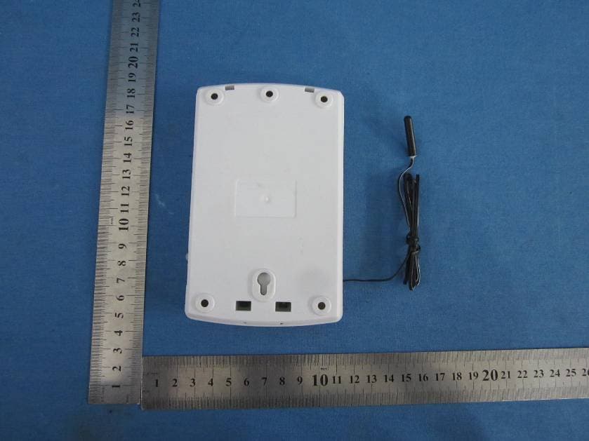
DI2AAHZT3A
May 29, 2013Wireless Thermostat Controller
Equipment Class
DXX - Part 15 Low Power Communication Device Transmitter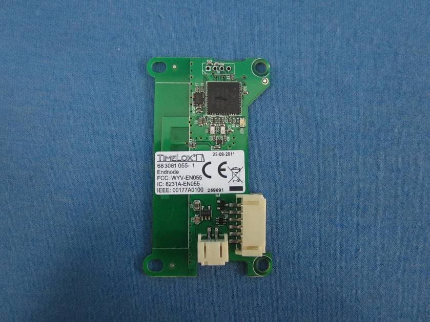
DI2AAHZT21
May 27, 2013Wireless Thermostat
Equipment Class
DXX - Part 15 Low Power Communication Device Transmitter
DI2-TDL6192
Oct 07, 2012US SMART PLUG
Equipment Class
DTS - Digital Transmission System