DI2RCTHLThermostatic Hi/Lo Remote control (Transmitter)
Computime Limited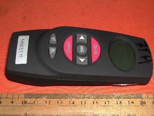
Click to zoom
Application Details
- Equipment Class
- DSC - Part 15 Security/Remote Control Transmitter
- Date of Grant
- Sep 19, 2002
- Application Purpose
- Original Equipment
- Date of Application
- Sep 19, 2002
- Equipment Note
- Thermostatic Hi/Lo Remote control (Transmitter)
- Frequency Range
- 350.00000000 - 350.00000000
- Company
- Computime Limited
- Country
- Hong Kong
Documents & Files
Document Text
Text extracted from the exhibit documents filed with the FCC. Open a document above to read the original.
Users Manual
RCTHL Thermostatic HI/LO Remote Control INSTALLATION AND OPERATING INSTRUCTIONS This hi/lo remote control system provides a safe, reliable, and user-friendly remote control to power up to a 6 VDC servo motor or solenoid gas valve system (Maxitrol Gas Valve). Always check the appliance home owner’s manual for additional information, or warnings regarding accessory installation before connecting this remote control system. Carefully inspect the contents for shipping damage. If any parts are missing or damaged, immediately contact the dealer from whom you purchased the kit. Do not attempt to install any part of the kit unless all parts are in good condition. Please keep this manual for future reference. CONTENTS OF KIT DescriptionQty Transmitter1 Battery Alkaline AAA ( for Transmitter)3 Receiver (Assembly) consists of :1 Receiver Box Push Button-Black (Hi/On, Lo/Off) L-Bracket (Floor Mount) Battery Alkaline AA (for Receiver)4 Wall Cover Plate-Black1 Wall Cover Plate-White1 Push Button-White (Hi/On, Lo/Off)1 Screws (for Wall Cover Plate)2 Plug-In Wiring Assembly – 18" Inches1 Velcro (Loop and Hook)1 Wall Holster1 Wall Holster Screws2 Wall Anchor2 Installation Instructions1 Screws (for fireplace system control covers) 2 FEATURES/SPECIFICATIONS • Contemporary Ergonomic Style Transmitter with Large LCD Display • Backlit LCD Display • Battery Powered Transmitter and Receiver • Easy Access Front Battery Door • Pre-Programmed for Quick Installation • Low battery Indication • Child Proof Lockout • Over 4 million security codes • Thermal Shutdown and Out of Range Shutdown On Transmitter • Quick Disconnect Wiring Assembly • On/Off, Thermostatic, Timer, and 5-2 Day Thermostatic Programming Flexibility • Reset Button WARNING Important Safety Information • Read this manual thoroughly prior to installing, programming or operating this remote control. • This remote control system is designed for use with a 6 VDC servo motor or solenoid gas valve system (Maxitrol Gas Valve). • This remote control system requires three (3) "AAA" and four (4) "AA" alkaline batteries to power the transmitter and receiver. Wiring must conform to appliance requirements and building codes/ordinances as required by local and national code authorities having jurisdiction. • Do not short (or jumper) across the gas valve terminals to test the remote control installation. This could damage the unit and void the warranty. • This remote control system should only be used as described in this manual. Any other use is not recommended and will void the warranty. Due to the sensitive temperature monitoring components in the transmitter, it is necessary to allow the transmitter to stabilize to room temperature before accurate room temperatures are displayed. If the transmitter is activated from a severe cold condition, allow 15 minutes for accurate temperature readings to appear on the LCD. Turn appliance OFF and allow to cool before installing or servicing. DO NOT connect 110-120 VAC wiring to the milli-volt gas control valve. The remote operator must be installed exactly as outlined in these instructions. Read all instructions completely before attempting installation. Follow instructions carefully during installation. Any modification of components will void the warranty and may cause a fire hazard. Low battery power in the transmitter or receiver can affect the operation of the remote control in the AUTO mode. In some cases the unit may not cycle off when the target temperature is reached. INSTALLATIONS Remote Receiver: The remote receiver may be wall mounted or installed in the appliance per the appliance homeowner’s manual. Refer to the Homeowner’s Manual for special installation instructions.If wall mounted, the remote receiver must be installed in a junction box with cover plate provided. Failure to follow the installation instructions found in the appropriate Homeowner’s Manual will void the warranty and may cause a fire hazard. Installing Batteries: The remote receiver uses four (4) "AA"- size batteries. To install batteries, 1. Remove the push buttons by gently pulling straight out. 2. Use your thumb and index finger to gently pull down the L-bracket. 3. Open the battery door by pressing the two tabs located on the door. 4. Install the batteries as indicated in the receiver cover. 5. Close the battery door until the door tab snaps in place. 6. To install the receiver into a wall junction box, install the receiver with the screws provided. 7. If you decided to install the receiver into the appliance, reinstall the L-bracket. 8. Gently, install the push buttons back to the receiver stem. 9. The batteries should be replaced at least once every 6 months or when the battery indicator flashes. Installing Wire: This system comes with an 18 inch pre-assembled wire assembly. Insert the white terminal to the back of the receiver. The terminal wire block can only be installed one way. Do not force the termi- nal plug onto the receiver. Follow the homeowner’s manual for connecting the 1/4",3/16", and two (2) 1/8" female spade terminals to the valve. For applications longer than 18 inches, use 18 gauge wire, 105ºC rated, with no splices. Connect to the the 1/4", 3/16", and two (2) 1/8" female spade wiring terminals. Wire can be no longer than 20 feet. Make sure that the wires do not contact the appliances any place other than at the terminals. Exposure to temperatures higher than 105C (250ºF) may cause the receiver to malfunction or fire hazard. Setting Privacy Security Code on Transmitter and Receiver The remote receiver and transmitter security codes are preset at the factory. A privacy code can be set into the system to prevent accidental operation by other transmitters in the vicinity using the following procedure: 1. Press the two push buttons on the receiver simultaneously and then press ON/HI button on the transmitter once. 2. The receiver LED will blink twice and the security code is now set. 3. The system is ready to operate. Reset B…
Text truncated - open the document above for the full version.
Block Diagram
3XAAA BATTERY VOLTAGE REGULATOR CIRCUIT LOW BATTERY CIRCUIT LCD MCU Temperature SENSOR 350MHz sine wave oscillation CIRCUIT 20 bit address generationRF control signal key input
External Photos
Test Setup FCC ID : DI2RCTHL External Photo -front External Photo - rear
ID Label/Location Info
FCC ID : DI2RCTHL IC : 1700A-RCTHL This device complies with Part 15 of the FCC Rules. Operation is subject to the following two conditions: 1) This device may not cause harmful interference, and 2) This device must accept any interference received, including interference that may cause undersired operation. Model : RCTHL MADE IN CHINA
Internal Photos
Test Setup FCC ID : DI2RCTHL Internal Photo - 1 Internal Photo - 2 Test Setup FCC ID : DI2RCTHL Internal Photo – 3 Internal Photo - 4
Operational Description
Critical Component of MHN3TH(TX) Component Part Number Description MCU MSM64P164 U2 Control all activities of the unit, detect and display temperature, LCD LCD1 Display time temperature and other information OSCILLATOR Y1 Supply MCU clock timing Touch key RST0 Reset MCU LED LED1/2 Back light PT2240 U3 Generate 20 bit address and encode the RF signal 103AT TH1 Detect the temperature RF transistor MMBTH10 Q1 Generate oscillation of RF frequency 350MHz and as modulator
Test Report
Print_02 (512x316x256 bmp)
Test Report
• The test results reported in this test report shall refer only to the sample actually tested and shall not refer or be deemed to refer to bulk from which such a sample may be said to have been obtained. • This report shall not be reproduced except in full without prior authorization from Intertek Testing Services Hong Kong Limited. • For Terms And Conditions of the services, it can be provided upon request. • The evaluation data of the report will be kept for 3 years from the date of issuance. Intertek Testing Services Hong Kong Ltd. 2/F., Garment Centre, 576 Castle Peak Road, Kowloon, Hong Kong. Tel: (852) 2173 8888 Fax: (852) 2785 5487 Computime Ltd. Application For Certification (FCC ID: DI2RCTHL) Transmitter WO# 0209021 DL/Sandy September 11, 2002 INTERTEK TESTING SERVICES FCC ID: DI2RCTHL i LIST OF EXHIBITS INTRODUCTION EXHIBIT 1: General Description EXHIBIT 2: System Test Configuration EXHIBIT 3: Emission Results EXHIBIT 4: Equipment Photographs EXHIBIT 5: Product Labelling EXHIBIT 6: Technical Specifications EXHIBIT 7: Instruction Manual EXHIBIT 8: Miscellaneous Information INTERTEK TESTING SERVICES FCC ID: DI2RCTHL ii MEASUREMENT/TECHNICAL REPORT Computime Ltd. - MODEL: Ambient RCTHL FCC ID: DI2RCTHL September 11, 2002 This report concerns (check one:) Original Grant X Class II Change Equipment Type: Low Power Transmitter (example: computer, printer, modem, etc.) Deferred grant requested per 47 CFR 0.457(d)(1)(ii)? Yes No X If yes, defer until: date Company Name agrees to notify the Commission by: date of the intended date of announcement of the product so that the grant can be issued on that date. Transition Rules Request per 15.37? Yes No X If no, assumed Part 15, Subpart C for intentional radiator - the new 47 CFR [12-18-01 Edition] provision. Report prepared by: Derek Leung Intertek Testing Services 2/F., Garment Center, 576, Castle Peak Road, HONG KONG. Phone: 852-2173-8504 Fax: 852-2371-0521 INTERTEK TESTING SERVICES FCC ID: DI2RCTHL iii Table of Contents 1.0 General Description............................................................................................................2 1.1 Product Description ...........................................................................................................2 1.2 Related Submittal(s) Grants ...............................................................................................2 1.3 Test Methodology ..............................................................................................................3 1.4 Test Facility.......................................................................................................................3 2.0 System Test Configuration .................................................................................................5 2.1 Justification........................................................................................................................5 2.2 EUT Exercising Software ..................................................................................................5 2.3 Special Accessories............................................................................................................5 2.4 Equipment Modification ....................................................................................................6 2.5 Measurement Uncertainty..................................................................................................6 2.6 Support Equipment List and Description............................................................................6 3.0 Emission Results ..................................................................................................................8 3.1 Field Strength Calculation..................................................................................................9 3.2 Radiated Emission Configuration Photograph ..................................................................11 3.3 Radiated Emission Data ...................................................................................................12 4.0 Equipment Photographs ...................................................................................................15 5.0 Product Labelling ..............................................................................................................17 6.0 Technical Specifications ....................................................................................................19 7.0 Instruction Manual ...........................................................................................................21 8.0 Miscellaneous Information ...............................................................................................23 8.1 Measured Bandwidth .......................................................................................................24 8.2 Discussion of Pulse Desensitization .................................................................................25 8.3 Calculation of Average Factor..........................................................................................26 8.4 Emissions Test Procedures...............................................................................................27 INTERTEK TESTING SERVICES FCC ID: DI2RCTHL iv List of attached file Exhibit type File Description filename Test Report Test Report report.pdf Operation Description Technical Description descri.pdf Test Setup Photo Radiated Emission radiated photos.doc Test Report Bandwidth Plot bw.pdf External Photo External Photo external photos.doc Internal Photo Internal Photo internal photos.doc Block Diagram Block Diagram block.pdf Schematics Circuit Diagram circuit.pdf ID Label/Location Label Artwork and Location label.pdf User Manual User Manual manual.pdf Timing Diagram Timing Diagram timing.pdf INTERTEK TESTING SERVICES FCC ID: DI2RCTHL 1 EXHIBIT 1 GENERAL DESCRIPTION INTERTEK TESTING SERVICES FCC ID: DI2RCTHL 2 1.0 General Description1.0 General …
Text truncated - open the document above for the full version.
Test Setup Photos
Test Setup FCC ID : DI2RCTHL Radiated -front Radiated - rear
Contact Information
Applicant
Philip Chung(Reliability Manager)
Technical Contact
Intertek Testing Services Hong Kong Ltd.Derek Leung
[email protected](852)2173-8504
2/F., Garment Centre, · Kowloon · Hong Kong
Non-Technical Contact
Intertek Testing Services Hong Kong Ltd.Derek Leung
[email protected](852)2173-8504
Test Firm
Intertek Testing Services Hong KongBilly Chow
Technical Specifications
| # | Rule Parts | Frequency Range | Power Output |
|---|---|---|---|
| 1 | 15.231(e) | 350 MHz - 350 MHz | - |
Other Applications from Computime Limited

DI2RCSTA-TX
Dec 04, 2014Transmitter
Equipment Class
DSC - Part 15 Security/Remote Control Transmitter
DI2RCST-RX
Dec 04, 2014Receiver
Equipment Class
CYY - Communications Receiver used w/Pt 15 Transmitter
DI2AAHZT3A
May 29, 2013Wireless Thermostat Controller
Equipment Class
DXX - Part 15 Low Power Communication Device Transmitter
DI2AAHZT21
May 27, 2013Wireless Thermostat
Equipment Class
DXX - Part 15 Low Power Communication Device Transmitter
DI2-TDL6192
Oct 07, 2012US SMART PLUG
Equipment Class
DTS - Digital Transmission System