DI2RSReceiver
Computime Limited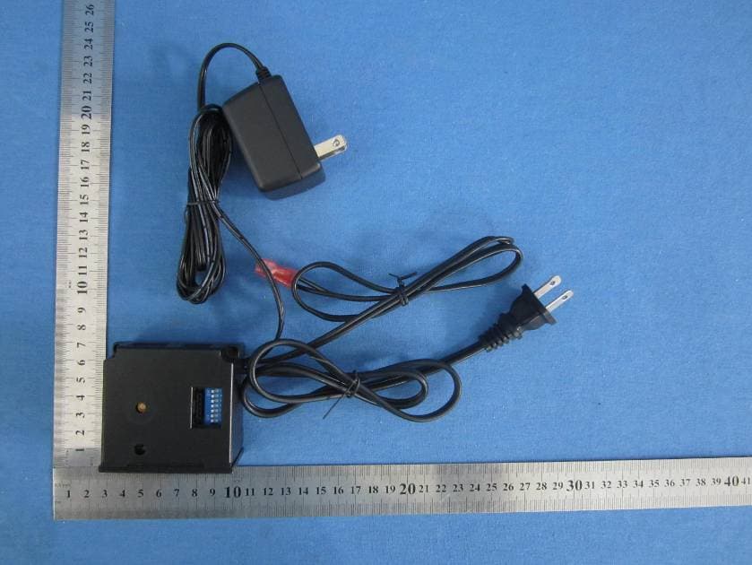
Click to zoom
Application Details
- Equipment Class
- CYY - Communications Receiver used w/Pt 15 Transmitter
- Date of Grant
- Sep 25, 2012
- Application Purpose
- Original Equipment
- Date of Application
- Sep 25, 2012
- Equipment Note
- Receiver
- Frequency Range
- 350.47700000 - 350.47700000
- Company
- Computime Limited
- Country
- Hong Kong
Documents & Files
Document Text
Text extracted from the exhibit documents filed with the FCC. Open a document above to read the original.
Users Manual
50D0111 RCSITEA Installation & Operating Manual Rel 1.0 April 2009 Page 1 of 10 Ambient Technologies A Division Of Monessen Hearth Systems RCSITEA Thermostatic On/Off, Flame Height Adjustment and Blower Remote Control– 120VAC INSTALLATION AND OPERATING INSTRUCTIONS CAUTION: The RCSITEA is only certified to be used on vented heater rated equipment. This remote control system provides a safe, reliable and user-friendly remote control for millivolt valve gas appliances, blower speed and flame height adjustment. The system can be manually or thermostatically turned on and off with the transmitter. Always check the appliance home owner’s manual for additional information, or warnings regarding accessory installation before connecting this remote control system. Carefully inspect the contents for shipping damage. If any parts are missing or damaged, immediately contact the dealer from whom you purchased the kit or Ambient Technologies Technical Support at 1 800 398 6195. Do not attempt to install any part of the kit unless all parts are in good condition. Please keep this booklet for future reference. Please check the gas type of the unit to match the current CONTENTS OF KIT Description Qty Transmitter 1 Battery Alkaline AAA (for Transmitter) 3 Receiver (Assembly) consists of : 1 Receiver Box AC Adaptor for Receiver SIT Stepper Motor 1 Slide Button-Black (On/RS/Off) 1 Wall Cover Plate-Black 1 Wire Nuts 2 Plug-In Wiring Assembly for SIT mV Valve– 22” Inches 1 Plug-In Wiring Assembly for SIT Hi/Lo Regulator – 10” Inches 1 Velcro (Loop and Hook) 1 Installation Instructions 1 #8 Screw for sheet metal, Black 2 FEATURES/SPECIFICATIONS • Easy Access Thermostatic Control • Battery Powered Transmitter • Low battery Indication for Transmitter • Compact 120 VAC Adapter with 30” Wire • Three Speed Control for Blower with Blower Type Selection • Three Flame Height Settings • Programmable Timer to Turn Blower on and Off • Child Proof Lock-out • 16 Security Codes • 6 hour Shut Down (Optional) on Receiver 50D0111 RCSITEA Installation & Operating Manual Rel 1.0 April 2009 Page 2 of 10 Ambient Technologies A Division Of Monessen Hearth Systems • Quick Disconnect Wiring Assembly • Reset Button for transmitter WARNING Important Safety Information • Read this manual thoroughly prior to installing, programming or operating any remote control. • This remote control system is designed for use with a millivolt gas valve system with blower. Do not use this remote control system on applications with voltages above 24 Volts AC/DC and 1 amp current. • This remote control system requires three (3) “AAA” alkaline batteries to power the transmitter. The receiver is powered by external AC Adapter. • Wiring must conform to appliance requirement and building codes/ordinances as required by local and national code authorities having jurisdiction. • Do not short (or jumper) across the gas valve terminals to test the remote control installation. This could damage the unit and void the warranty. • This remote control system should only be used as described in this manual. Any other use is not recommended and will void the warranty. NOTE Due to the sensitive temperature monitoring components in the transmitter, it is necessary to allow the transmitter to stabilize to room temperature before accurate room temperatures are displayed. If the transmitter is activated from a severe cold condition, allow 15 minutes for accurate temperature readings to appear on the LCD display. WARNING Turn appliance OFF and allow to cool before installing or servicing. DO NOT connect 110-120 VAC wiring to the milli-volt gas control valve. The remote operator must be installed exactly as outlined in these instructions. Read all instructions completely before attempting installation. Follow instructions carefully during installation. Any modification of components will void the warranty and may cause a fire hazard. WARNING Turn appliance OFF (at the appliance or remote receiver) if you are away from your house for an extended period of time. Never leave anything on top of the surface of the transmitter. INSTALLATIONS Remote Receiver: The remote receiver may be installed in the appliance per the appliance homeowner’s manual. Refer to the Homeowner’s Manual for special installation instructions. Failure to follow the installation instructions found in the appropriate Homeowner’s Manual will void the warranty and may cause a fire hazard. 50D0111 RCSITEA Installation & Operating Manual Rel 1.0 April 2009 Page 3 of 10 Ambient Technologies A Division Of Monessen Hearth Systems This system comes with an 22 inch two-wire assembly labled “FOR MILLVOLT VALVE ONLY, TP/TH” and an 10 inch four-wire assembly labeled “SIT VALVE ONLY”. Insert the white terminals into the back of the receiver. The terminal wire blocks can only be installed one way and do not force the terminal plugs into the receiver. Connect the wiring terminal two (2) ¼” female spade terminals to the appliance valve and four-pin connector to SIT valve. Refer to the appropriate Homeowner’s Manual for proper wiring connections to the appliance. Your appliance may have other options to connect wiring from receiver. For applications longer than 22 inches, use 18 gauge wire, 105ºC rated, with no splices. Connect to the two (2) 1/4“ female spade wiring terminals and wire can be no longer than 20 feet. WARNING Speed control module and thermal sensor must be removed before installing receiver and applying the AC power. Failure to do so may cause the part damage and void the warranty. Without removing the control module and thermal sensor, they and RCSTEB both will try to operate the blower at the same and may cause unexpected blower operation or damage. Before connecting the blower with the receiver, always DISCONNECT SPEED CONTROL MODULE AND THERMAL SENSOR from your fireplace if they exist as displayed in following diagram: Connect the 30” long 18AWG wires labled “120VAC FAN ONLY” between receiver and blower as…
Text truncated - open the document above for the full version.
Cover Letter(s)
Computime Limited 17/F, Great Eagle Centre, 23 Harbour Road, Wanchai, Hong Kong DATE :2012-09-20 Nemko Canada Inc 303 River Road Ottawa, Ontario, Canada K1V 1H2 Attn: Director of Certification Authority to Act as Agent On our behalf, I appoint Hans.Hu of Global United Technology Services Co., Ltd. 2nd Floor, Block No.2, Laodong Industrial Zone, Xixiang Road Baoan District Shenzhen Guangdong to act as our agent in the preparation of this application for equipment certification. I certify that submitted documents properly describe the device or system for which equipment certification is sought. I also certify that each unit manufactured, imported or marketed, as defined in the Federal Communications Commission’s regulations will have affixed to it a label identical to that submitted for approval with this application. For instances where our authorized agent signs the application for certification on our behalf, I acknowledge that all responsibility for complying with the terms and conditions for certification, as specified by Nemko Canada Inc, still resides with Computime Limited and 17/F, Great Eagle Centre, 23 Harbour Road, Wanchai, Hong Kong Dated this / Day of 09/20/2012 / Agency agreement expiration date: 09/20/2013 By: Philip Chung Signature Printed Title: Reliability Manager On behalf of : Computime Limited Telephone: 852 2660 0464
Cover Letter(s)
Computime Limited 17/F, Great Eagle Centre, 23 Harbour Road, Wanchai, Hong Kong 2012-09-20 Equipment Autorisation Division Federal Communications Commission 7435 Oakland Mills Road Columbia, MD 21046 FCC ID: DI2RS Product Name: Receiver Request for Confidentiality Pursuant to Sections 0.457 and 0.459 of the commissions rules, we hereby request that the following documents be held confidential: • Schematics • Block diagram • Operational Description These materials contain trade secrets and proprietary information and are not customarily released to the public. The public disclosure of this information might be harmful to the company and provide unjustified benefits to our competitors. Dated this 09/20/2012 By: Philip Chung Signature Printed Title: Reliability Manager On behalf of : Computime Limited Telephone: 852 2660 0464
ID Label/Location Info
Label Location
Test Report
Global United Technology Services Co., Ltd. Report No: GTSE12050040802 Authorized Signature: Robinson Lo Laboratory Manager This report details the results of the testing carried out on one sample. The results contained in this test report do not relate to other samples of the same product and does not permit the use of the GTS product certification mark. The manufacturer should ensure that all products in series production are in conformity with the product sample detailed in this report. This report may only be reproduced and distributed in full. If the product in this report is used in any configuration other than that detailed in the report, the manufacturer must ensure the new system complies with all relevant standards. Any mention of GTS International Electrical Approvals or testing done by GTS International Electrical Approvals in connection with, distribution or use of the product described in this report must be approved by GTS International Electrical Approvals in writing. This document cannot be reproduced except in full, without prior written approval of the Company. Any unauthorized alteration, forgery or falsification of the content or appearance of this document is unlawful and offenders may be prosecuted to the fullest extent of the law. Unless otherwise stated the results shown in this test report refer only to the sample(s) tested and such sample(s) are retained for 90 days only.” 1 Cover Page TEST REPORT Applicant: Computime Limited Address of Applicant: 17/F, Great Eagle Centre, 23 Harbour Road, Wanchai, Hong Kong Equipment Under Test (EUT) Product Name: Receiver Model No.: RS FCC ID: DI2RS Applicable standards: FCC CFR Title 47 Part 15 Subpart B:2010 Date of sample receipt: Jul. 14, 2012 Date of Test: Jul. 22-September 19, 2012 Date of report issued: September 20, 2012 Test Result : PASS * * In the configuration tested, the EUT complied with the standards specified above. Report No: GTSE12050040802 Global United Technology Services Co., Ltd. Project No.: GTSE120500408RF 2nd Floor, Block No.2, Laodong Industrial Zone, Xixiang Road Baoan District, Shenzhen, China 518102 Telephone: +86 (0) 755 2779 8480 Fax: +86 (0) 755 2779 8960 Page 2 of 28 2 Version Version No. Date Description 00 September 20, 2012 Original Prepared by: Date: September 20, 2012 Project Engineer Reviewed by: Date: September 20, 2012 Reviewer Report No: GTSE12050040802 Global United Technology Services Co., Ltd. Project No.: GTSE120500408RF 2nd Floor, Block No.2, Laodong Industrial Zone, Xixiang Road Baoan District, Shenzhen, China 518102 Telephone: +86 (0) 755 2779 8480 Fax: +86 (0) 755 2779 8960 Page 3 of 28 3 Contents Page 1 COVER PAGE.........................................................................................................................................................1 2 VERSION..................................................................................................................................................................2 3 CONTENTS..............................................................................................................................................................3 4 TEST SUMMARY....................................................................................................................................................4 5 GENERAL INFORMATION...................................................................................................................................5 5.1 CLIENT INFORMATION....................................................................................................................................... 5 5.2 GENERAL DESCRIPTION OF E.U.T................................................................................................................... 5 5.3 TEST MODE....................................................................................................................................................... 5 5.4 TEST FACILITY................................................................................................................................................... 5 5.5 TEST LOCATION................................................................................................................................................ 6 5.6 DESCRIPTION OF SUPPORT UNITS................................................................................................................... 6 5.7 DEVIATION FROM STANDARDS.......................................................................................................................... 6 5.8 ABNORMALITIES FROM STANDARD CONDITIONS.............................................................................................. 6 5.9 OTHER INFORMATION REQUESTED BY THE CUSTOMER.................................................................................. 6 6 TEST INSTRUMENTS LIST..................................................................................................................................7 7 TEST RESULTS AND MEASUREMENT DATA................................................................................................8 7.1 CONDUCTED EMISSIONS................................................................................................................................... 8 7.2 RADIATED EMISSION....................................................................................................................................... 11 8 TEST SETUP PHOTO..........................................................................................................................................17 9 EUT CONSTRUCTIONAL DETAILS.................................................................................................................19 Report No: GTSE1205040802 Global United Technology Services Co., Ltd. Project No.: GTSE120500408RF 2nd Floor, Block No.2, Laodong Industrial Zone, Xixiang Road Baoan District, Shenzhen, China 518102 Telephone: +86 (0) 755…
Text truncated - open the document above for the full version.
Test Setup Photos
Radiated Emission Conducted Emission
Contact Information
Applicant
Philip Chung(Reliability Manager)
Technical Contact
Global United Technology Services Co., Ltd.Hans Hu
[email protected]+86-0755-27798480
2nd Floor, Block No.2, Laodong Industrial Zone · Shenzhen · China
Test Firm
Global United Technology Service Co., LtdRobinson Lo
Technical Specifications
| # | Rule Parts | Frequency Range | Power Output |
|---|---|---|---|
| 1 | 15B | 350.477 MHz - 350.477 MHz | - |
Other Applications from Computime Limited

DI2RCSTA-TX
Dec 04, 2014Transmitter
Equipment Class
DSC - Part 15 Security/Remote Control Transmitter
DI2RCST-RX
Dec 04, 2014Receiver
Equipment Class
CYY - Communications Receiver used w/Pt 15 Transmitter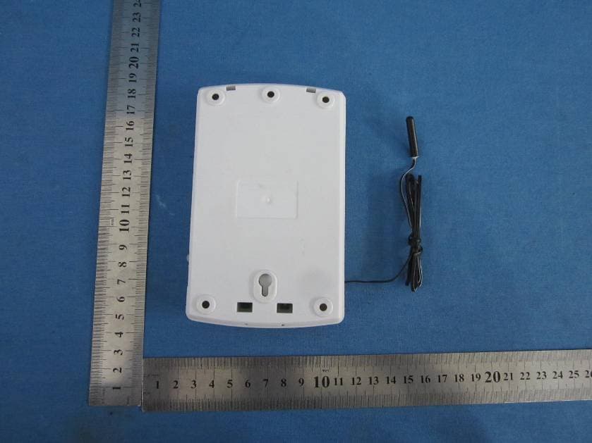
DI2AAHZT3A
May 29, 2013Wireless Thermostat Controller
Equipment Class
DXX - Part 15 Low Power Communication Device Transmitter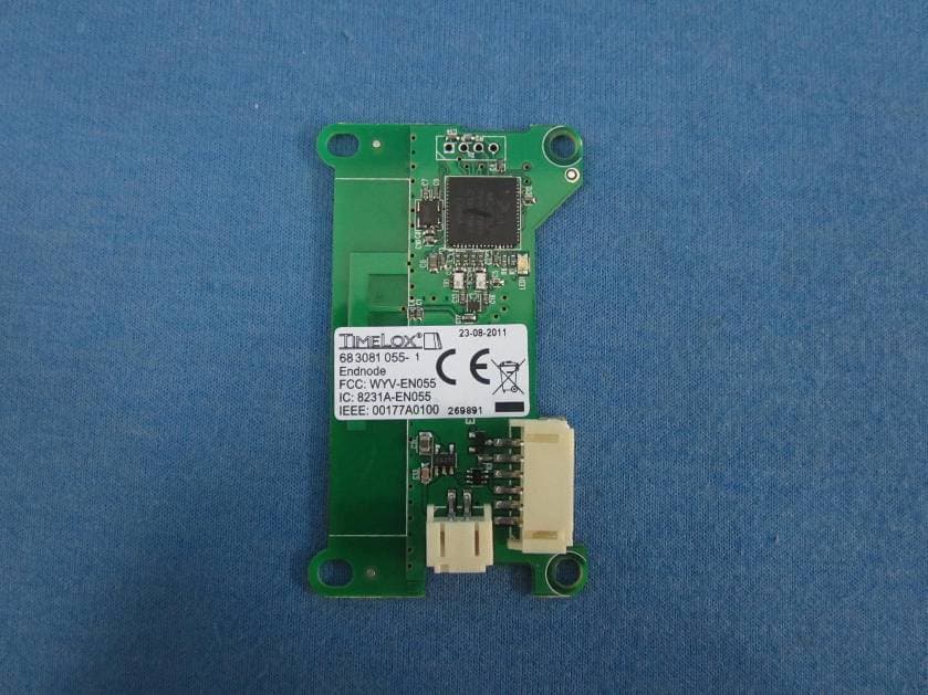
DI2AAHZT21
May 27, 2013Wireless Thermostat
Equipment Class
DXX - Part 15 Low Power Communication Device Transmitter
DI2-TDL6192
Oct 07, 2012US SMART PLUG
Equipment Class
DTS - Digital Transmission System