DK4CT900900 MHz Cordless Telephone
GVC Corporation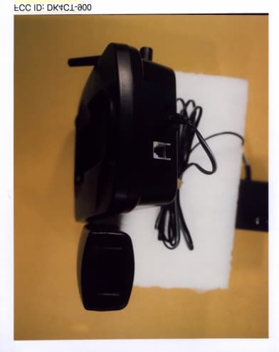
Click to zoom
Application Details
- Equipment Class
- ETS - Part 15 Cordless Telephone System
- Date of Grant
- Jul 18, 1999
- Application Purpose
- Original Equipment
- Date of Application
- Apr 21, 1999
- Equipment Note
- 900 MHz Cordless Telephone
- Frequency Range
- 926.02500000 - 927.92500000
- Company
- GVC Corporation
- Country
- Taiwan
Documents & Files
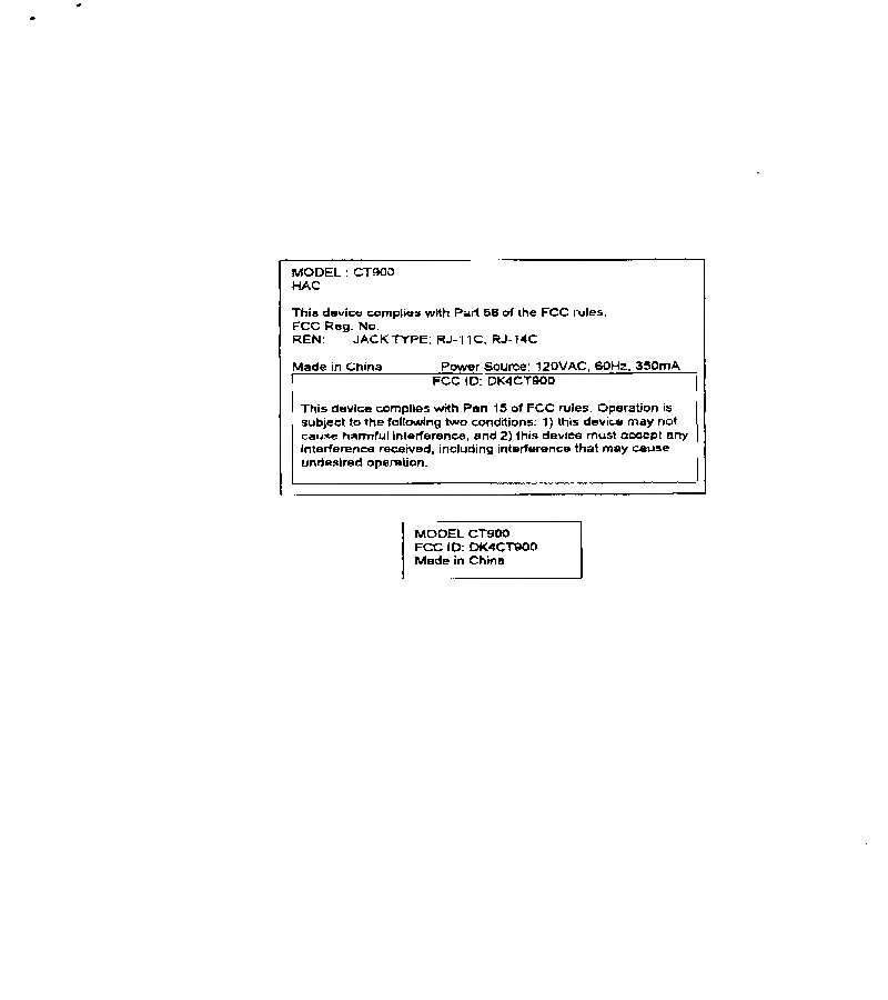
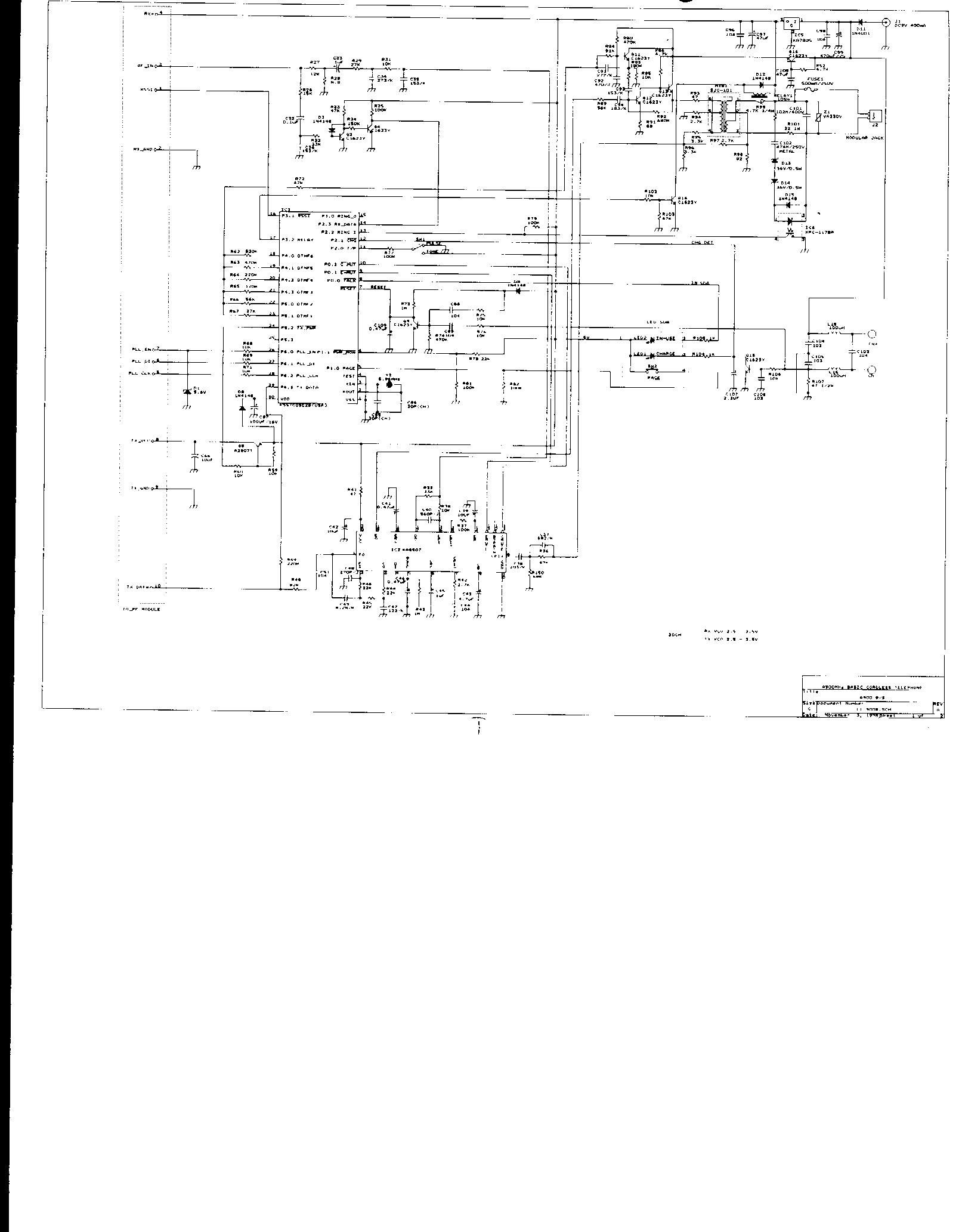
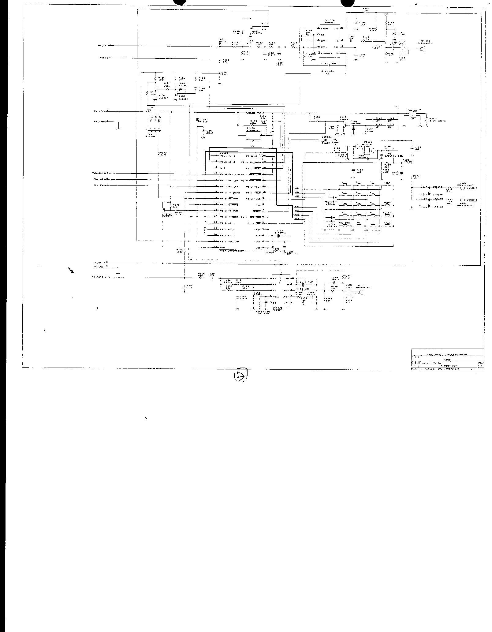
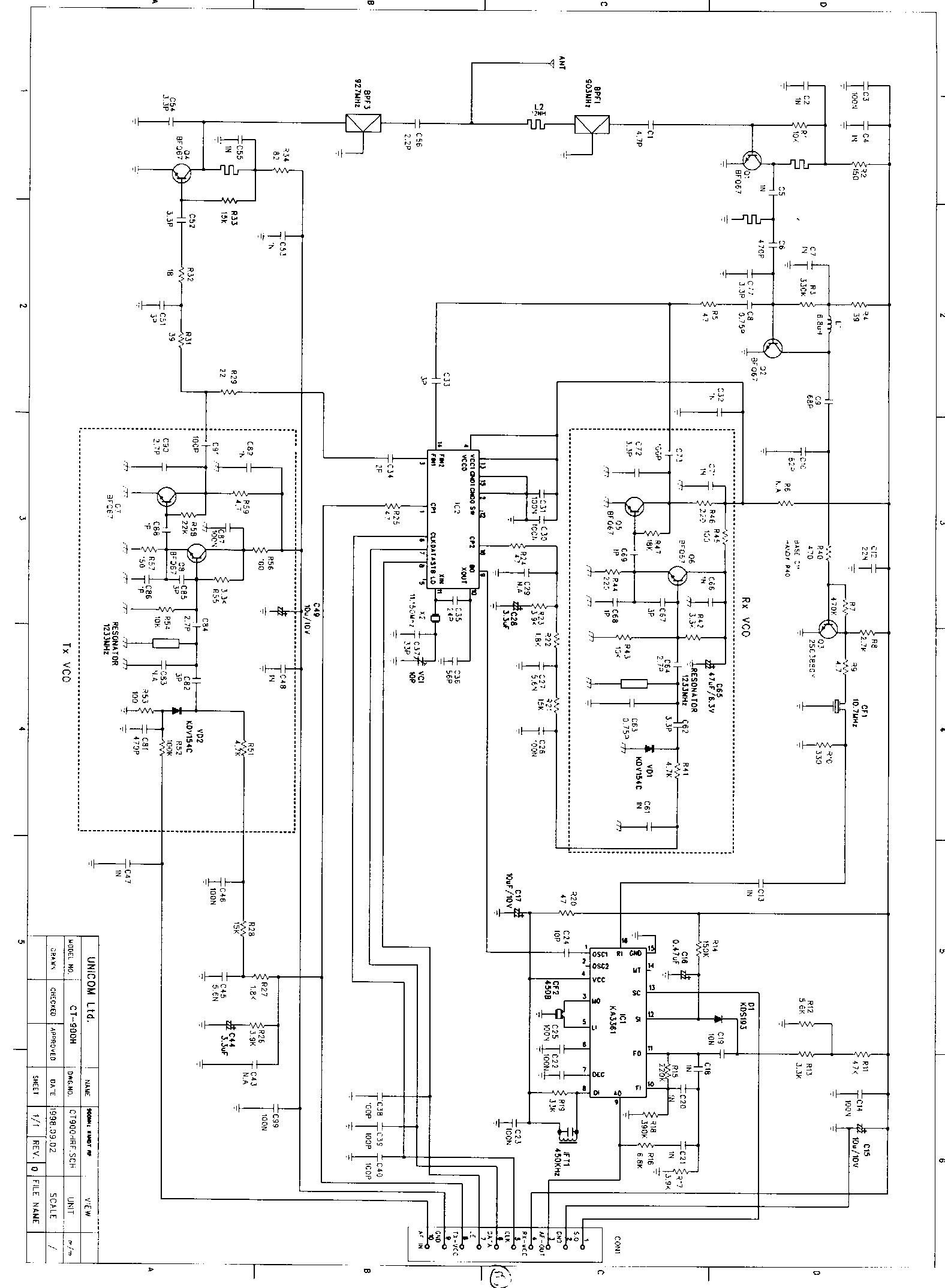
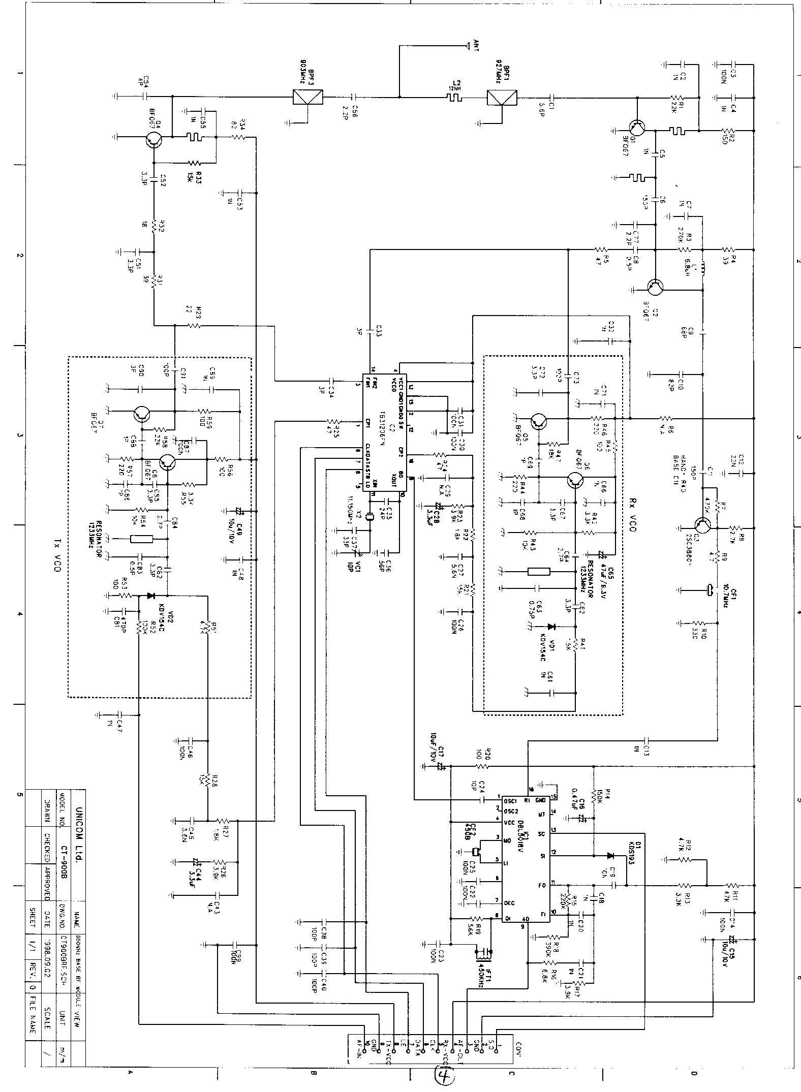
Document Text
Text extracted from the exhibit documents filed with the FCC. Open a document above to read the original.
Test Report
i Intertek Testing Services APPLICATION FOR FCC CERTIFICATION GVC Corporation 900 MHz Cordless Telephone Model: CT-900 FCC ID: DK4CT-900 Report # J98036684 Number of Pages: 27 Date of Report: March 5, 1999 This report shall not be reproduced except in full, without written approval of Intertek Testing Services. This report must not be used to claim product endorsement by NVLAP or any agency of the U.S. Government. The results contained in this report were derived from measurements performed on the identified test samples. Any implied performance of other samples on this report is dependent on the representative of the samples tested. FCC Part 15.249 Tx Cert, Ver 5/97k:\..\fcc\15249.cer Intertek Testing Services 1365 Adams Court, Menlo Park, CA 94025 GVC Corp., 900 MHz Cordless TelephoneDate of Test: Feb. 10, 1999 & March 1, 2, & 3, 1999 FCC ID: DK4CT-900 Report # J98036684FCC Part 15.249 Certification ii Table of Contents 0.0Summary of Test Results ...............................................1 1.0General Description...................................................2 1.1Product Description..............................................2 1.2Related Submittal(s) Grants........................................3 1.3Test Methodology...............................................3 1.4Test Facility....................................................3 2.0System Test Configuration .............................................4 2.1Justification....................................................4 2.2EUT Exercising Software..........................................4 2.3System Test Configuration.........................................5 2.3.1Support Equipment.........................................5 2.3.2Block Diagram of Test Setup.................................5 2.4Equipment Modification...........................................6 2.5Additions, deviations and exclusions from standards......................6 3.0Emission Results .....................................................7 3.1Field Strength Calculation..........................................8 3.3Radiated Emission Data...........................................9 3.5Conducted Emission Data.........................................20 4.0Out of Band Emission Plot ............................................21 5.0Antenna Requirement................................................26 6.0List of Exhibits.....................................................27 Intertek Testing Services 1365 Adams Court, Menlo Park, CA 94025 GVC Corp., 900 MHz Cordless TelephoneDate of Test: Feb. 10, 1999 & March 1, 2, & 3, 1999 FCC ID: DK4CT-900 Report # J98036684FCC Part 15.249 Certification 1 0.0Summary of Test Results GVC Corporation - Model No.: CT-900 FCC ID: DK4CT-900 TESTREFERENCERESULTS Radiated Emission15.249Complies Conducted Emission15.207Complies Antenna Requirement15.203Complies Test Engineer: Date: Cleveland Kwan Telco Mgr: Date: C.K. Li Intertek Testing Services 1365 Adams Court, Menlo Park, CA 94025 GVC Corp., 900 MHz Cordless TelephoneDate of Test: Feb. 10, 1999 & March 1, 2, & 3, 1999 FCC ID: DK4CT-900 Report # J98036684FCC Part 15.249 Certification 2 1.0General Description 1.1Product Description The GVC Corporation Model No.: CT-900 is a 900 MHz analog cordless telephone. Please refer to the attached technical description for details. Intertek Testing Services 1365 Adams Court, Menlo Park, CA 94025 GVC Corp., 900 MHz Cordless TelephoneDate of Test: Feb. 10, 1999 & March 1, 2, & 3, 1999 FCC ID: DK4CT-900 Report # J98036684FCC Part 15.249 Certification 3 1.2Related Submittal(s) Grants This is an Application for Certification of a low power transmitter. One transmitter is included in this Application. This specific report details the emission characteristics of transmitter. The FCC ID for the receiver assoicated with this transmitter is . The receivers are subject to the notification authorization process. A Notification report has been prepared for the receiver. 1.3Test Methodology Both AC mains line-conducted and radiated emission measurements were performed according to the procedures in ANSI C63.4 (1992). All measurements were performed in Open Area Test Sites. Preliminary scans were performed in the Open Area Test Sites only to determine worst case modes. For each scan, the procedure for maximizing emissions in Appendices D and E were followed. All Radiated tests were performed at an antenna to EUT distance of 3 meters, unless stated otherwise in the "Justification Section" of this Application. 1.4Test Facility The open area test site and conducted measurement facility used to collect the radiated data is Site 1. This test facility and site measurement data have been fully placed on file with the FCC and NVLAP accredited. Intertek Testing Services 1365 Adams Court, Menlo Park, CA 94025 GVC Corp., 900 MHz Cordless TelephoneDate of Test: Feb. 10, 1999 & March 1, 2, & 3, 1999 FCC ID: DK4CT-900 Report # J98036684FCC Part 15.249 Certification 4 2.0System Test Configuration 2.1Justification For emission testing, the equipment under test (EUT) was configured for testing in a typical fashion (as a customer would normally use it). During testing, all cables were manipulated to produce worst case emissions. For the measurements, the EUT is attached to a cardboard box (if necessary) and placed on the wooden turntable. If the EUT attaches to peripherals, they are connected and operational (as typical as possible). The EUT is wired to transmit full power without modulation. The signal is maximized through rotation and placement in the three orthogonal axes. The antenna height and polarization are varied during the search for maximum signal level. The antenna height is varied from 1 to 4 meters. Detector function is in peak mode. Radiated emissions are taken at three meters unless the signal level is too low for measurement at that distance. If necessary, a pre-amplifier is used and/or the test is conducted at a closer distance. All readings are extrapola…
Text truncated - open the document above for the full version.
Test Report
9 Dec 1998 18:58:42 3. FCC CFR 47, Pt. 15 3.1 FCC, PT 15 - AC LINE CONDUCTED GVC 900 MHz PHONE, M/N: CT-900 OPERATING MODE: TRANSMITTING HOT [X], NEUTRAL [ ] 115V 60Hz PEAKS FOUND ABOVE 32 dBuV PEAK #FREQ (MHz)AMPL (dBuV) 11.54535.6 23.27435.2 9 Dec 1998 18:58:42 3. FCC CFR 47, Pt. 15 3.1 FCC, PT 15 - AC LINE CONDUCTED GVC 900 MHz PHONE, M/N: CT-900 OPERATING MODE: TRANSMITTING HOT [ ], NEUTRAL [X] 115V 60Hz PEAKS FOUND ABOVE 32 dBuV PEAK #FREQ (MHz)AMPL (dBuV) 11.54535.6 23.27435.2 9 Dec 1998 18:40:30 3. FCC CFR 47, Pt. 15 3.1 FCC, PT 15 - AC LINE CONDUCTED GVC 900 MHz PHONE, M/N: CT-900 OPERATING MODE: CHARGING HOT [ ], NEUTRAL [X] 115V 60Hz PEAKS FOUND ABOVE 32 dBuV PEAK #FREQ (MHz)AMPL (dBuV) 1.786235.3 22.10735.8 25.89035.3 9 Dec 1998 18:53:03 3. FCC CFR 47, Pt. 15 3.1 FCC, PT 15 - AC LINE CONDUCTED GVC 900 MHz PHONE, M/N: CT-900 OPERATING MODE: CHARGING HOT [X], NEUTRAL [ ] 115V 60Hz PEAKS FOUND ABOVE 32 dBuV PEAK #FREQ (MHz)AMPL (dBuV) 1.735235.5 21.28535.3 25.86635.2
Contact Information
Applicant
T. C. Wu(Manager)
886 3 328-7799Fax: 886 3 397-7598
Technical Contact
Intertek Testing ServicesC.K. Li
(650) 463-2900
1365 Adams Court · Menlo Park, California · United States
Non-Technical Contact
GVC CorporationChris Park
(562) 404-2366
Test Firm
Intertek Testing Services NA Inc.John Quigley
Technical Specifications
| # | Rule Parts | Frequency Range | Power Output | Emission |
|---|---|---|---|---|
| 2 | - | 926.025 MHz - 927.925 MHz | - | N.A |
Other Applications from GVC Corporation
DK4MH9082
Oct 27, 1999DSS - Part 15 Spread Spectrum Transmitter
Equipment Class
DSS - Part 15 Spread Spectrum Transmitter
DK4GH2400
Oct 25, 1999Cordless Telephone
Equipment Class
DXT - Part 15 Low Power Transceiver, Rx Verified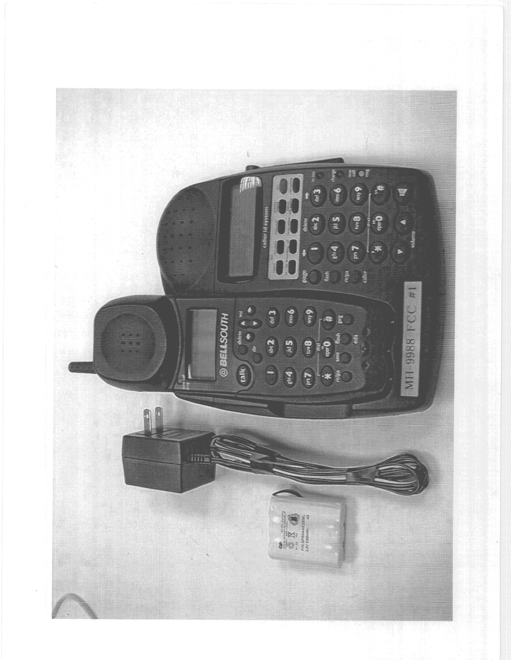
DK4MH9988BK
Oct 19, 1999Cordless Phone
Equipment Class
DSS - Part 15 Spread Spectrum Transmitter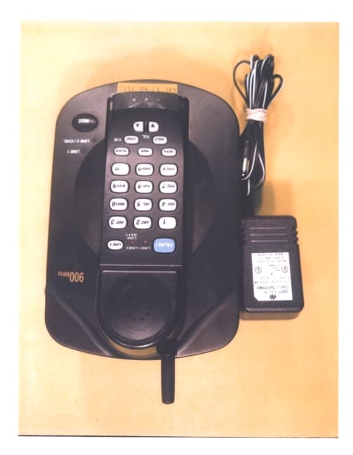
DK4CT910
Sep 30, 1999900 MHz Cordless Telephone
Equipment Class
ETS - Part 15 Cordless Telephone System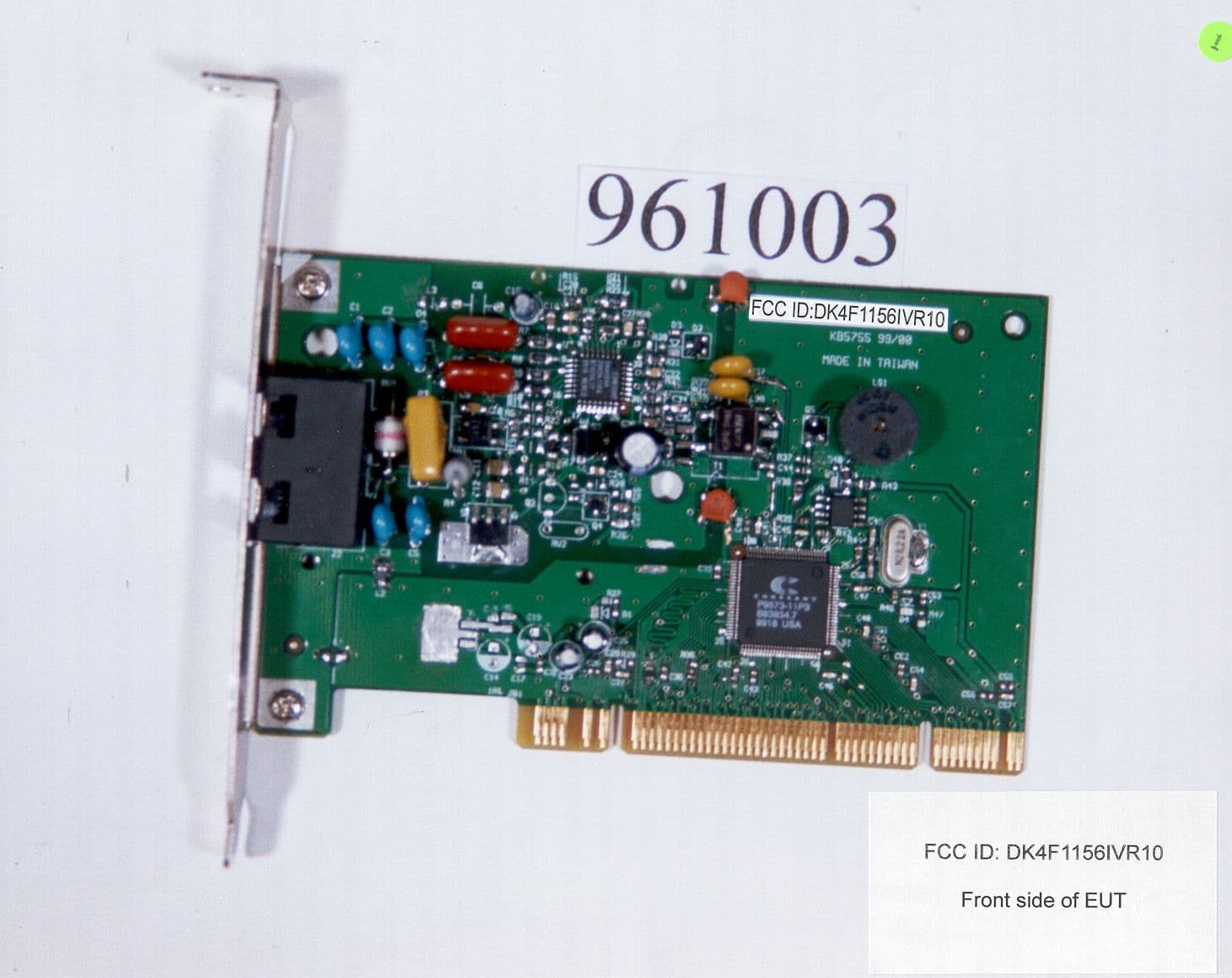
DK4F1156IVR10
Aug 10, 1999Data Fax Modem
Equipment Class
JBC - Part 15 Class B Computing Device/Personal Computer