DK4GH2400Cordless Telephone
GVC Corporation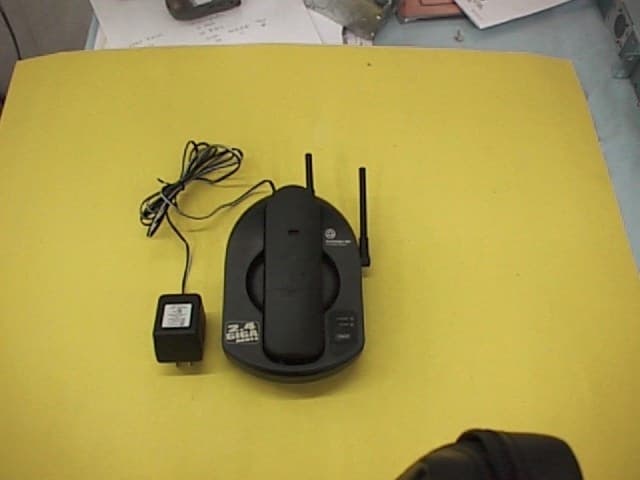
Click to zoom
Application Details
- Equipment Class
- DXT - Part 15 Low Power Transceiver, Rx Verified
- Date of Grant
- Oct 25, 1999
- Application Purpose
- Original Equipment
- Date of Application
- Jun 30, 1999
- Equipment Note
- Cordless Telephone
- Frequency Range
- 2462.10000000 - 2464.80000000
- Company
- GVC Corporation
- Country
- Taiwan
Documents & Files
Document Text
Text extracted from the exhibit documents filed with the FCC. Open a document above to read the original.
Users Manual
User’s Manual for Cordless Telephone GH2400 Fold open this manual for information about this telephone s installation. Please read the important Safety instructions included in your package. SOUTHWESTERN BELL FREEDOM PHONE 7475 North Glen Harbor Boulevard, Glendale, AZ 85307 GH2400 Printed in Korea IMPORTANT SAFETY INSTRUCTIONS BEFORE USING YOUR TELEPHONE EQUIPMENT, BASIC SAFETY PRECAUTIONS S H O U L D A LWAY S B E FOLLOWED TO REDUCE THE RISK OF FIRE, ELECTRIC SHOCK AND INJURY TO PERSONS, INCLUDING THE FOLLOWING: 1. Read and understand all instructions. 2. Follow all warnings and instructions marked on the product. 3. Unplug this product from the wall telephone jack and power outlet before cleaning. Do not use liquid cleaners or aerosol cleaners. Use damp cloth for cleaning. 4. Do not use this product near water; for example, near a bathtub, wash bowl, kitchen sink, laundry tub, swimming pool, or in a wet basement. 5. Do not place this product on an unstable cart, stand or table. The product may fall, causing serious damage to the product. 6. Slots or openings in the cabinet and the back and bottom are provided for ventilation, to protect it from overheating. These openings must not be blocked or covered. The openings should never be blocked by placing the product on the bed, or other similar surface. This product should never be placed near or over a radiator or heat register. This product should not be placed in a built-in installation unless proper ventilation is provided. 7. This product should be operated only from the type of power source indicated on the marking label. If you are not sure of the type of power supply to your home, consult your dealer or local power company. 8. Do not allow anything to rest on the power cord. Do not locate this productwhere the cord will be damaged by persons walking on it. 9. Do not overload wall outlets extension cords, as this can result in fire or electric shock. 10.Never push objects of any kind into this product through cabinet slots, as they may touch dangerous voltage points or short out parts. This could result in fire or electric shock. Never spill liquid of any kind on this product. 11.To reduce the risk of electric shock, do not disassemble this product. Instead, when some repair work is required, take the unit to a qualified technician. Opening or removing covers may expose you to dangerous voltages or other risks. Incorrect reassemble can cause electric shock when the appliance is subsequently used 12.Unplug this product from the wall outlet and refer servicing to qualified service personnel under the following conditions: a. When the power supply cord or plug is damaged or frayed. b. If liquid has been spilled into the product. c. If the product has been exposed to rain or water. d.If the product does not operate normally and proper operating instructions have been followed, adjust only those controls that are covered by the operating instructions. Improper adjustment of other controls may result in damage and will often require extensive work by a qualified technician to restore the product to normal operation. e. If the product has been dropped or cabinet has be damaged. f. If the product exhibits a distinct change in performance. 13. Avoid using telephone (other than a cordless type) during an electrical storm. There may be a remote risk of electrical shock from lightning. 14. Do not use the telephone to report a gas leak in the vicinity of the leak. SAVE THESE INSTRUCTIONS CAUTION: SAFETY INSTRUCTIONS FOR BATTERIES CAUTION : To reduce the risk of fire or personal injury, read and follow these instructions 1. Use only a Southwestern Bell Freedom Phone ?approved battery pack in the handset of your cordless 2. telephone. FOR HANDSET UNIT: 3N-600AAAL 3.6V 550mAh JALI Co., Ltd or GP60AAAS3BMX 3.6V 550mA GPI INTERNATIONAL LIMITED. 2. Do not dispose of the battery in a fire, as it may explode. Check with local codes for possible special disposal instructions. 3. Do not open or mutilate the battery. Released electrolyte is corrosive and may cause damage to the eyes and skin. It may be toxic if swallowed. 4. Exercise care in handing batteries in order not to short the battery with conducting materials such as rings, bracelets and keys. The battery or conduction material may overheat and cause burns. 5. Charge the battery (ies) provided with or identified for use with this product only in accordance with the instructions and limitations specified in this manual. 6. Observe proper polarity orientation between the Battery Pack and battery charger The RBRC TM Seal on the nickel-cadmium (N i -C D ) b a t t e r y i n d i c a t e s t h a t Southwestern Bell Freedom Phone Retail Sales is voluntarily participating in a program to collect and recycle these batteries at the end of their useful life, when taken out of service within the United States. Please call the RBRC TM , toll-free at 1-800-8- BATTERY or contact your local recycling center for information on where to return the spent battery. CONTAINS NICKEL-CADMIUM BATTERY.BATTERY MUST BE RECYCLED OR DISPOSED OF PROPERLY. BRC TM is a trademark of the Rechargeable Battery Recycling Corporation FCC WANTS YOU TO KNOW This equipment complies with Part 68 of the FCC rules. On the bottom of the base of this equipment is a label that contains, among other information, the FCC Registration Number, Ringer Equivalence number (REN) and the Universal Service Order Code (USOC), which is RJ-11C, for this equipment. You must, upon request, provide this information to your telephone company. The REN is useful to determine the quantity of devices you may connect to your telephone line and still have all of those devices ring when you telephone number is called. In most, but not all areas, the sum of the RENs of all devices connected to one line should not exceed five (5.0).To be certain of the number of devices you may connect to your line, as determined by the REN, you should contact your local telephone compan…
Text truncated - open the document above for the full version.
External Photos
EXTERNAL PHOTOGRAPHS
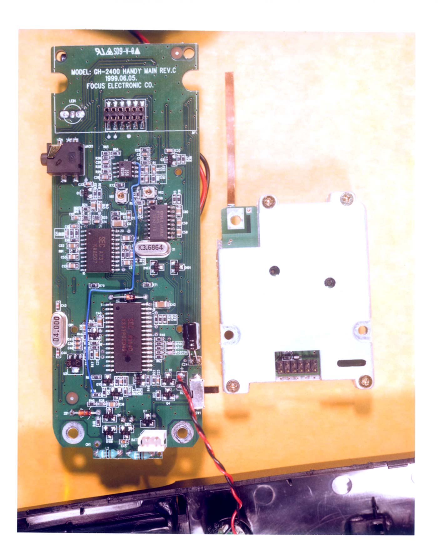
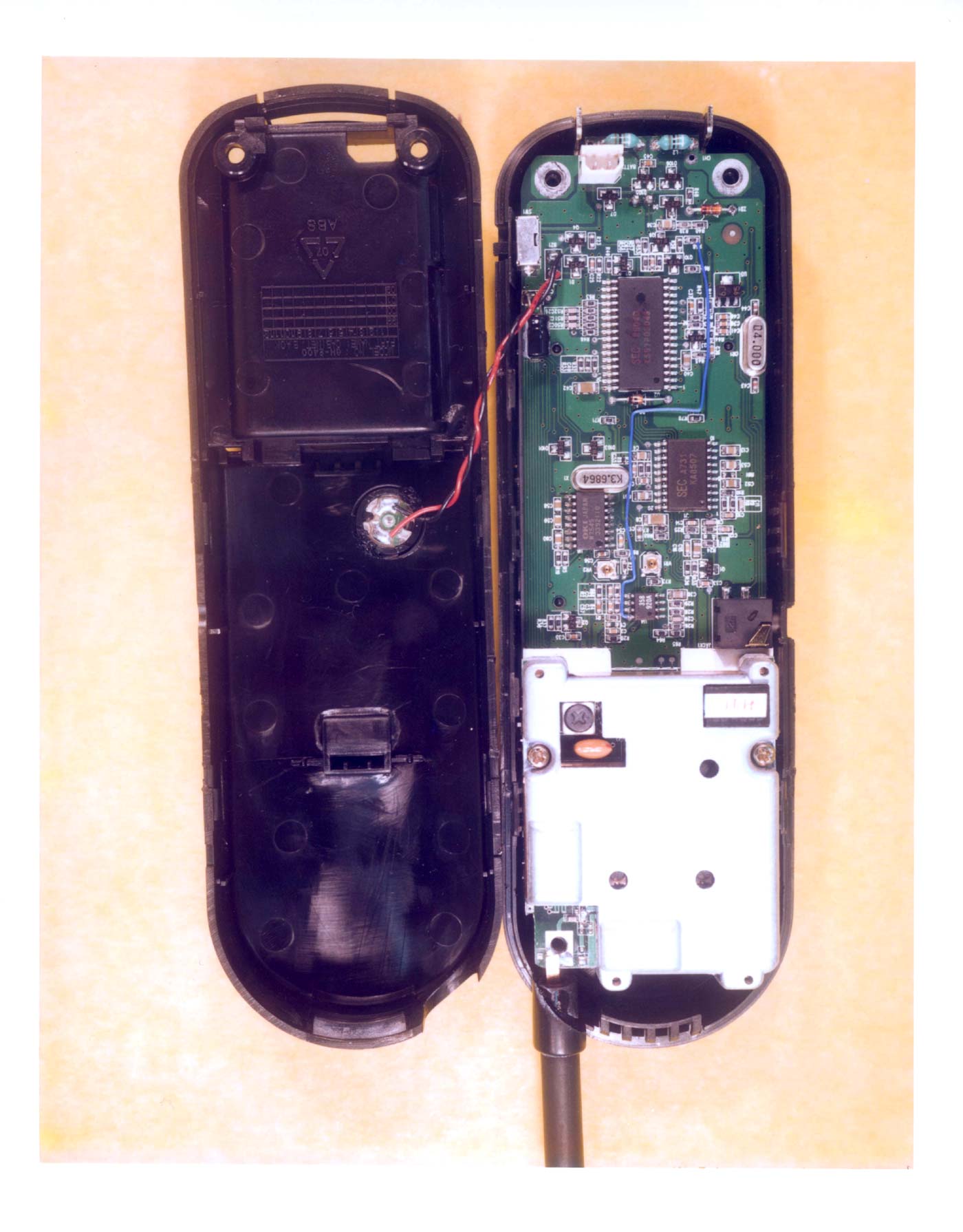
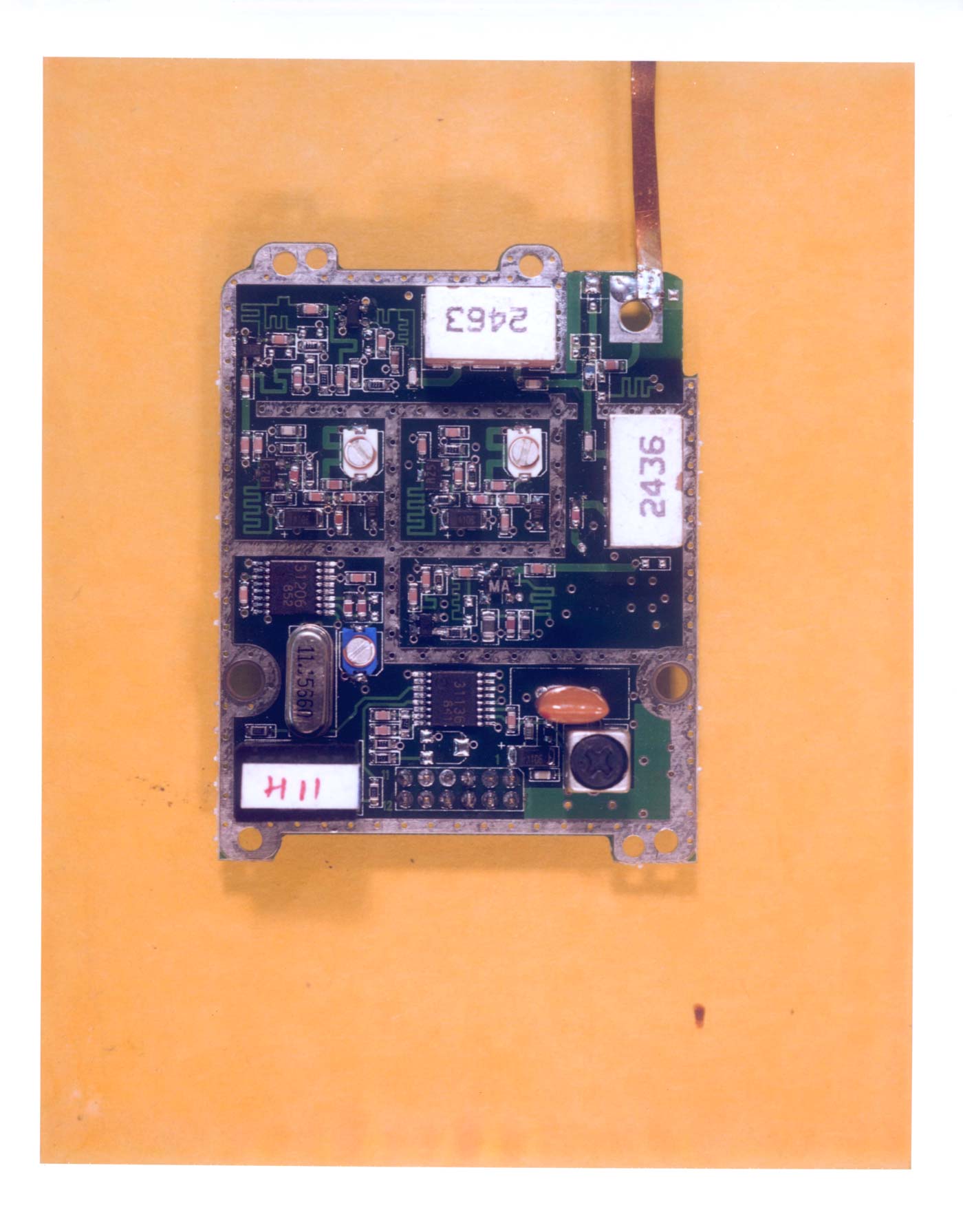
Internal Photos
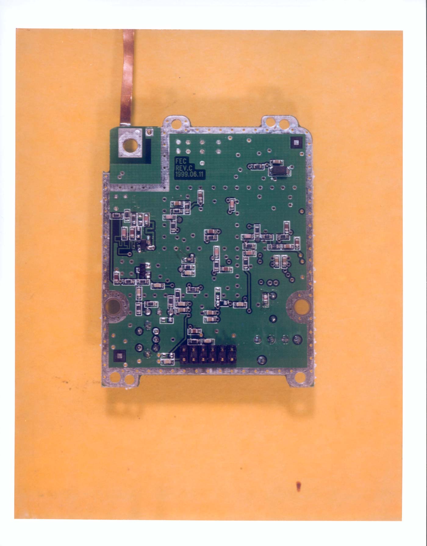
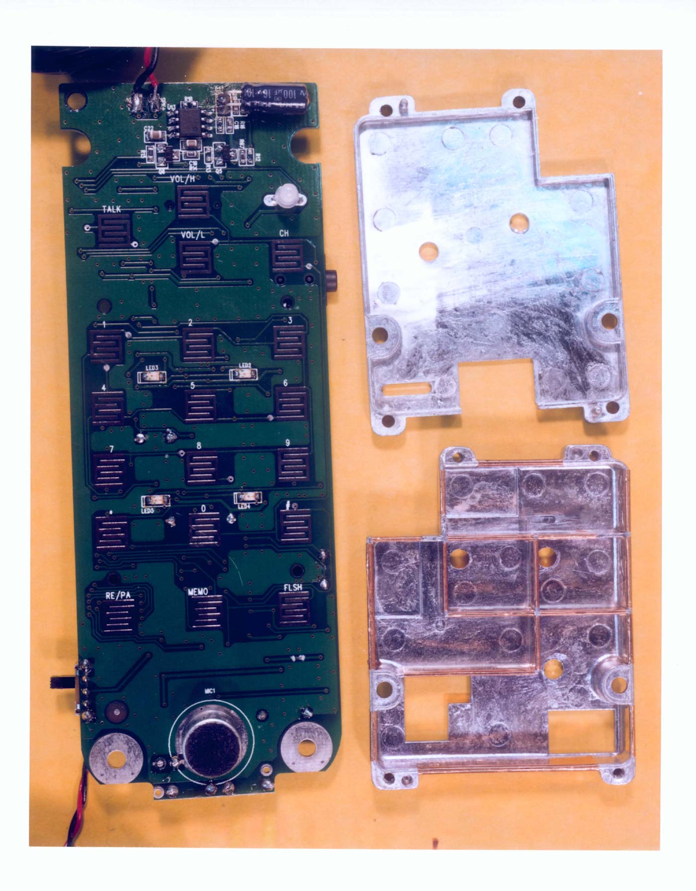
INTERNAL PHOTOGRAPHS
Operational Description
Circuit description for Base unit A Frequency modulation signal transmitted from the handset is received through a antenna of Base unit. And then delivered to the Filter U9 which eliminates harmonics of Rx signal. This signal is amplified by LNA (Q3) and be mixed, with RX VCO (D2,Q8,) signal. The VCO oscillation is controlled by error signal from PLL IC (U2) pin no. 16. The channel information to U2 is provided by CPU (microprocessor IC) pin no. 28,29,30. The mixer output from FET1 passes through Q10, Filter U4(10.7MHz Filter) and enter to U1(FM DEMODULATOR IC) pin no. 16. This signal is mixed with 11.1566MHz signal from IC U2 pin no 9, which is connected IC U1 pin no. 1. The mixed signal is filtered by CF2 (455KHz Filter). The demodulated signal, resulting from double super Heterodyne system, which appears at output pin no. 9 of IC U1, is sent through LPF to pin no. 15 of IC U6(scrambler IC) for protection your privacy by changing the voice signal between the Handset and Base unit when you make or receive calls. It’s difficult or impossible for some one to receive and understand your calls, and then, into the pin no. 15 of IC (KA8507) for audio expansion. The Audio is expanded at the Talk mode. The amplified Audio signal sent to the Telephone Line via Hybrid Transformer KA-9. The demodulated data code from IC U1 (TA31136FN) pin no. 9 is modified by U2A (KA2902). This signal is fed to pin no. 17(RX DATA) of IC CPU. The Audio signal receiving from Tel-Line is input to IC U6 pin no. 4. Via Hybrid Transformer for protection your privacy by changing the voice signal between the Handset and Base unit when you make or receive calls. It’s difficult or impossible for some one to receive and understand your calls, and then, into the pin no. 7 of IC (KA8507) for audio for compassion. The compressed Audio signal from pin no. 1 of IC (KA8507) is connected to TX VCO for modulation. The signal is modulated with the carrier frequency of oscillator Q1 (RF part). The oscillator frequency is controlled by error output signal from pin no. 1of IC U2 (RF part) The modulated signal is amplified and tripled by RF amplifier signal Q2 (RF part) and amplified by Q9 (RF part) And then passes through BPF filter stage U7. The FM modulated signal is radiated by Antenna of Base unit to the Handset. Pin no. 9 of IC CPU is output port for TX data codes that should be transmitted to Handset. The data code port is connected to the TX VCO stage to modulation. The ringer signal from the Telephone Line is detected by U3 which is connected to CPU pin no.14. When the ringer sound signal from the Telephone Line come, the detected signal is repeated from high to low continually pin no. 14 of CPU. The DTMF dialing signal is output through the pin no. 20,21,22,23,24,25 of CPU. The signal is filtered by Q2 and amplified by U2(KA2902) and then goes out to the Telephone Line via Hybrid transformer. The pulse dialing code composed of digital code signal. Then CPU pins no. 18 control the Hook Switch TR Q3 for pulse dial to the Telephone Line. When the handset is placed on the base cradle the charging is detected by pin no.13 of CPU and CPU sends data codes to handset for security code setting between handset and base unit. When the handset is for away from base unit, during the Talk mode, squelch circuit of IC 1 operates and pins no. 12 of IC U1(RF part) goes High. This will be detected by the CPU (microprocessor) and after 20 seconds go to the stand by mode. The power to the base unit is supplied by IC U5 (5V Regulator IC). Circuit description for HANDSET An incoming RF signal of 2462 to 2463MHz band from the base unit is received though a antenna of the handset. And then delivered to the filter U9 which eliminates harmonics of RX signal. This signal is amplified by LNA (Q3 RF part) and be mixed, with RX VCO (D2,Q8,) signal. The VCO oscillation is controlled by error signal from PLL IC (U2) pin no. 16. The channel information to U2 is provided by CPU (microprocessor IC) pin no. 21,22,23. The mixer output from FET1 passes through Q10, Filter U4 (10.7MHz Filter) and enter to U1(FM DEMODULATOR IC) pin no. 16. This signal is mixed with 11.1566MHz signal from IC U2 pin no 9, which is connected IC U1 pin no. 1. The mixed signal is filtered by CF2 (455KHz Filter). The demodulated signal, resulting from double super Heterodyne system, which appears at output pin no. 9 of IC U1, (RF part)is sent through LPF to pin no. 15 of IC U6(scrambler IC) for protection your privacy by changing the voice signal between the Handset and Base unit when you make or receive calls. It’s difficult or impossible for some one to receive and understand your calls, and then, into the pin no. 15 of IC (KA8507) for audio expansion. The Audio is expanded by compander IC at the Talk mode. The Audio signal output from IC (KA8507) pin no. 19 is coupled to Q5, and AC coupled to the Receiver unit with HAC. The demodulated RX data code from IC U1(RF part) pin no. 9 is fed toU4 for Schmitt Trigger Stage. The demodulated data code from IC U1(TA31136FN) pin no. 9 is modified by U4(KA358). This signal is fed to pin no. 27(RX DATA) of IC CPU. Voice signal from the C-MIC is coupled to pin no. 8 of IC U2. The voice signal is compressed by IC U2 and output pin no. 1 is connected to U6 (MSM7545) for voice scramble And then fed to TX VCO for modulation. The signal is modulated with the carrier frequency generated by the RF oscillation by Q1 (RF part). The oscillator frequency is controlled by the error output signal from pin no. 1 of IC U2 (TB31206,RF part). The modulated signal is tripled by Q2 (RF part) and amplified by RF amplifier stage Q9(RF part) and then passes through BPF filter stage U7. The FM modulated signal is radiated by the Handset Antenna. Pin no. 29 of CPU IC is output port for TX data code that should be transmitted to the base unit. This TX data code is connected to the TX VCO stage for modulation. When the any on the keyboard is pressed, data codes from pin 29 of C…
Text truncated - open the document above for the full version.
Test Report
i Intertek Testing Services APPLICATION FOR FCC CERTIFICATION GVC Corporation Cordless Telephone Model: GH2400 FCC ID: DK4GH2400 Report # J99012172 Number of Pages: 28 Date of Report: June 28, 1999 This report shall not be reproduced except in full, without written approval of Intertek Testing Services. This report must not be used to claim product endorsement by NVLAP or any agency of the U.S. Government. The results contained in this report were derived from measurements performed on the identified test samples. Any implied performance of other samples on this report is dependent on the representative of the samples tested. FCC Part 15.249 Tx Cert, Ver 5/97k:\..\fcc\15249.cer Intertek Testing Services 1365 Adams Court, Menlo Park, CA 94025 GVC Corporation, Cordless TelephoneDate of Test: June 7, 1999 & July 11, 1999 FCC ID: DK4GH2400 Report # J99012172FCC Part 15.249 Certification ii Table of Contents 0.0Summary of Test Results...................................................................................................1 1.0General Description...........................................................................................................2 1.1Product Description.................................................................................................2 1.2Related Submittal(s) Grants.....................................................................................3 1.3Test Methodology....................................................................................................3 1.4Test Facility..............................................................................................................3 2.0System Test Configuration................................................................................................4 2.1Justification..............................................................................................................4 2.2EUT Exercising Software........................................................................................4 2.3System Test Configuration.......................................................................................5 2.3.1Support Equipment......................................................................................5 2.3.2Block Diagram of Test Setup.......................................................................5 2.4Equipment Modification..........................................................................................6 2.5Additions, deviations and exclusions from standards..............................................6 3.0Emission Results.................................................................................................................7 3.1Field Strength Calculation.......................................................................................8 3.3Radiated Emission Data...........................................................................................9 3.5Conducted Emission Data......................................................................................17 4.0Out of Band Emission Plot..............................................................................................22 5.0Antenna Requirement.....................................................................................................27 6.0List of Exhibits................................................................................................................28 Intertek Testing Services 1365 Adams Court, Menlo Park, CA 94025 GVC Corporation, Cordless TelephoneDate of Test: June 7, 1999 & July 11, 1999 FCC ID: DK4GH2400 Report # J99012172FCC Part 15.249 Certification 1 0.0Summary of Test Results GVC Corporation - MODEL: GH2400 FCC ID: DK4GH2400 TESTREFERENCERESULTS Radiated Emission15.249Complies Conducted Emission15.207Complies Antenna Requirement15.203Complies Test Engineer: Date: 6/28/99 Shawn McGuinness Telco Mgr.: Date: 6/28/99 C.K. Li Intertek Testing Services 1365 Adams Court, Menlo Park, CA 94025 GVC Corporation, Cordless TelephoneDate of Test: June 7, 1999 & July 11, 1999 FCC ID: DK4GH2400 Report # J99012172FCC Part 15.249 Certification 2 1.0General Description 1.1Product Description The Conair/South Western Bell Model GH2400 is a cordless telephone. Please refer to the attached technical description for more details. Intertek Testing Services 1365 Adams Court, Menlo Park, CA 94025 GVC Corporation, Cordless TelephoneDate of Test: June 7, 1999 & July 11, 1999 FCC ID: DK4GH2400 Report # J99012172FCC Part 15.249 Certification 3 1.2Related Submittal(s) Grants This is an Application for Certification of a low power transmitter. One transmitter is included in this Application. This specific report details the emission characteristics of transmitter. The FCC ID for the receiver assoicated with this transmitter is . The receivers are subject to the notification authorization process. A Notification report has been prepared for the receiver. 1.3Test Methodology Both AC mains line-conducted and radiated emission measurements were performed according to the procedures in ANSI C63.4 (1992). All measurements were performed in Open Area Test Sites. Preliminary scans were performed in the Open Area Test Sites only to determine worst case modes. For each scan, the procedure for maximizing emissions in Appendices D and E were followed. All Radiated tests were performed at an antenna to EUT distance of 3 meters, unless stated otherwise in the "Justification Section" of this Application. 1.4Test Facility The open area test site and conducted measurement facility used to collect the radiated data is Site 1. This test facility and site measurement data have been fully placed on file with the FCC and NVLAP accredited. Intertek Testing Services 1365 Adams Court, Menlo Park, CA 94025 GVC Corporation, Cordless TelephoneDate of Test: June 7, 1999 & July 11, 1999 FCC ID: DK4GH2400 Report # J99012172FCC Part 15.249 Certification 4 2.0System Test Configuration 2.1Justification Fo…
Text truncated - open the document above for the full version.
Test Report
i Intertek Testing Services APPLICATION FOR FCC CERTIFICATION GVC Corporation Cordless Telephone Model: GH2400 FCC ID: DK4GH2400 Report # J99012172 Number of Pages: 28 Date of Report: June 28, 1999 This report shall not be reproduced except in full, without written approval of Intertek Testing Services. This report must not be used to claim product endorsement by NVLAP or any agency of the U.S. Government. The results contained in this report were derived from measurements performed on the identified test samples. Any implied performance of other samples on this report is dependent on the representative of the samples tested. FCC Part 15.249 Tx Cert, Ver 5/97k:\..\fcc\15249.cer Intertek Testing Services 1365 Adams Court, Menlo Park, CA 94025 GVC Corporation, Cordless TelephoneDate of Test: June 7, 1999 & July 11, 1999 FCC ID: DK4GH2400 Report # J99012172FCC Part 15.249 Certification ii Table of Contents 0.0Summary of Test Results...................................................................................................1 1.0General Description...........................................................................................................2 1.1Product Description.................................................................................................2 1.2Related Submittal(s) Grants.....................................................................................3 1.3Test Methodology....................................................................................................3 1.4Test Facility..............................................................................................................3 2.0System Test Configuration................................................................................................4 2.1Justification..............................................................................................................4 2.2EUT Exercising Software........................................................................................4 2.3System Test Configuration.......................................................................................5 2.3.1Support Equipment......................................................................................5 2.3.2Block Diagram of Test Setup.......................................................................5 2.4Equipment Modification..........................................................................................6 2.5Additions, deviations and exclusions from standards..............................................6 3.0Emission Results.................................................................................................................7 3.1Field Strength Calculation.......................................................................................8 3.3Radiated Emission Data...........................................................................................9 3.5Conducted Emission Data......................................................................................17 4.0Out of Band Emission Plot..............................................................................................22 5.0Antenna Requirement.....................................................................................................27 6.0List of Exhibits................................................................................................................28 Intertek Testing Services 1365 Adams Court, Menlo Park, CA 94025 GVC Corporation, Cordless TelephoneDate of Test: June 7, 1999 & July 11, 1999 FCC ID: DK4GH2400 Report # J99012172FCC Part 15.249 Certification 1 0.0Summary of Test Results GVC Corporation - MODEL: GH2400 FCC ID: DK4GH2400 TESTREFERENCERESULTS Radiated Emission15.249Complies Conducted Emission15.207Complies Antenna Requirement15.203Complies Test Engineer: Date: 6/28/99 Shawn McGuinness Telco Mgr.: Date: 6/28/99 C.K. Li Intertek Testing Services 1365 Adams Court, Menlo Park, CA 94025 GVC Corporation, Cordless TelephoneDate of Test: June 7, 1999 & July 11, 1999 FCC ID: DK4GH2400 Report # J99012172FCC Part 15.249 Certification 2 1.0General Description 1.1Product Description The Conair/South Western Bell Model GH2400 is a cordless telephone. Please refer to the attached technical description for more details. Intertek Testing Services 1365 Adams Court, Menlo Park, CA 94025 GVC Corporation, Cordless TelephoneDate of Test: June 7, 1999 & July 11, 1999 FCC ID: DK4GH2400 Report # J99012172FCC Part 15.249 Certification 3 1.2Related Submittal(s) Grants This is an Application for Certification of a low power transmitter. One transmitter is included in this Application. This specific report details the emission characteristics of transmitter. The FCC ID for the receiver assoicated with this transmitter is . The receivers are subject to the notification authorization process. A Notification report has been prepared for the receiver. 1.3Test Methodology Both AC mains line-conducted and radiated emission measurements were performed according to the procedures in ANSI C63.4 (1992). All measurements were performed in Open Area Test Sites. Preliminary scans were performed in the Open Area Test Sites only to determine worst case modes. For each scan, the procedure for maximizing emissions in Appendices D and E were followed. All Radiated tests were performed at an antenna to EUT distance of 3 meters, unless stated otherwise in the "Justification Section" of this Application. 1.4Test Facility The open area test site and conducted measurement facility used to collect the radiated data is Site 1. This test facility and site measurement data have been fully placed on file with the FCC and NVLAP accredited. Intertek Testing Services 1365 Adams Court, Menlo Park, CA 94025 GVC Corporation, Cordless TelephoneDate of Test: June 7, 1999 & July 11, 1999 FCC ID: DK4GH2400 Report # J99012172FCC Part 15.249 Certification 4 2.0System Test Configuration 2.1Justification Fo…
Text truncated - open the document above for the full version.
Test Setup Photos
Test Setup Photos – Radiated Emission Test Setup Photos – Radiated Emission Test Setup Photos – Line Conducted Emission
Contact Information
Applicant
T. C. Wu(Manager)
886 3 328-7799Fax: 886 3 397-7598
Technical Contact
Intertek Testing ServicesC.K. Li
[email protected](650) 463-2900
1365 Adams Court · Menlo Park, California · United States
Non-Technical Contact
GVC CorporationChris Park
(562) 404-2366
Test Firm
Intertek Testing Services NA Inc.John Quigley
Technical Specifications
| # | Rule Parts | Frequency Range | Power Output | Tolerance |
|---|---|---|---|---|
| 2 | 15C | 2.46 GHz - 2.46 GHz | - | % |
Other Applications from GVC Corporation
DK4MH9082
Oct 27, 1999DSS - Part 15 Spread Spectrum Transmitter
Equipment Class
DSS - Part 15 Spread Spectrum Transmitter
DK4MH9988BK
Oct 19, 1999Cordless Phone
Equipment Class
DSS - Part 15 Spread Spectrum Transmitter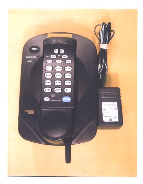
DK4CT910
Sep 30, 1999900 MHz Cordless Telephone
Equipment Class
ETS - Part 15 Cordless Telephone System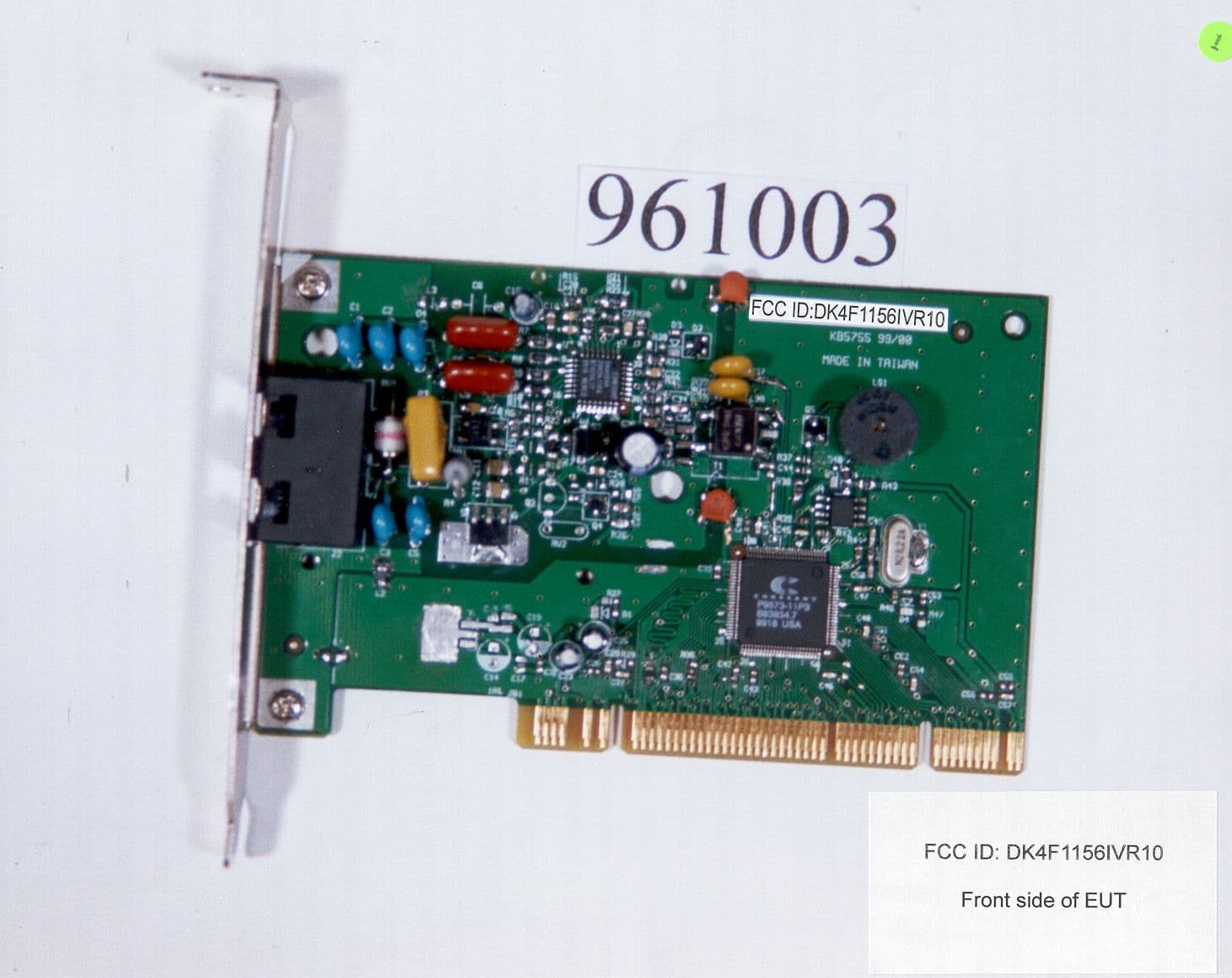
DK4F1156IVR10
Aug 10, 1999Data Fax Modem
Equipment Class
JBC - Part 15 Class B Computing Device/Personal Computer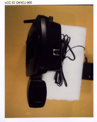
DK4CT900
Jul 18, 1999900 MHz Cordless Telephone
Equipment Class
ETS - Part 15 Cordless Telephone System