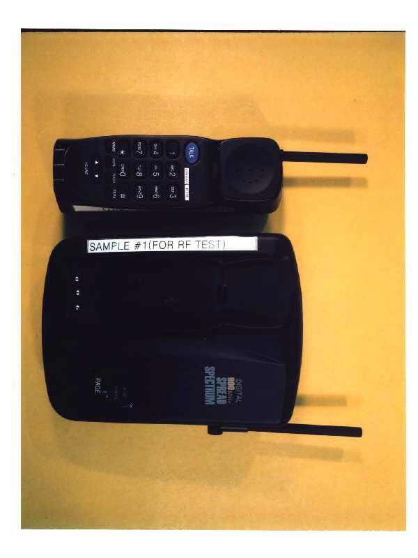
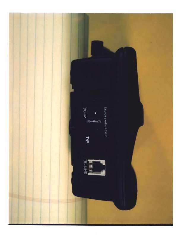
DK4CT9000900 MHZ CORDLESS TELEPHONE
GVC Corporation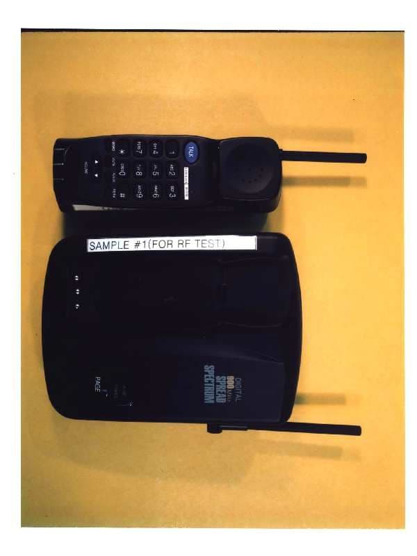
Click to zoom
Application Details
- Equipment Class
- DSS - Part 15 Spread Spectrum Transmitter
- Date of Grant
- Feb 18, 1999
- Application Purpose
- Original Equipment
- Date of Application
- Nov 02, 1998
- Equipment Note
- 900 MHZ CORDLESS TELEPHONE
- Frequency Range
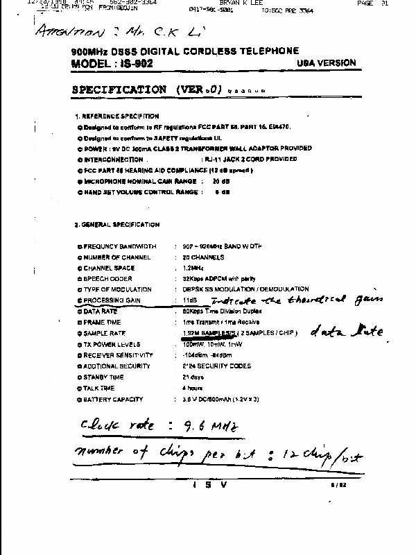
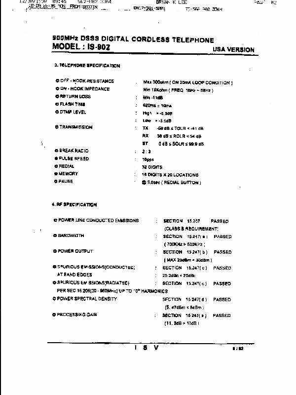
- 903.60000000 - 926.40000000
- Company
- GVC Corporation
- Country
- Taiwan
Documents & Files
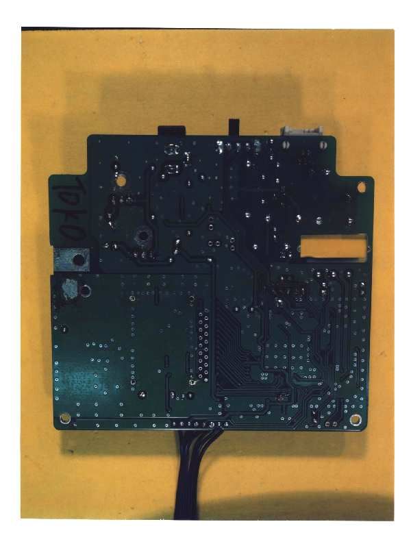
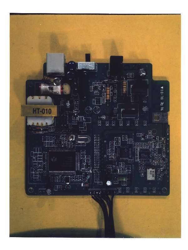
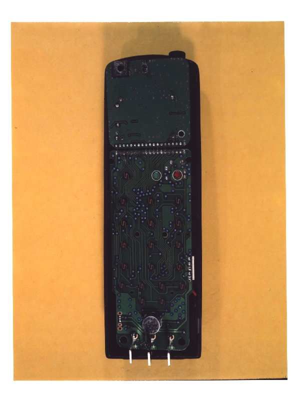
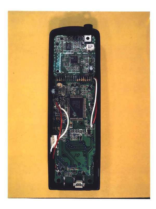
Document Text
Text extracted from the exhibit documents filed with the FCC. Open a document above to read the original.
Users Manual
(12/3/98) 90OMHz DSSS DIGITAL CORDLESS TELEPHONE MODEL: IS-901 USA VERSION USER'S MANUAL 71 / 82 90OMHz DSSS DIGITAL CORDLESS TELEPHONE MODEL: IS-901 USA VERSION ,/IMPORTANT Read this manual before attempting to setup or use this instrument. If contains important Information regarding safe installation and use. Keep this manual for future reference. Also save the carton, packing and proof of purchase to simplify and accelerate any needed action. ,/WARNING To prevent fire or shock hazard, do not expose this product to rain or any type of moisture. If accidentally dropped into water, this product should immediately by unplugged from the AC Outlet and telephone wall jack. THIS SYMBOL IS INTENDED TO ALERT THE USER OF THE PRESENCE OF IMPORTANT OPERATING AND MAINTENANCE(SERVICING)INSTRUCTIONS IN THE OWNER'S MANUAL. - INSTALLATION PRECAUTION 1. Never install telephone wiring during a lighting storm. 2. Never install telephone jacks in wet locations unless the jack is specially designed for wet locations. 3. Never touch insulated telephone wireless or terminals unless the telephone line has been disconnected at the network interface. 4. Use caution when installing or modifying telephone lines. - MAINTENANCE 1. Use a damp cloth to the plastic cabinet. A mind soap will help to remove grease or oil. Never use polish, solvents, abrasives or strong detergents since these can damage the finish. 2. Your phone should be situated away from heat sources such as radiators, heater, stoves or any other appliance that produces heat. if CAUTION To reduce the risk of fire or injure to persons, read and follow these instructions: 1.Use only the following type and the size battery 6OOmAh, 3.6V. 2.Do not dispose of the battery in a fire. The cell may explode. Check with local codes for possible special disposal instructions. 3.Do not open or mutilate the battery. Released electrolyte is corrosive and may be toxic if swallowed. 72/82 90OMHz DSSS DIGITAL CORDLESS TELEPHONE MODEL: IS-901 USA VERSION 4.Exercise care in handling in order not to short the battery with conducting material such as rings, bracelets and keys. The battery or conductor may overhead and cause burns. 5.Recharge only the battery type that is provided with or identified for use with this product. If a different type of battery is used, it may leak or explode. 6.Do not attempt to rejuvenate the battery provided with or identified for use with this product by heating them. Sudden release of the battery electrolyte may occur, causing burns or irritation to eyes or skin. 7.When inserting the battery into this product, the proper polarity or direction must be observed. Reverse insertion of battery may result in leakage or explosion . 8.Remove the battery from this product if the product will not be used for a long period of time(several months or more)since during this time they could leak in the product. 9.Discard the "dead" battery as soon as possible since "dead" battery are more likely to leak in a product. 10. Do not store this product, or the battery provided with or identified for use this product, in high-temperature areas. Baftery that are stored in a freezer or refrigerator for the purpose of extending shelf life should be stabilized at room temperature prior to use after cold storage. 11. Alwaysdisconnectalltelephonelinecordsfromthewallmodularjacksbeforeinstallin gor replacing the battery. - IMPORTANT SAFETY INSTRUCTIONS When using your telephone equipment, basis safety precautions should always be followed to reduce the risk of life electric shock, and injury to persons, including the following. 1 .Read and understand all instructions. 2. Follow all warnings and instructions marked on the product. 3. Unplug this product from the outlet before cleaning. Do not use liquid cleaners or aerosol cleaners. Use a damp cloth for cleaning. 4. Do not use this product near water, for example, near a bathtub, wash bowl, kitchen sink, or laundry tub in a wet basement or near a swimming pool. 5. Do not place this product on an unstable cart, stand, or table. The product may fall, causing serious damage to the product. 6. Slots and openings in the cabinet and the back or bottom are provide for ventilation, to protect it from overheating. These openings should never be blocked or covered. The opening should never be blocked by placing the product on the bed, sofa, rug, or other similar surface. This product should never be placed near or over a radiator or heat register. This product should not be placed in a built in installation unless proper ventilation is provided., 7. This product should be operated only from the type of power source indicated on the marking label. If you are not sure of the type of power supply to your home, consult your dealer or local power company. 73 / 82 90OMHz DSSS DIGITAL CORDLESS TELEPHONE MODEL: IS-901 USA VERSION 8. Do not allow anything to rest on the power cord. Do not locate this product where the cord will be abused by persons walking on it. 9. Do not overload wall outlets and extension cords as this can result in the risk of fire or electric shock. 10.Never push objects of any kind into this product through cabinet slots as they may touch dangerous voltage points or short out parts that could result in a of fire or electric shock. Never spill liquid of any kind on the product. 11.To reduce the risk of electric shock, do not disassemble this product, but take it to a qualified service contractor when some service or removing covers may expose you to dangerous voltages or other risks. Incorrect reassembly can cause electric shock when the appliance is subsequently used. 12.Unplug this product from the wall outlet and refer servicing to qualified service personnel under the following conditions: A.When the power supply cord or plug is damaged or frayed. B.If liquid has been spilled into the product. C.If the product has been exposed to rain or water. D.If the product does not operate normally by following the operating in…
Text truncated - open the document above for the full version.
Users Manual
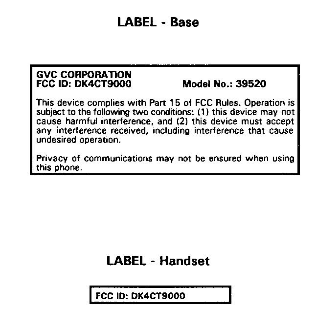
(12/3/98) 90OMHz DSSS DIGITAL CORDLESS TELEPHONE MODEL: IS-901 USA VERSION USER'S MANUAL 76 82 90OMHz DSSS DIGITAL CORDLESS TELEPHONE MODEL: IS-901 USA VERSION IS-901 CONTROLS DIAGRAM (illustrations not shown to scale) This device complies with Part 15 of the FCC Rules. Operation is subject to the following two conditions: (1) This device may not cause harmful interference, and (2) this device must accept any interference received, Including interference that may cause undesires operation. Privacy of communications may not be insured when using the phone. Changes or modifications not expressly approved by GVC Corporation could void the user’s authority to operate the equipment.
Block Diagram
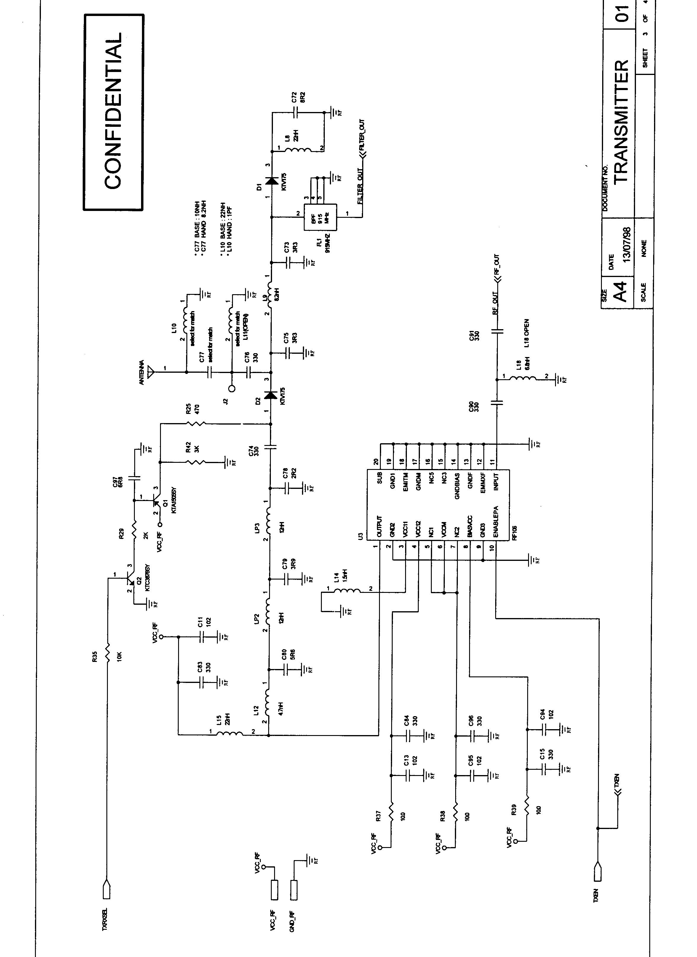
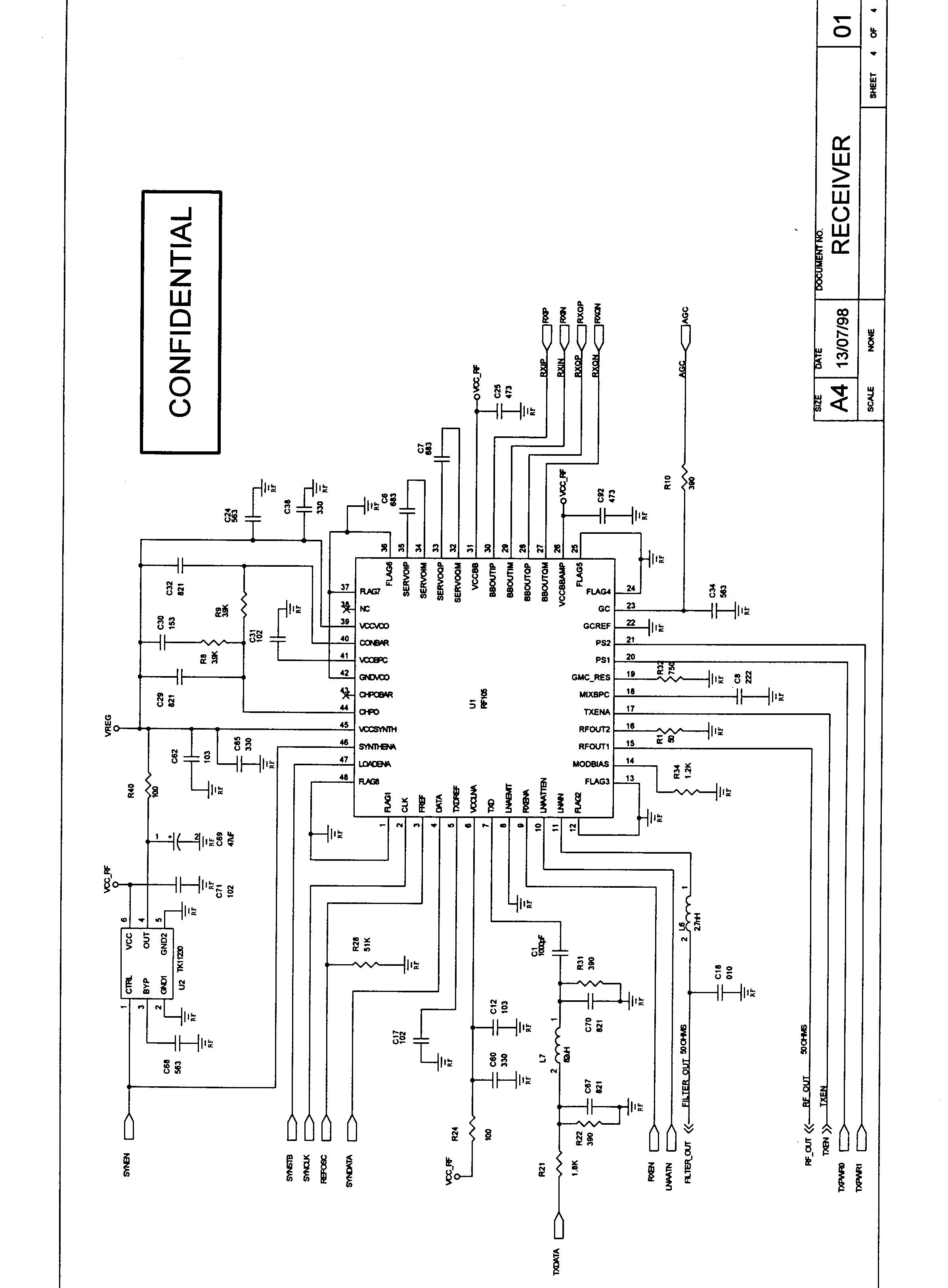
900MHz DSSS DIGITAL CORDLESS TELEPHONE MODEL : IS-901 USA VERSION I S V 1 / 5 BLOCK DIAGRAM 900MHz DSSS DIGITAL CORDLESS TELEPHONE MODEL : IS-901 USA VERSION I S V 2 / 5 IS-901System Architecture DCT Spread Spectrum Engine Block Diagram TX DATA RADIO RX(I) RX(Q) MODULATOR DIFF.ENCODER SPREADERTX DATA BUFFER 16BIT PARALLEL TO SERIAL SCRAMBLER/ DESCRAMBER DAC AGC FREQ. COMPE - NSATION A/D MACHED FILTER 16BIT SERIAL TO PARALLEL DATA DEMODULATOR RX BUFFER A/D EEPROM EEPROM LINE INTERFACE RINGER MICROPHONE CODEC CODECASIC ASIC KEY PAD RF TRANSCEIVER RF TRANSCEIVER PSTN 900MHz DSSS DIGITAL CORDLESS TELEPHONE MODEL : IS-901 USA VERSION I S V 3 / 5 ⊗ ⊗ ⊗ ÷ ÷ ⊗ RF Block Diagram RF LPF RF SWITCH 902-928 MHz BPF LNA PA LEVEL CONTROL POWER MANAGEMENT VARIABLE GAIN AMPLIFIER LPFLPF LPF LPF LPF LPF LPF 90° FREQUENCY SYNTHESIZER PAPRE- AMP VCO 3 LNAATN RXIP RXIQ AGC REF OSC SYADATA SYACLK SYASTB TX DATA TX/RX SEL RXEN TXEN SYNEN
Cover Letter(s)
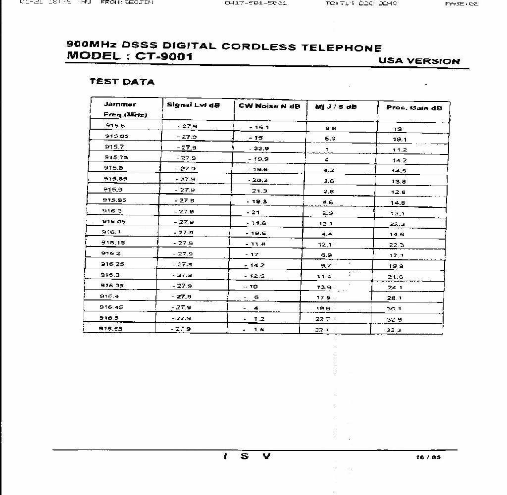
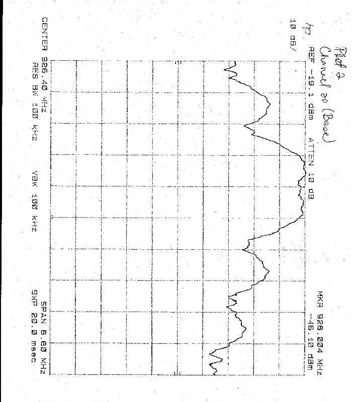
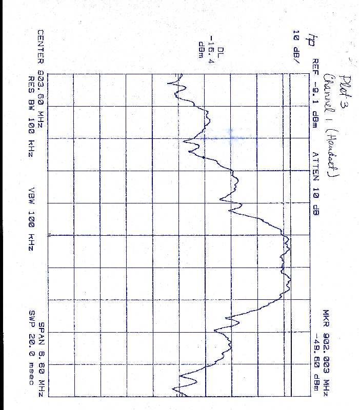
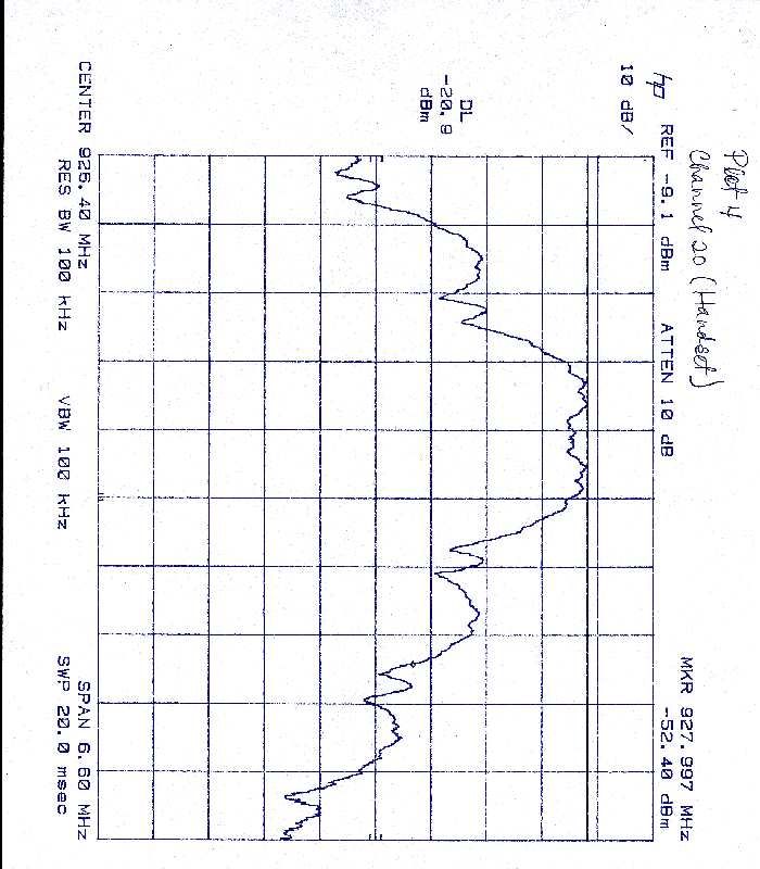
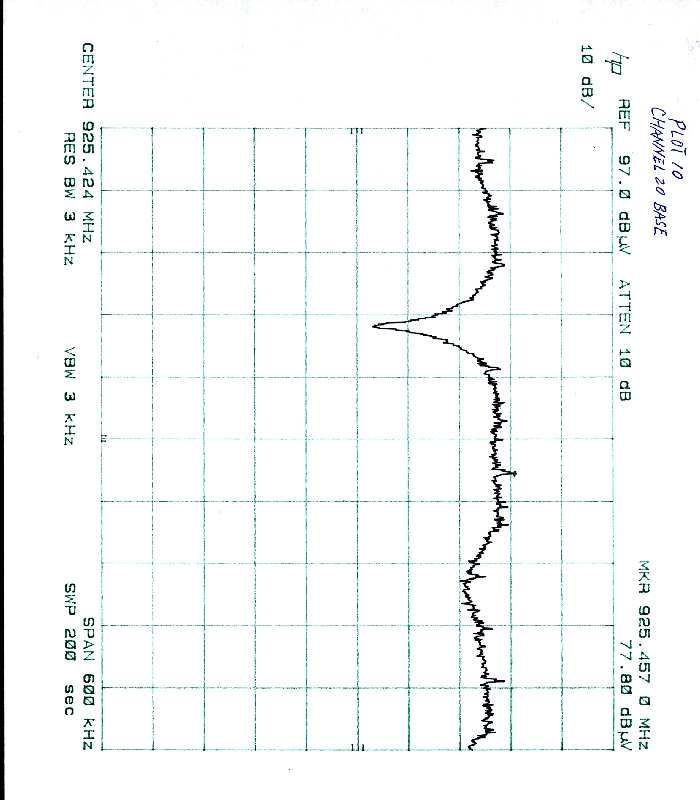
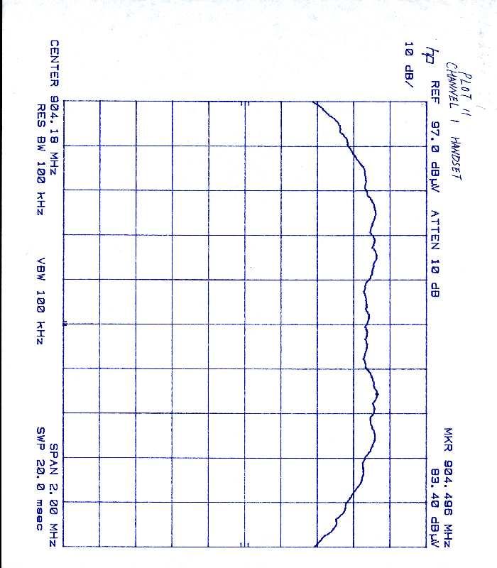
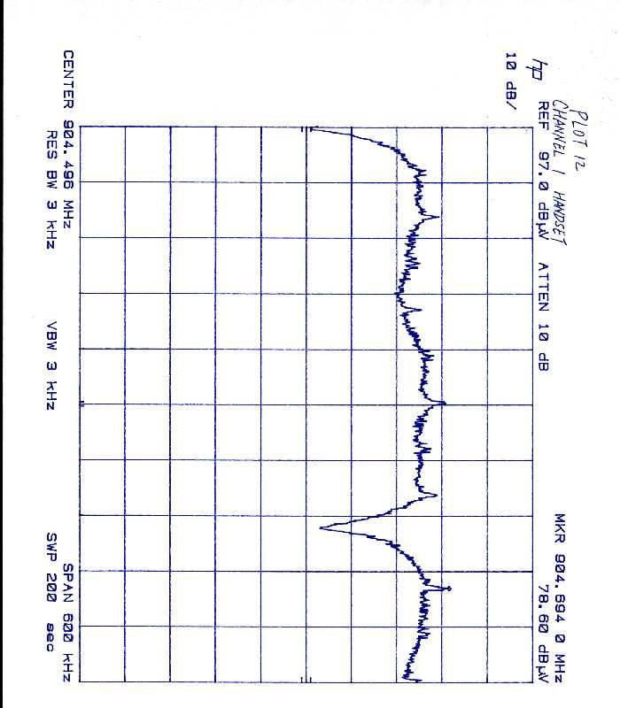
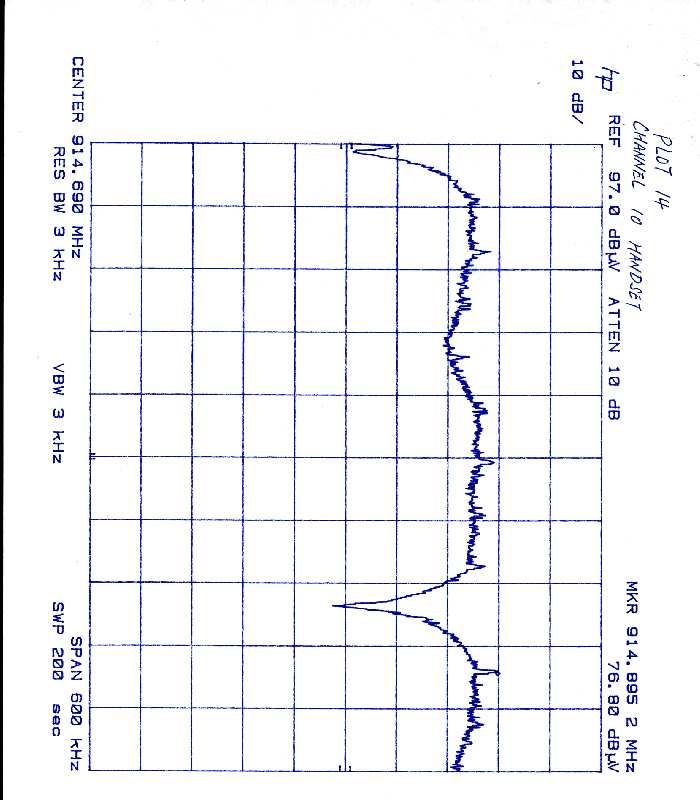
A January 12, 1999 LTO# J98026020 Federal Communications Commission Equipment Authorization Division Applications Processing Branch 7435 Oakland Mills Road Columbia, MD 21046 Attention:Mr. Joe Dichoso Reference:FCC Certification Application for GVC Corporation FCC ID: DK4CT9000, Conf. # EA92202, Ref. # 5079 Dear Mr. Dichoso: This is in reply to Items 6 & 7 of the information request dated December 10, 1998 for the above application. Item 6: The plots submitted were made at the lowest channel (Channel 1) and highest channel (Channel 20). Please refer to the attached “Frequency Table”. It looks like the center frequency shifted 500 kHz away from the band edge. I think it is the way it was designed. If the plots are not clear, we will resubmit it. Item 7: The power test and power density test were done as follows: 1.We disconnected the antenna from the EUT. 2.We connected the RF output directly to the input of the spectrum analyzer thru a low loss cable. We think this method will give us a better control and more accurate reading. Should you need more or have any questions, please contact the undersigned. Sincerely, Xi-Ming Yang Test Engineer A
Cover Letter(s)
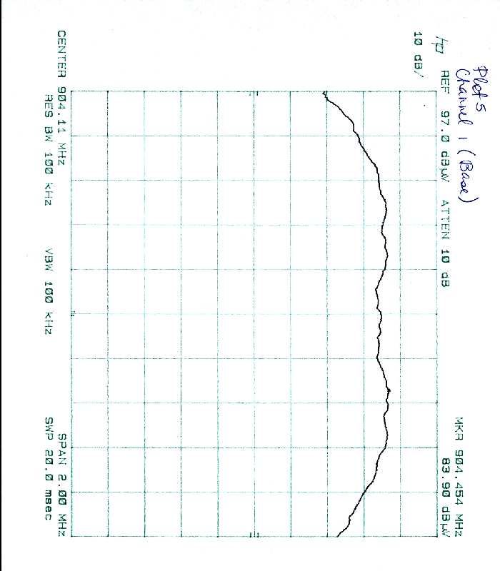
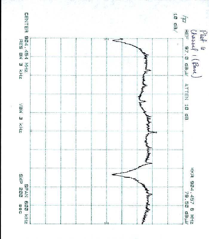
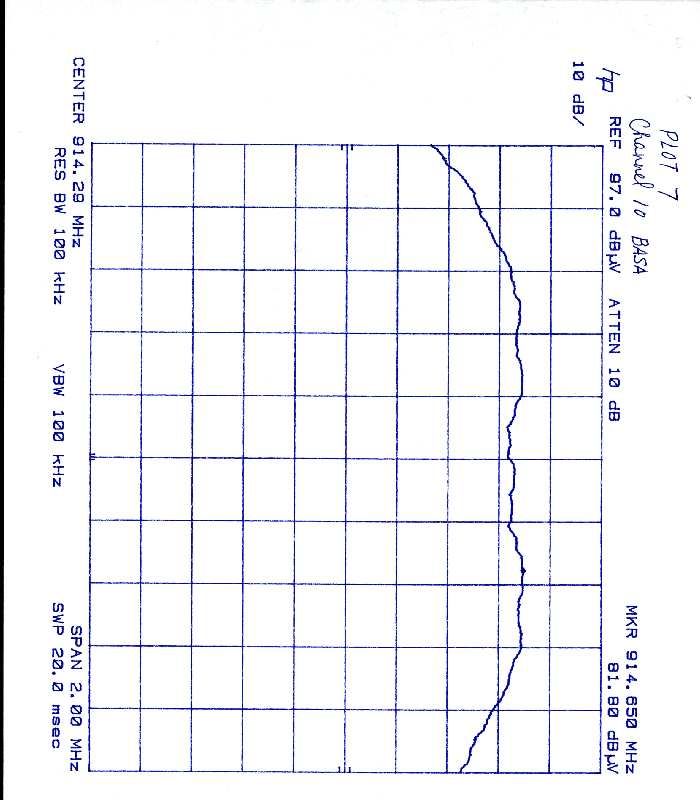
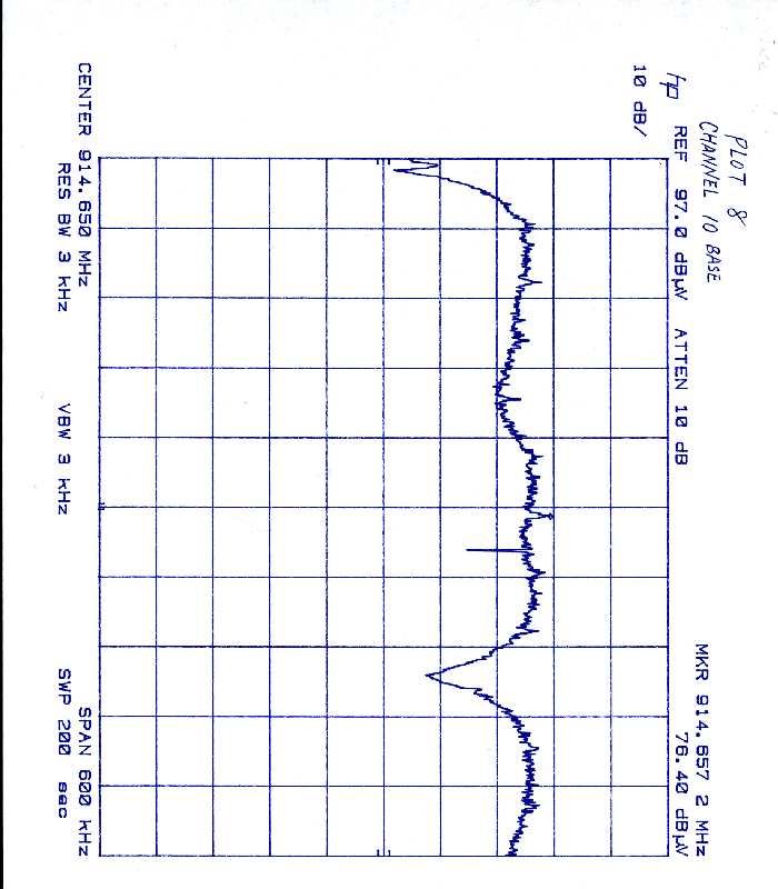
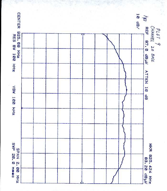
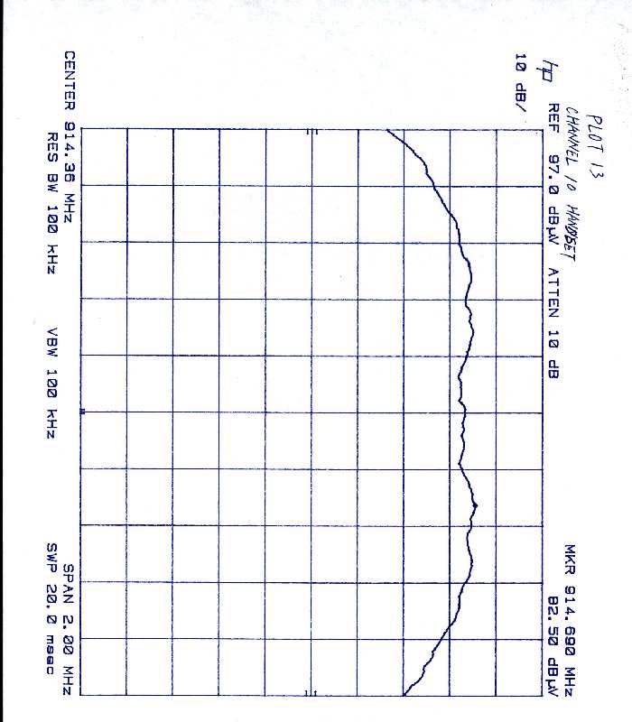
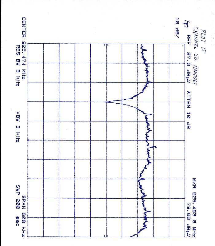
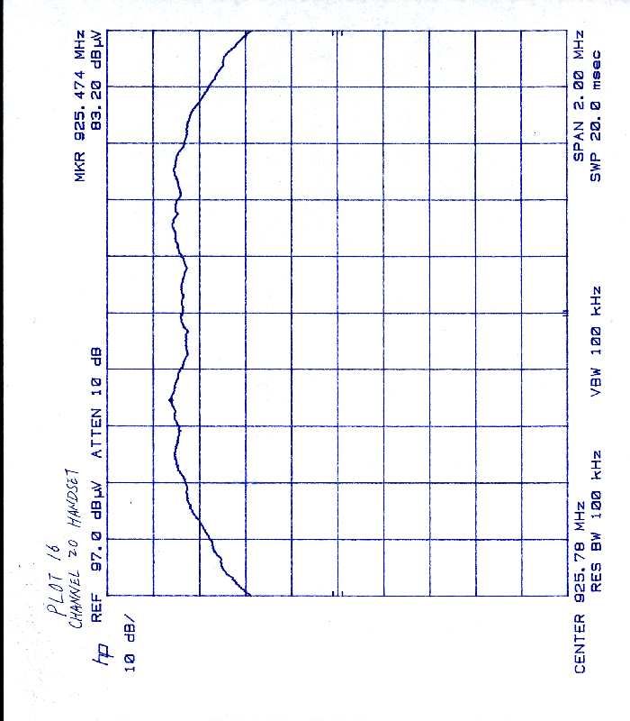
January 21, 1 999 Federal Communications Commission Equipment Authorization Division Applications Processing Branch 7435 Oakland Mills Road Columbia, MD 21046 Attention:Mr. Joe Dichoso Subject:Reference No.: 5604, Confirmation No.: EA92202 FCC ID: DK4CT9000 Applicant: GVC Corporation Dear Mr. Dichoso: This is in response to your letter of January 1, 1999 regarding the above referenced application. For Item 1 & Item 2: Process gain test data and the bandedge Plots 1-4, (Channel 1 and Channel 20 for both handset and base) are submitted today under “Add Attachment”. For Item 3: Alternative test procedures were used to measure the peak power. ERP is more than 0.08W which is closer to 0.1W as per the users manual. Also the power density was retested (see Plots 5-16) under “Add Attachment”. Worst Case: 79.5 dBuV (spectrum reading) + 22.9 dB (Antenna Factor) + 1.3 dB Cable Loss = 103.7 dBuV/m (at 3m) 103.7 - 97.4 = 6.3 dBm (Effective Radiated Power Density) Should you have any questions, please contact the undersigned. Sincerely, Xi-Ming Yang Test Engineer
Test Report
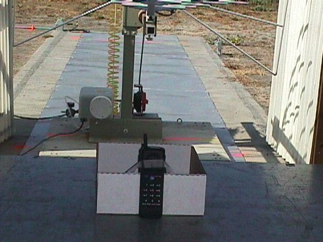
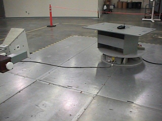
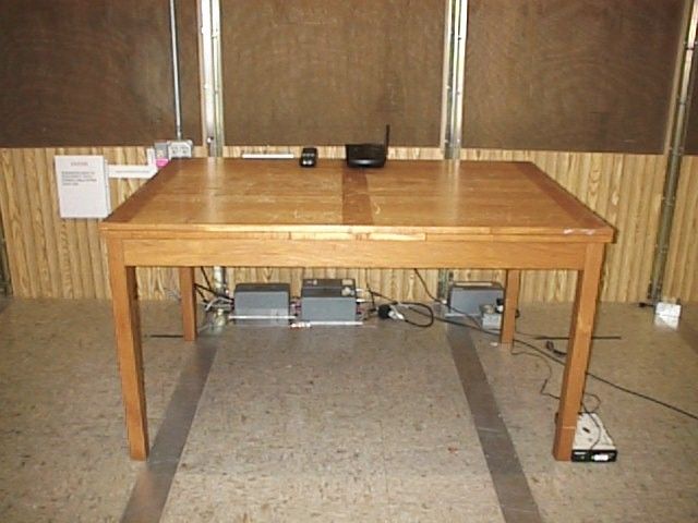
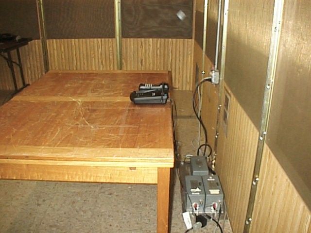
Intertek Testing Services APPLICATION FOR FCC CERTIFICATION GVC Corporation 900 MHz DSSS Cordless Telephone Model: 39520 FCC ID: DK4CT9000 Job # J98026020 Number of Pages: 14 pp. + Supporting Data and Documents Date of Report: October 12, 1998 This report shall not be reproduced except in full, without written approval of Intertek Testing Services. This report must not be used to claim product endorsement by NVLAP or any agency of the U.S. Government. The results contained in this report were derived from measurements performed on the identified test samples. Any implied performance of other samples on this report is dependent on the representative of the samples tested. k:\..\fcc\15247ds.cerFCC Part 15 DSSS Cert, Ver 8/98 Intertek Testing Services 1365 Adams Court, Menlo Park, CA 94025 GVC Corporation, 900 MHz DSSS Digital Cordless TelephoneDate of Test: 9/29/98 - 10/05/98 FCC ID: DK4CT9000 Report # J98026020FCC Part 15.247 DSSS Certification ii Table of Contents 1.0Summary of Tests ...............................................................1 2.0General Description..............................................................2 2.1Product Description........................................................2 2.2Related Submittal(s) Grants..................................................2 2.3Test Methodology..........................................................3 2.4Test Facility..............................................................3 3.0System Test Configuration ........................................................4 3.1Support Equipment.........................................................4 3.2Block Diagram of Test Setup.................................................4 3.3Justification..............................................................5 3.4Software Exercise Program..................................................5 3.5Mode of Operation During Test...............................................5 3.6Modifications Required for Compliance........................................5 3.7Additions, deviations and exclusions from standards..............................5 4.0Measurement Results ............................................................6 4.1Maximum Conducted Output Power at Antenna Terminals.........................6 4.2Minimum 6 dB RF Bandwidth...............................................8 4.3Maximum Power Density Reading............................................9 4.4Out of Band Conducted Emissions...........................................10 4.5Out of Band Radiated Emissions.............................................10 4.6Transmitter Radiated Emissions in Restricted Bands.............................10 4.7AC Line Conducted Emission...............................................11 4.10Radiated Emissions from Digital Section of Transceiver (Transmitter), ..............12 4.11Radiated Emissions from Receiver Section of Transceiver (L.O. Radiation), ..........12 4.12Processing Gain Measurements..............................................13 4.13Transmitter Duty Cycle Calculation and Measurements...........................13 5.0List of Exhibits ................................................................14 Intertek Testing Services 1365 Adams Court, Menlo Park, CA 94025 GVC Corporation, 900 MHz DSSS Digital Cordless TelephoneDate of Test: 9/29/98 - 10/05/98 FCC ID: DK4CT9000 Report # J98026020FCC Part 15.247 DSSS Certification 1 1.0Summary of Tests GVC Corporation - Model No.: 39520 FCC ID: DK4CT9000 TESTREFERENCERESULTS Max. Output power 15.247(b)Pass 6 dB Bandwidth15.247(a)(2)Pass Max. Power Density15.247(d)Pass Out of Band Antenna Conducted Emission15.247(c)Pass Out of Band Radiated Emission15.247(c)N/A Radiated Emission in Restricted Bands15.35(b)(c)Pass AC Conducted Emission15.207Pass Radiated Emission from Digital Part15.109Pass Radiated Emission from Receiver L.O.15.109Not Applicable Processing Gain Measurements15.247(e)Provided by applicant Antenna Requirement15.203Pass* * EUT has non-detachable antenna. Test Engineer:Date: October 19, 1998 Xi-Ming Yang EMC Site Manager: Date: October 20, 1998 David Chernomordik Intertek Testing Services 1365 Adams Court, Menlo Park, CA 94025 GVC Corporation, 900 MHz DSSS Digital Cordless TelephoneDate of Test: 9/29/98 - 10/05/98 FCC ID: DK4CT9000 Report # J98026020FCC Part 15.247 DSSS Certification 2 2.0General Description 2.1Product Description The Model 39520 is a 900 MHz DSSS digital cordless telephone. A pre-production version of the sample was received on September 29, 1998 in good condition. Overview of 900 MHz DSSS Cordless Telephone Applicant GVC Corporation Trade Name & Model No. GVC Corporation, Memorex, 39520 FCC Identifier DK4CT9000 Use of ProductCordless Telephone Manufacturer & Model ofGVC Corporation Spread Spectrum Module Type of TransmissionDirect Sequence Rated RF Output (mW)100 Frequency Range (MHz)903.6 - 926.4 Number of Channel(s)20 Antenna(s) & Gain, dBi0 Processing Gain[X]Will be provided to ITS for submission with the application Measurements[ ]Will be provided directly to the FCC reviewing engineer by the client or manufacturer of the spread spectrum module Antenna Requirement[X]The EUT uses a permanently connected antenna. [ ]The antenna is affixed to the EUT using a unique connector which allows for replacement of a broken antenna, but DOES NOT use a standard antenna jack or electrical connector. [ ]The EUT requires professional installation (attach supporting documentation if using this option). Manufacturer name & addressGVC Corporation 4F, No. 6, Lane 359, Sec. 2, Chung-shan Rd., Chung-Ho, Taipei, Taiwan, R.O.C. 2.2Related Submittal(s) Grants None. Intertek Testing Services 1365 Adams Court, Menlo Park, CA 94025 GVC Corporation, 900 MHz DSSS Digital Cordless TelephoneDate of Test: 9/29/98 - 10/05/98 FCC ID: DK4CT9000 Report # J98026020FCC Part 15.247 DSSS Certification 3 2.3Test Methodology Both AC mains line-conducted and radiated emissions measurements were performed acc…
Text truncated - open the document above for the full version.
Test Report
Intertek Testing Services GVC Corporation 900 MHz DSSS Cordless Telephone Model: 39520 FCC ID: DK4CT9000 Job # J98026020 Pages 65to 72 of the Test Report Intertek Testing Services 1365 Adams Court, Menlo Park, CA 94025 GVC Corporation, 900 MHz DSSS Digital Cordless TelephoneDate of Test: 9/29/98 - 10/05/98 FCC ID: DK4CT9000 Report # J98026020FCC Part 15.247 DSSS Certification 65 Intertek Testing Services 1365 Adams Court, Menlo Park, CA 94025 GVC Corporation, 900 MHz DSSS Digital Cordless TelephoneDate of Test: 9/29/98 - 10/05/98 FCC ID: DK4CT9000 Report # J98026020FCC Part 15.247 DSSS Certification 66 Intertek Testing Services 1365 Adams Court, Menlo Park, CA 94025 GVC Corporation, 900 MHz DSSS Digital Cordless TelephoneDate of Test: 9/29/98 - 10/05/98 FCC ID: DK4CT9000 Report # J98026020FCC Part 15.247 DSSS Certification 67 Intertek Testing Services 1365 Adams Court, Menlo Park, CA 94025 GVC Corporation, 900 MHz DSSS Digital Cordless TelephoneDate of Test: 9/29/98 - 10/05/98 FCC ID: DK4CT9000 Report # J98026020FCC Part 15.247 DSSS Certification 68 Intertek Testing Services 1365 Adams Court, Menlo Park, CA 94025 GVC Corporation, 900 MHz DSSS Digital Cordless TelephoneDate of Test: 9/29/98 - 10/05/98 FCC ID: DK4CT9000 Report # J98026020FCC Part 15.247 DSSS Certification 69 Intertek Testing Services 1365 Adams Court, Menlo Park, CA 94025 GVC Corporation, 900 MHz DSSS Digital Cordless TelephoneDate of Test: 9/29/98 - 10/05/98 FCC ID: DK4CT9000 Report # J98026020FCC Part 15.247 DSSS Certification 70 Intertek Testing Services 1365 Adams Court, Menlo Park, CA 94025 GVC Corporation, 900 MHz DSSS Digital Cordless TelephoneDate of Test: 9/29/98 - 10/05/98 FCC ID: DK4CT9000 Report # J98026020FCC Part 15.247 DSSS Certification 71 Intertek Testing Services 1365 Adams Court, Menlo Park, CA 94025 GVC Corporation, 900 MHz DSSS Digital Cordless TelephoneDate of Test: 9/29/98 - 10/05/98 FCC ID: DK4CT9000 Report # J98026020FCC Part 15.247 DSSS Certification 72
Test Report
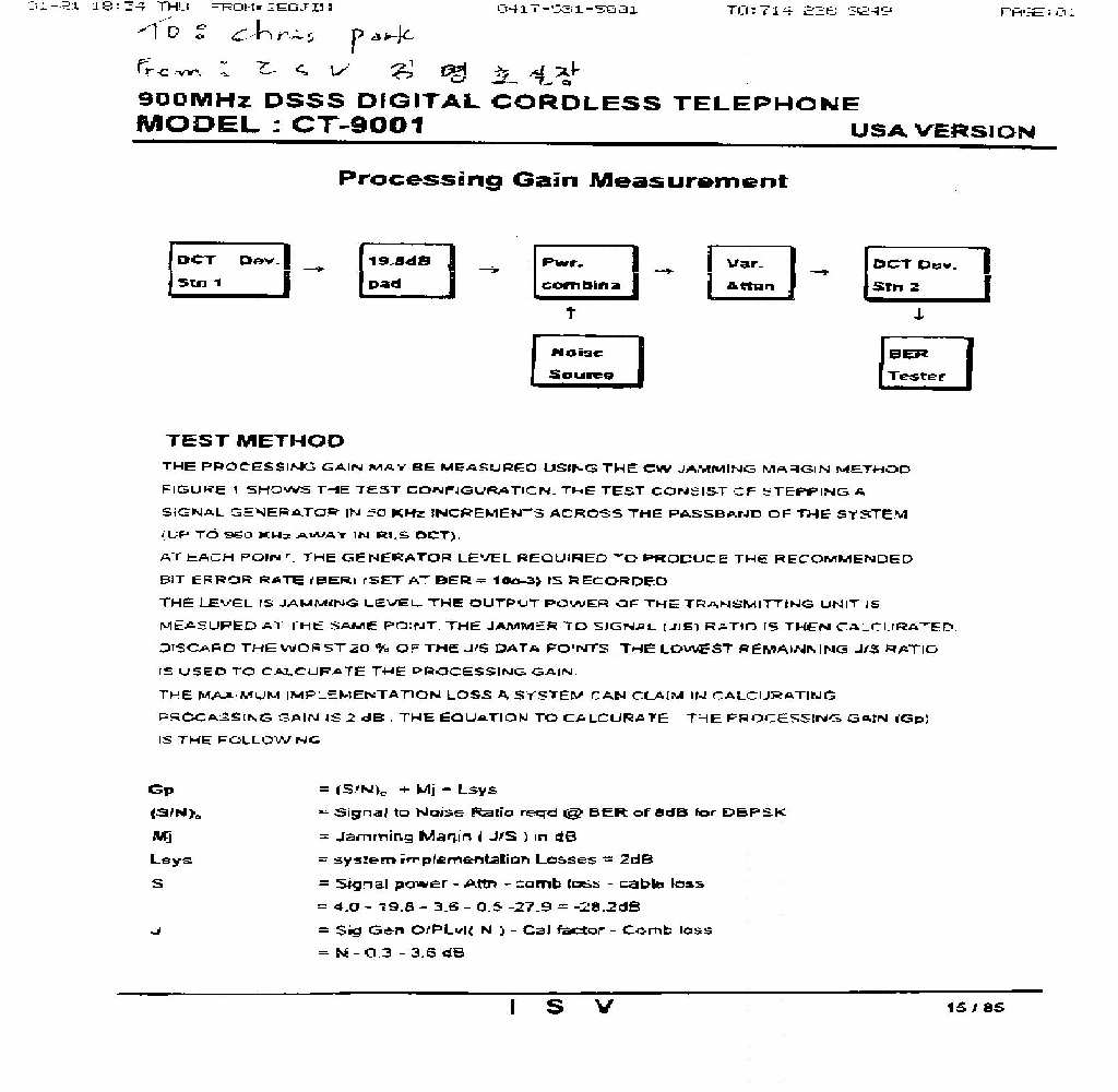
Processing Gain Measurements for MH9027 DCT TEST report 1. Introduction 1.1 Scope This document is a ISV Engineering test report for MH9027 basic DCT cordlessphone. This document details the results of measurement of the processing gain of a DCT FFF phone. 1.2 Reference Documents This section lists documents that are referenced within or are materially relevant to this document. Code of Federal Regulations, Title 47, Chapter 1, Part 15 Radio Frequency Devices (FCC) 1.3 Definitions FCCFederal Communications Commission SNRSignal to Noise Ratio JSRJammer to Signal Ratio CWContinuous wave (jammer) HSHandset BSBasestation DBPSKDifferential Binary Phase Shift Keying Table 1: Definitions and Abbreviations 2. An Overview of the FCC Method for measuring Processing Gain Two methods are specified for measuring processing gain by the FCC in 15.247 (e). The first method simply involves calculating the signal to ratio noise (SNR) with the spreading code switched on with the SNR when the spreading code is switched off. The difference between the two is the processing gain. The SNR is measured at the demodulated output of the receiver. In principle this an acceptable method to measure the processing gain of any direct sequence spread spectrum communication system, however, it does not take into consideration that the non-spread spectrum portion of the system may operate under the assumption that the signal being transmitted is a spread spectrum signal and when the spreading code is switched off the system may fail to operate or operate at greatly reduced efficiency, In either case the measurement of processing gain will be meaningless. The second method specified by the FCC to measure processing gain is detailed in 15.247 (e)(1). This involves transmitting a CW jammer in the RF passband of the system and measuring the jammer to signal ratio (JSR) required to achieve a certain bit error rate. The choice of the actual value of the bit error rate is left up to the tester. The jammer is stepped in 50 kHz increments across the entire passband and in each case the JSR to achieve the desired bit error rate is measured. The JSR is measured at the RF input to the system under test. The lowest 20% of the JSR data (in dB) is discarded. The processing gain can then be calculated as follows:- system measuredtheory p L S J N S G+ ö ç è æ + ÷ ö ç è æ = where G p is the processing gain, the SNR is that theoretically predicted for the system under the test to achieve the desired bit error rate, the JSR is the lowest value (in dB) in the remaining data set and L sys adjusts for non-ideal system losses. L sys can not be greater than 2 dB. 3. Processing Gain Measurement Results The following parameters were used in the test setup. HS Tx power (dBm)-4.3 BS LNA gain (dB)0 Test system losses (signal) (dB) -14.55-4.05 dB (system), -3 dB (signal combiner), -7.5 dB (2 cables) Test system losses (jammer) (dB) -5.6-3 dB (signal combiner), -2.6 dB (2cables) Table 2: Test Setup Parameters The following measurement results were taken at the basestation. The desired bit error rate was set at 10 -3 . Jammer Frequency (MHz) BER (BS)Received jammer power (dBm) Received signal power (dBm) Jammer/Signal ratio (dB) 903.60 9.95×10 -4 --15.2-17.11.9 904.80 1.25×10 -3 -14.9-16.92.0 906.00 9.6×10 -4 -15.0-17.32.3 907.20 9.6×10 -4 -14.5-16.82.3 908.40 1.23×10 -3 -14.9-17.42.5 909.60 9.8×10 -4 -15.3-17.21.9 910.80 1.13×10 -3 -14.7-16.92.2 912.00 9.23×10 -4 -14.8-16.61.8 913.20 1.12×10 -3 -14.9-17.12.2 914.40 1.2×10 -3 -14.8-16.92.1 915.60 9.89×10 -4 -15.0-17.52.5 916.80 1.11×10 -3 -14.7-16.92.2 918.00 1.21×10 -3 -15.2-16.91.7 919.20 1.08×10 -3 -14.9-17.02.1 920.40 9.87×10 -4 -15.1-17.32.2 921.60 1.8×10 -3 -15.3-17.62.3 922.80 9.87×10 -4 -15.1-17.62.5 924.00 1.54×10 -3 -15.3-17.01.7 925.20 1.65×10 -3 -15.3-17.32.0 926.40 9.0×10 -4 -15.6-17.41.8 Table 3: Test Results –4.3 (at 10CH) Figure 1: Test Setup For DBPSK at 10 -3 bit error rate the required SNR is 8.0 dB. Using the results above and the data in the table below the processing gain is calculated to be 12.1 dB. required SNR (dB)8.0 system losses (dB)2.0 J/S ratio at 80% point (dB)2.1 FCC Processing gain (dB) 12.1 Table 4: Processing Gain Calculation data 4. Conclusions The result measured for processing gain of 12.1 dB is close to the actual processing gain due to a 12 chip spreading code of 10 × log 10 (12) = 10.8 dB cable Cable -1.3dB additional system loss (-4.05 dB) (voice signal only) Signal Combiner -3 dB (-6.2 dB) RF Signal Generator (HP8663A) Cable -1.3dB At 10 CH Received jammerpower :-14.8 Received signal power : -16.9 -1.3dB
Test Report
A Company:GVC Corporation Project #:J98026020 Model:39520 (Handset Tx) Engineer:Xi-Ming Yang Date of test: January 21, 1999 FCC 15.247 Radiated Emissions(Output Power) FrequencyAntennaReadingAntennaCableCorrectedEUTERPERP PolarityFactorLossReadingAnt Gan MHzH/VdB(uV)dB(1/m)dBdB(uV/m)dBdBmWatts 903.6V92.522.71.3116.5-1.619.70.933 914.4V92.122.91.3116.3-1.619.50.891 926.4V92.222.71.3116.2-1.619.40.871 Note:1. All measurement were made at 3 meters 2. Output Power (EIRP) P(w) = (E*d)squared/30 10log P = 10log((E*d)squared/30) P(dBw) = 10log((d)squared/30) + 10log ((E) squared) P(dBm) - 30dB = 10log(9/30) + 20log(E) d = 3m P(dBm) - 30dB = -5.23dB + E(dBuV/m) - 120dB P(dBm) = E(dBuV/m) - 95.2dB 3. Output Power (ERP)= Output Power(EIRP)-1.6(EUT Ant Gan) A Company:GVC Corporation Project #:J98026020 Model:39520 (Base Tx) Engineer:Xi-Ming Yang Date of test: January 21, 1999 FCC 15.247 Radiated Emissions(Output Power) FrequencyAntennaReadingAntennaCableCorrectedEUTERPERP PolarityFactorLossReadingAnt Gan MHzH/VdB(uV)dB(1/m)dBdB(uV/m)dBdBmWatts 903.6V92.622.71.3116.6-1.619.80.955 914.4V91.822.91.3116.0-1.619.20.832 926.4V92.422.71.3116.4-1.619.60.912 Note:1. All measurement were made at 3 meters 2. Output Power (EIRP) P(w) = (E*d)squared/30 10log P = 10log((E*d)squared/30) P(dBw) = 10log((d)squared/30) + 10log ((E) squared) P(dBm) - 30dB = 10log(9/30) + 20log(E) d = 3m P(dBm) - 30dB = -5.23dB + E(dBuV/m) - 120dB P(dBm) = E(dBuV/m) - 95.2dB 3. Output Power (ERP)= Output Power(EIRP)-1.6(EUT Ant Gan) A Company:GVC Corporation Project #:J98026020 Model:39520 (Handset Tx) Engineer:Xi-Ming Yang Date of test: January 21, 1999 FCC 15.247 Radiated Emissions(Output Power Density) FrequencyAntennaReadingAntennaCableCorrectedEUTERP PolarityFactorLossReadingAnt Gan MHzH/VdB(uV)dB(1/m)dBdB(uV/m)dBdBm 904.5V78.622.71.3102.6-1.65.8 914.9V76.822.91.3101.0-1.64.2 925.5V78.622.71.3102.6-1.65.8 Note:1. All measurement were made at 3 meters 2. Output Power (EIRP) P(w) = (E*d)squared/30 10log P = 10log((E*d)squared/30) P(dBw) = 10log((d)squared/30) + 10log ((E) squared) P(dBm) - 30dB = 10log(9/30) + 20log(E) d = 3m P(dBm) - 30dB = -5.23dB + E(dBuV/m) - 120dB P(dBm) = E(dBuV/m) - 95.2dB 3. Output Power (ERP)= Output Power(EIRP)-1.6(EUT Ant Gan) A Company:GVC Corporation Project #:J98026020 Model:39520 (Base Tx) Engineer:Xi-Ming Yang Date of test: January 21, 1999 FCC 15.247 Radiated Emissions(Output Power Density) FrequencyAntennaReadingAntennaCableCorrectedEUTERP PolarityFactorLossReadingAnt Gan MHzH/VdB(uV)dB(1/m)dBdB(uV/m)dBdBm 904.5V79.522.71.3103.5-1.66.7 914.7V76.422.91.3100.6-1.63.8 925.5V77.822.71.3101.8-1.65.0 Note:1. All measurement were made at 3 meters 2. Output Power (EIRP) P(w) = (E*d)squared/30 10log P = 10log((E*d)squared/30) P(dBw) = 10log((d)squared/30) + 10log ((E) squared) P(dBm) - 30dB = 10log(9/30) + 20log(E) d = 3m P(dBm) - 30dB = -5.23dB + E(dBuV/m) - 120dB P(dBm) = E(dBuV/m) - 95.2dB 3. Output Power (ERP)= Output Power(EIRP)-1.6(EUT Ant Gan)
Contact Information
Applicant
T. C. Wu(Manager)
886 3 328-7799Fax: 886 3 397-7598
Technical Contact
Intertek Testing ServicesGaspara Lim
[email protected]650-463-2900
1365 ADAMS COURT · MENLO PARK, California · United States
Non-Technical Contact
SANFORDChris Park
714-228-9075
Test Firm
Intertek Testing Services NA Inc.John Quigley
Technical Specifications
| # | Rule Parts | Frequency Range | Power Output |
|---|---|---|---|
| 1 | 15C | 903.6 MHz - 926.4 MHz | 100.00 mW |
Other Applications from GVC Corporation
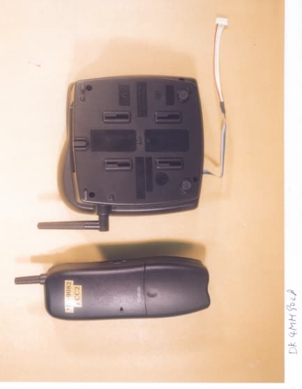
DK4MH9082
Oct 27, 1999DSS - Part 15 Spread Spectrum Transmitter
Equipment Class
DSS - Part 15 Spread Spectrum Transmitter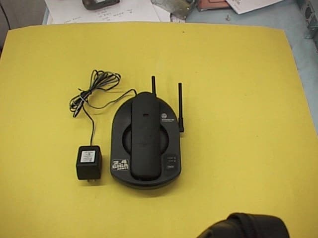
DK4GH2400
Oct 25, 1999Cordless Telephone
Equipment Class
DXT - Part 15 Low Power Transceiver, Rx Verified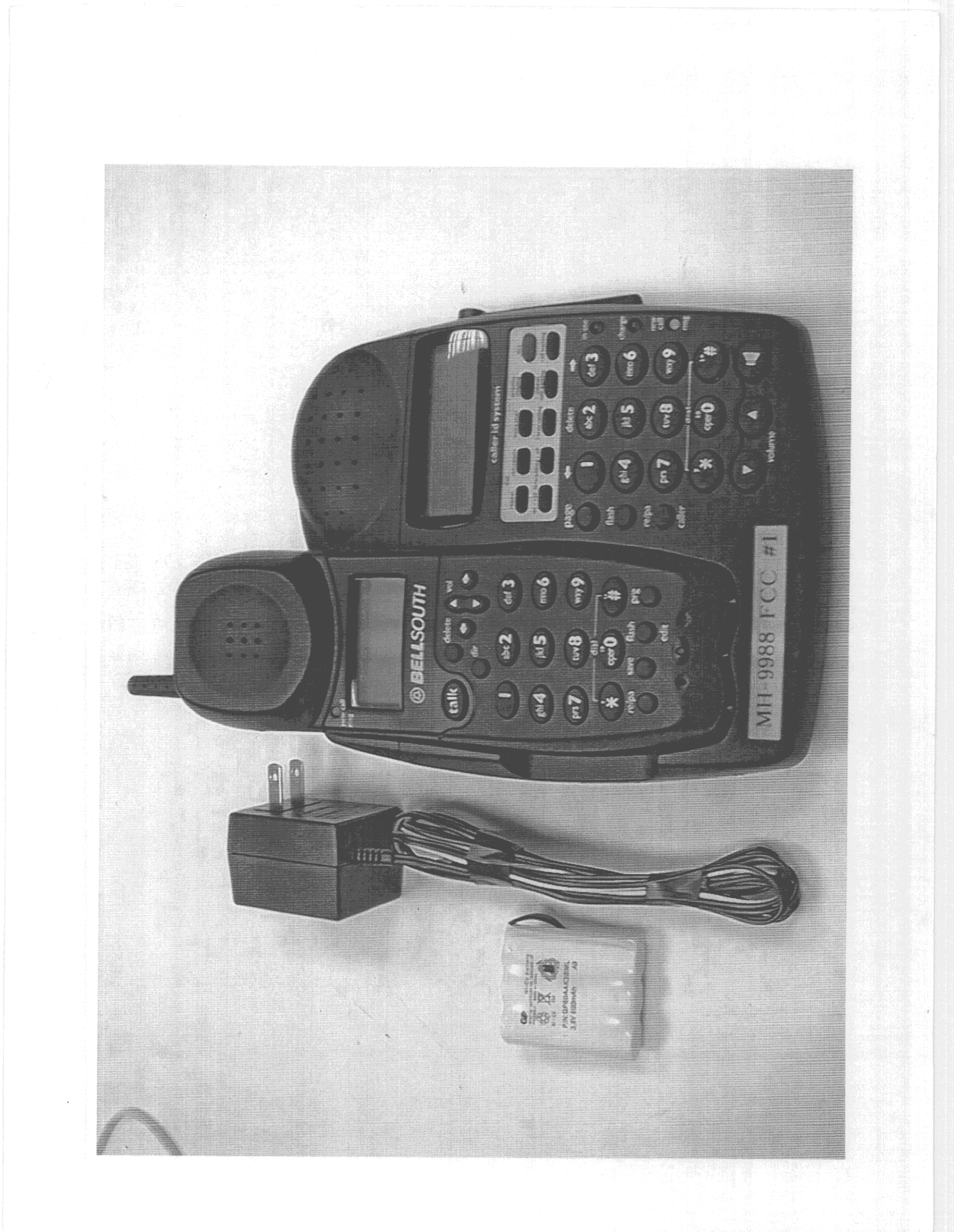
DK4MH9988BK
Oct 19, 1999Cordless Phone
Equipment Class
DSS - Part 15 Spread Spectrum Transmitter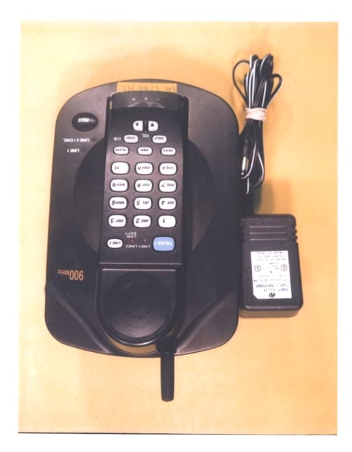
DK4CT910
Sep 30, 1999900 MHz Cordless Telephone
Equipment Class
ETS - Part 15 Cordless Telephone System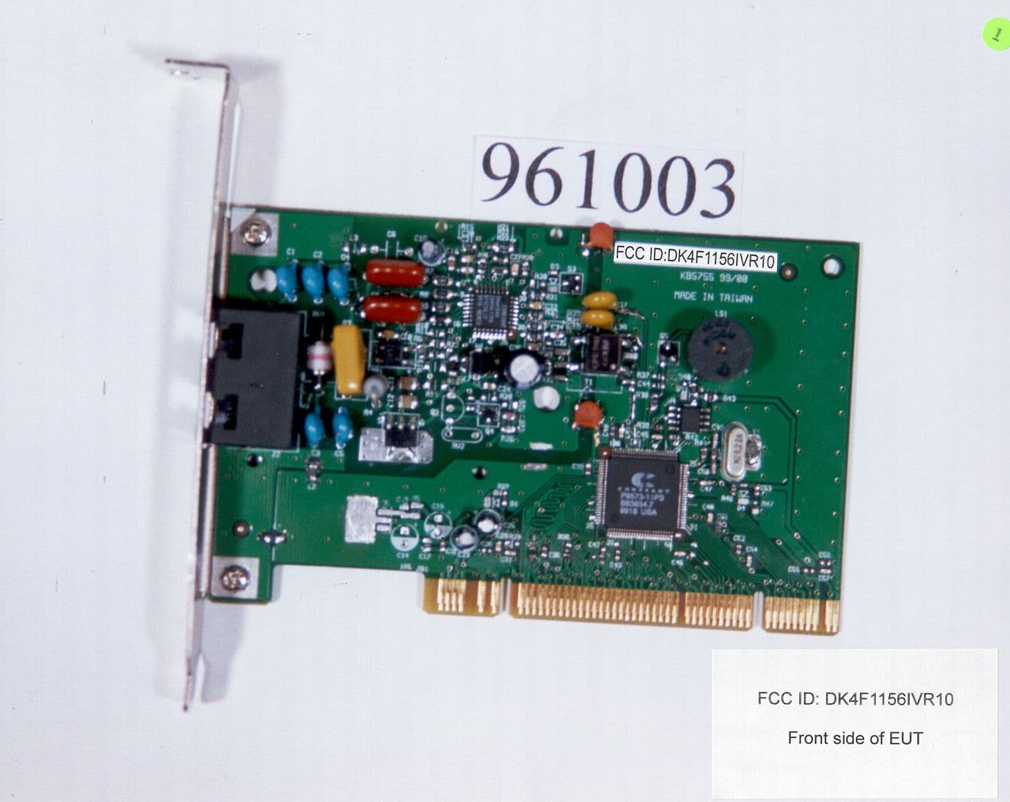
DK4F1156IVR10
Aug 10, 1999Data Fax Modem
Equipment Class
JBC - Part 15 Class B Computing Device/Personal Computer