DK4SF1156IVR6Modem Card
GVC Corporation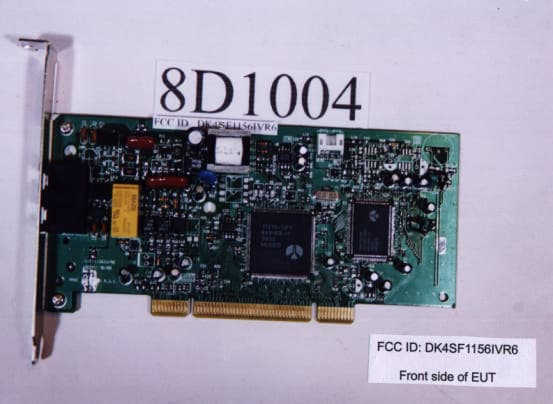
Click to zoom
Application Details
- Equipment Class
- JBP - Part 15 Class B Computing Device Peripheral
- Date of Grant
- Feb 10, 1999
- Application Purpose
- Original Equipment
- Date of Application
- Dec 30, 1998
- Equipment Note
- Modem Card
- Company
- GVC Corporation
- Country
- Taiwan
Documents & Files
Document Text
Text extracted from the exhibit documents filed with the FCC. Open a document above to read the original.
Users Manual
High Performance V.90/K56flex/V.34+/V.42bis 56000BPS Plug & Play Internal Data/Fax/Voice Modem User's Manual Contents Section One - Introduction ........................... 1 Section Two - Installation Guide .................. 1 Section Three - AT Command Set ............... 5 Section Four - S Registers........................10 Appendix A Specifications ........................ 10 Appendix B Installations ..........................11 (S)F-1156IV/R6 The information contained in this manual has been validated at the time of this manual's production. The manufacturer reserves the right to make any changes and improvements in the product de- scribed in this manual at any time and without notice. Consequently the manufacturer assumes no liability for damages incurred directly or indi- rectly from errors, omissions or discrepancies be- tween the product and the manual. All registered trademarks are the property of their respective owners. Copyright © 1997 All rights reserved. No reproduction of this document in any form is permitted without prior written authorization from the Manufacturer. 1 1.Turn off power to Windows 98 PC, remove PC cover, insert card to an available PCI slot,close cover,turn on power. 2.When Windows 98 loads,it will detect the new hard- ware and ask for a driver. the following window should appear. 3.Click OK and you should see: Section One - Introduction This 56 kbps* Plug and Play FAX/Data Modem connects your computer to all popular high speed mo- dems available today. Its incorporates "V.90/K56Flex" (56Kbps) technology to provide increased download speeds using regular telephone lines. The modem incor- porates Plug and Play for ease of installation. This manual describes the AT commands and S- registers so that your system can be customized for a particular operating environment. *Note: K56flex is capable of downloading at 56kbps. However, current FCC regulations limit its speeds to 53Kbps. Section Two - Installation Guide 2 4.Select "Search for the best driver for your device" Option. Click Next and you should see: 5.Insert the CD-ROM that comes with your Modem into the CD-ROM drive. Make sure the CD-ROM drive check box is checked. Leave all other check boxes blank. Click Next and you should see: 3 6.Click Next and you should see the following. 7.Wait until Windows 98 finishes copying all the required files. 4 8.When you see the above windows, Windows 98 has already finished copying all the files. Click Finish and you should see the following window. 9.Your Modem is now installed in Windows 98. 5 Section Three - AT Command Set 3.1 Commands Commands are accepted by the modem while it is in Command Mode. Your modem is automatically in Com- mand Mode until you dial a number and establish a connection. Commands may be sent to your modem from a PC running communication software or any other terminal devices. Your modem is capable of data communication at rates of: 300, 1200, 2400, 4800, 9600, 14400, 19200, 28800, 38400, 57600, and 115200 bps. Make sure your COM port baud rate settings in your communications software is set to one of the above speeds. 3.2 Command Structure All commands sent to the modem must begin with AT and end with ENTER. All commands may be typed in either upper or lower case, but not mixed. To make the command line more readable, spaces may be inserted between commands. If you omit a parameter from a command that requires one, it is just like specifying a parameter of 0. Example: ATH [ENTER] This command causes your modem to hang up. 3.3 Basic AT Commands In the following listings, all default settings are printed in bold text. CommandFunction AManually answer incoming call. A/Repeat last command executed. Do not precede A/ with AT or follow with ENTER. D_0 - 9, A-D, # and * Llast number redial Ppulse dialing Ttouch-tone dialing Wwait for second dial tone ,pause @wait for five seconds of silence 6 !flash ;return to Command Mode after dialing E_E0Commands are not echoed E1Commands are echoed +++Escape Characters Switch from Data Mode to Command Mode H_H0Force modem on-hook (hang up) H1Force modem off-hook (make busy) I_I0Reports product code I1Reports Pre-Computed checksum I2Reports Firmware Version I3Reports OEM defined string I4Reports data pump model and internal code revision L_L0Low speaker volume L1Low speaker volume L2Medium speaker volume L3High speaker volume M_M0Internal speaker off M1Internal speaker on until carrier detected M2Internal speaker always on M3Internal speaker on until carrier detected and off while dialing O_O0Return to Data Mode O1Return to Data Mode and initiate an equalizer retrain PSet Pulse dial as default Q_Q0Modem sends responses Q1Modem does not send responses Sr?Read and display value in register r. Sr=nSet register r to value n (n = 0-255). TSet Tone Dial as default V_V0Numeric responses V1Word responses X_X0Hayes Smartmodem 300 compatible responses/blind dialing. X1Same as X0 plus all CONNECT responses/ blind dialing X2Same as X1 plus dial tone detection X3Same as X1 plus busy detection/blind dialing 7 X4All responses and dial tone and busy signal detection Z_Z0Reset and retrieve active profile 0 3.4 Extended AT Commands &C_&C0Force Carrier Detect Signal High (ON) &C1 Turn on CD when remote carrier is present &D_&D0Modem ignores the DTR signal &D1Modem returns to Command Mode after DTR toggle &D2 Modem hangs up, returns to the Command Mode after DTR toggle &F_&FRecall factory default configuration &G_&G0 Guard tone disabled &G1Guard tone disabled &G21800 Hz guard tone &P_&P1Select 33 ratio M/B at 10pps &P3Same as &P1 setting but at 20 pulses per second &V&V0Displays Active and Stored Profiles &W_&W0 Stores the active profile as Profile 0 %E_%E0 Disable auto-retrain %E1 Enable auto-retrain +MS?Displays the current Select Modulation settings +MS=?Displays a list of supported Select Modulation options +MS=a,b,c,d,e,fSelect modulation. a,b,c,d,e,f default=V.90,1,75,33600, 75,56000.Parameter¡§a¡ ̈specifies the modulation …
Text truncated - open the document above for the full version.
Block Diagram
PCI Connector to Host System 11235 PCI Interface Chipset 6789 Codec DAA Speakerphone Interface Crystal28.224Mh z To Line To Sound Card (S)F1156-IV/R6Block Diagram
ID Label/Location Info
QC PASSED 2R 32+-0.3 MODEL:F-1114HV/R15 FCC ID :DK4VF1114HVR12 MADE IN TAIWAN Power Rating:5Vdc,300mA 7 THIS DEVICE COMPLIES WITH PART 15 & 68 FCC RULES. FCC REG. NO.:DK4XXX-XXXXX-XX-X REN:XXX USOC:RJ11C OPERATION IS SUBJECT TO THE FOLLOWING TWO CONDITIONS: (1) THIS DEVICE MAY NOT CAUSE HARMFUL INTERFERENCE. (2) THIS DEVICE MUST ACCEPT ANY INTERFERENCE RECEIVED INCLUDING INTERFERENCE THAT MAY CAUSE UNDESIRED OPERATION. THE CLASS B DIGITAL APPARATUS MEETS ALL REQUIREMENTS OF THE CANADIAN INTERFERENCE-CAUSING EQUIPMENT REGULATIONS. CET APPAREIL NUMERIQUE DE LA CLASSES B RESPECTE TOUTES LES EXIGENCES DU REGLEMENT SUR LE MATERIEL BROUILLEUR DU CANADA. XX MODEL:(S)F-1156IV/R6 FCC ID:DK4SF1156IVR6 MADE IN TAIWAN 38+-0.3 ½Ð ¥[ ¤W ¼t °Ó ¥N ½X QC PASSED QC PASSED This device complies with Canada ICES-003, Class B RR C
Test Report
FCC TEST REPORT REPORT NO. : F8D1004 SPORTON International Inc. FCC ID : DK4SF1156IVR6 TEL: 886-2-2696-2468ISSUED DATE:Dec. 16, 1998 FAX: 886-2-2696-2255PAGE NUMBER: 1 OF 22 FCC TEST REPORT for CISPR PUB. 22 CLASS B Equipment : Voice / Fax / Data Modem Card MODEL NO. : SF-1156IV/R6 FCC ID : DK4SF1156IVR6 Filing Type : Original Grant Applicant: GVC CORPORATION 14F, No. 76, Tun-Hwa S. Rd., Sec. 2, Taipei, Taiwan, R.O.C. ! The test result refers exclusively to the test presented test model / sample. ! Without the written authorization of the test lab., the Test Report may not be copied. SPORTON INTERNATIONAL INC. 6F, No. 106, Sec. 1, Hsin Tai Wu Rd., Hsi Chih, Taipei Hsien, Taiwan, R.O.C. FCC TEST REPORT REPORT NO. : F8D1004 SPORTON International Inc. FCC ID : DK4SF1156IVR6 TEL: 886-2-2696-2468ISSUED DATE:Dec. 16, 1998 FAX: 886-2-2696-2255PAGE NUMBER: 2 OF 22 TABLE OF CONTENT SECTION TITLEPAGE CERTIFICATE OF COMPLIANCE................................................................................................................................3 1. GENERAL DESCRIPTION OF EQUIPMENT UNDER TEST ................................................................................4 1.1. APPLICANT..........................................................................................................................................................................................................4 1.2. MANUFACTURER...............................................................................................................................................................................................4 1.3. BASIC DESCRIPTION OF EQUIPMENT UNDER TEST ...................................................................................................................................4 1.4. FEATURE OF EQUIPMENT UNDER TEST .......................................................................................................................................................4 2. TEST CONFIGURATION OF EQUIPMENT UNDER TEST...................................................................................5 2.1. TEST MANNER....................................................................................................................................................................................................5 2.2. DESCRIPTION OF TEST SYSTEM .....................................................................................................................................................................5 2.3. CONNECTION DIAGRAM OF TEST SYSTEM .................................................................................................................................................7 3. TEST SOFTWARE ........................................................................................................................................................8 4. GENERAL INFORMATION OF TEST ......................................................................................................................9 4.1. TEST FACILITY ...................................................................................................................................................................................................9 4.2. STANDARD FOR METHODS OF MEASUREMENT ........................................................................................................................................9 4.3 .TEST IN COMPLIANCE WITH ...........................................................................................................................................................................9 4.4. FREQUENCY RANGE INVESTIGATED ............................................................................................................................................................9 4.5. TEST DISTANCE .................................................................................................................................................................................................9 5. TEST OF CONDUCTED POWERLINE ...................................................................................................................10 5.1. MAJOR MEASURING INSTRUMENTS ...........................................................................................................................................................10 5.2. TEST PROCEDURES .........................................................................................................................................................................................11 5.3. TYPICAL TEST SETUP LAYOUT OF CONDUCTED POWERLINE ..............................................................................................................12 5.4. TEST RESULT OF AC POWERLINE CONDUCTED EMISSION....................................................................................................................13 5.5. PHOTOGRAPHS OF CONDUCTED POWERLINE TEST CONFIGURATION ...............................................................................................14 6. TEST OF RADIATED EMISSION.............................................................................................................................16 6.1. MAJOR MEASURING INSTRUMENTS ...........................................................................................................................................................16 6.2. TEST PROCEDURES .........................................................................................................................................................................................17 6.3. TYPICAL TEST SETUP LAYOUT OF RADIATED EMISSION.......................................................................................................................18 6.4. TEST RESULT OF RADIATED EMISSION ......................................................................................................................................................…
Text truncated - open the document above for the full version.
Contact Information
Applicant
T. C. Wu(Manager)
886 3 328-7799Fax: 886 3 397-7598
Technical Contact
SPORTON International Inc.Kathy Lin
[email protected]886-2-2696-2468
6F, No. 106, Sec. 1, Hsin Tai Wu Rd., Hsi Chin, · Taiwan
Non-Technical Contact
SPORTON International Inc.Kathy Lin
[email protected]718-468-4260
Test Firm
Sporton International Inc.W. Huang
Technical Specifications
| # | Rule Parts | Frequency Range | Power Output |
|---|---|---|---|
| 1 | 15B | - | - |
Other Applications from GVC Corporation
DK4MH9082
Oct 27, 1999DSS - Part 15 Spread Spectrum Transmitter
Equipment Class
DSS - Part 15 Spread Spectrum Transmitter
DK4GH2400
Oct 25, 1999Cordless Telephone
Equipment Class
DXT - Part 15 Low Power Transceiver, Rx Verified
DK4MH9988BK
Oct 19, 1999Cordless Phone
Equipment Class
DSS - Part 15 Spread Spectrum Transmitter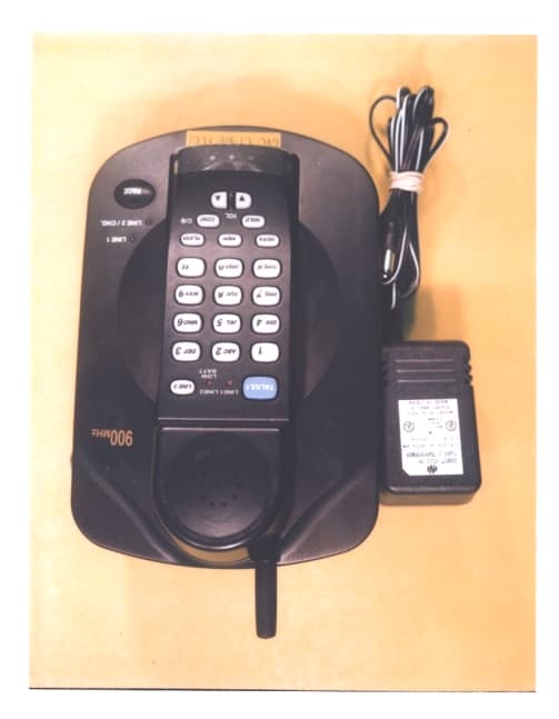
DK4CT910
Sep 30, 1999900 MHz Cordless Telephone
Equipment Class
ETS - Part 15 Cordless Telephone System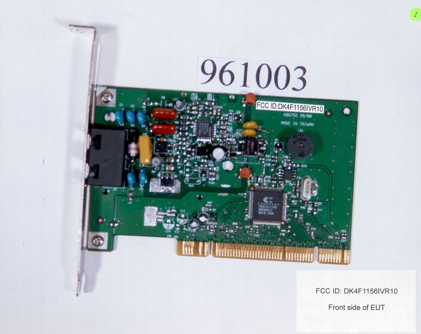
DK4F1156IVR10
Aug 10, 1999Data Fax Modem
Equipment Class
JBC - Part 15 Class B Computing Device/Personal Computer