DKNCR90802.11ac Client STB
DISH Technologies L.L.C.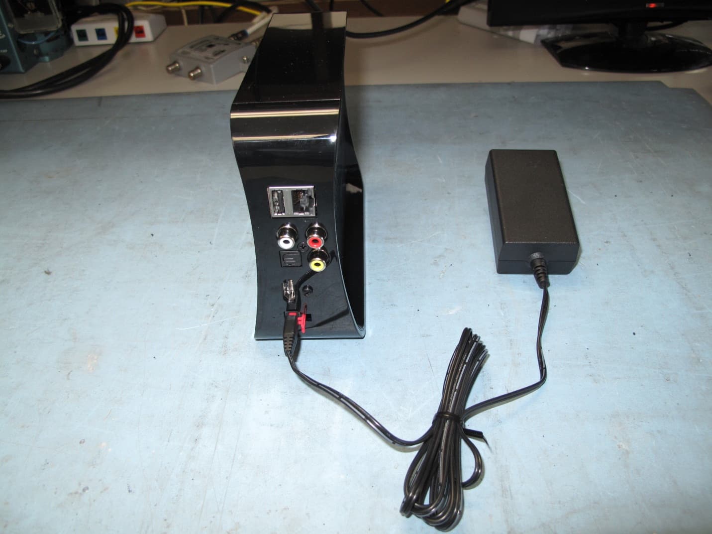
Click to zoom
Application Details
- Equipment Class
- NII - Unlicensed National Information Infrastructure TX
- Date of Grant
- Feb 13, 2014
- Application Purpose
- Original Equipment
- Date of Application
- Feb 13, 2014
- Equipment Note
- 802.11ac Client STB
- Frequency Range
- 5500.00000000 - 5720.00000000
- Company
- DISH Technologies L.L.C.
- Country
- United States
Documents & Files
Document Text
Text extracted from the exhibit documents filed with the FCC. Open a document above to read the original.
Users Manual
Wireless Joey GETTING STARTED GUIDE Warning and Attention Symbols You must be aware of safety when you install and use this system. This Wireless Joey Getting Started Guide provides various procedures. If you do some of these procedures carelessly, you could injure or kill yourself or damage equipment or property. Some other procedures require special attention. The lightning flash with arrowhead symbol, within an equilateral triangle, is intended to alert the user to the presence of uninsulated “dangerous voltage” within the product’s enclosure that may be of sufficient magnitude to constitute a risk of electric shock to persons . The exclamation point within an equilateral triangle is intended to alert the user to the presence of important operating and maintenance (servicing) instructions in the literature accompanying the appliance . The Class II equipment symbol means the equipment has additional insulation and does not need to be grounded . For Your Safety Warning: Do not try to open the case of the Wireless Joey™ receiver. There is risk of electrical shock, which may cause damage to the Wireless Joey and/or personal injury or death to you. There are no user-serviceable parts inside the Wireless Joey receiver. Opening the receiver’s case or making unauthorized changes will void the warranty. Warning: To reduce the risk of fire or electric shock, do not expose this appliance to rain or moisture. Important Software Notice As with all software controlled products, unexpected behavior could arise if the user tries to perform operations in a non-routine manner. This product, like almost any other high tech product, is subject to bugs and hence EchoStar CANNOT AND DOES NOT GUARANTEE OR WARRANT THAT ALL FEATURES, SUCH AS PARENTAL CONTROLS, WILL WORK AS INTENDED UNDER ALL CIRCUMSTANCES. EchoStar endeavors to improve such conditions and will periodically download improvements. i Equipment and Software Covered by this User Guide This Wireless Joey Getting Started Guide covers the Wireless Joey™ receiver and software models Wireless Joey. This Wireless Joey Getting Started Guide may cover other devices not listed here. Publishing Information Copyright © 2014. EchoStar Technologies L.L.C., Englewood, Colorado 80112. All rights reserved. The information in this Wireless Joey Getting Started Guide may change without notice. Revisions may be issued to tell you about such changes. Send comments or questions about this Wireless Joey Getting Started Guide to [email protected] or Technical Publications, EchoStar Technologies L.L.C, 90 Inverness Drive Circle East, Englewood, Colorado 80112. DISH is a registered trademark of DISH Network L.L.C. All product names, trade names, or corporate names mentioned in this Wireless Joey Getting Started Guide are acknowledged to be the proprietary property of the registered owners. Manufactured under license from Dolby Laboratories. Dolby and the double-D symbol are trademarks of Dolby Laboratories. ® HDMI, the HDMI logo and High-Definition Multimedia Interface are trademarks or registered trademarks of HDMI Licensing LLC. This equipment may incorporate copyright protection technology that is protected by U.S. patents, patent applications, and/or other intellectual property rights. Use of such copyright protection technology is intended for home and other limited pay-per-view uses only unless otherwise authorized. Reverse engineering or disassembly is prohibited. ii 1 Read these instructions. 2 Keep these instructions. 3 Heed all warnings. 4 Follow all instructions. 5 Do not use the apparatus near water. 6 Clean only with a dry cloth. 7 Do not block any ventilation openings. Install in accordance with the manufacturer’s instructions. 8 Do not install near any heat sources such as radiators, heat registers, stoves, or other apparatus (including amplifiers) that produce heat. 9 Do not defeat the safety purpose of the polarized or grounding-type plug. A polarized plug has two blades with one wider than the other. A grounding-type plug has two blades and a third grounding prong. The wide blade or the third prong are provided for your safety. If the provided plug does not fit into your outlet, consult an electrician for replacement of the obsolete outlet. 10 Protect the power cord from being walked on or pinched, particularly at plugs, convenience receptacles, and the point where they exit from the apparatus. 11 Only use attachments/accessories specified by the manufacturer. 12 Unplug the apparatus during lightning storms or when unused for long periods of time. 13 Refer all servicing to qualified service personnel. Servicing is required when the apparatus has been damaged in any way, such as the power supply cord or plug is damaged, liquid has been spilled or objects have fallen into it, the apparatus has been exposed to rain or moisture, does not operate normally, or has been dropped. 14 The power plug must be readily accessible so that the apparatus can be easily disconnected from the AC power. 15 The Wireless Joey™ receiver is still connected to the AC power whenever it is plugged into a live power outlet, even if it is turned off using the remote control or front panel buttons. 16 No flame sources, such as lit candles, should be placed on the equipment. 17 The apparatus shall not be exposed to dripping or splashing, and no objects filled with liquids, such as vases, shall be placed on the top of it. 18 Use only the power supply provided with the receiver. Unplug the receiver’s power cord by gripping the power plug, not the cord. 19 Do not overload wall outlets or extension cords; this can result in a risk of fire or electrical shock. Important Safety Instructions iii Important Safety Instructions, continued 20 Never insert objects of any kind into the receiver through openings, as the objects may touch dangerous voltage points or short out parts. This could cause fire or electrical shock. 21 Do not locate the antenna near overhead light or power circuits, or w…
Text truncated - open the document above for the full version.
Attestation Statements
EchoStar Technologies L.L.C. 90 Inverness Circle East Englewood, CO 80112 (303) 706-5234 February 4, 2014 Federal Communications Commission 7435 Oakland Mills Road Columbia, MD 21046 RE: DKNCR90 To Whom It May Concern: The ID:072 client software and associated drivers: will not initiate any transmission on DFS frequencies without initiation by a master device will not transmit beacons on DFS frequencies/channels do not support ad-hoc or peer to peer networks Sincerely, Ian Schroeder Regulatory Compliance Engineer EchoStar Technologies L.L.C.
Attestation Statements
EchoStar Technologies L.L.C. 90 Inverness Circle East Englewood, CO 80112 (303) 706-5234 February 10, 2014 Federal Communications Commission 7435 Oakland Mills Road Columbia, MD 21046 RE: DKNCR90 To Whom It May Concern: The ID:072 product is a 802.11a/n/ac client device only. Users and installers do not have access to nor can they configure the SW within the product. We as the manufacturer maintain sole ability to modify the internal SW and will maintain compliance with the original grant when doing so. SW updates to the product occur using an encrypted data transfer between a master device and the product. The process is initiated and controlled by Echostar at all times. At no time is the user able to access, view, store, delete, or modify the SW data package. SW data files are checked for specific Echostar authenticity within the product and then loaded upon the next power cycle of the product. The users and installers do not have access to change any functions of the device that would place it in an operational mode outside of the FCC grant limits/bands. Sincerely, Ian Schroeder Regulatory Compliance Engineer EchoStar Technologies L.L.C.
Attestation Statements
EchoStar Technologies L.L.C. 90 Inverness Circle East Englewood, CO 80112 (303) 706-5234 January 13, 2014 Federal Communications Commission 7435 Oakland Mills Road Columbia, MD 21046 RE: DKNCR90 To Whom It May Concern: Other portions of the product not related to the radio circuit are tested to and comply with the FCC’s Verification Authorization procedure. Sincerely, Ian Schroeder Regulatory Compliance Engineer EchoStar Technologies L.L.C.
Cover Letter(s)
Echostar Technologies L.L.C. 90 Inverness Circle East Englewood, CO 80112 (303) 706-5234 October 7, 2013 UL LLC Certification Division 47173 Benicia Street Fremont, CA 94538, USA To whom it may concern: I, the undersigned, hereby authorize UL LLC to act on our behalf in all manners relating to application for equipment authorization, including signing of all documents relating to these matters. Any and all acts carried out by UL LLC on our behalf shall have the same effect as acts of our own. I, the undersigned, hereby certify that we are not subject to a denial of federal benefits, that includes FCC benefits, pursuant to Section 5301 of the Anti-Drug Abuse Act of 1988, 21 U.S.C. 853(a). In authorizing UL LLC as our agent, we still recognize that we are responsible to: a) comply with the relevant provisions of the certification program; b) make all necessary arrangements for the conduct of the evaluation, including provision for examining documentation and access to all areas, records (including internal audit reports) and personnel for the purposes of evaluation (e.g. testing, inspection, assessment, surveillance, reassessment) and resolution of complaints; c) make claims regarding certification only in respect of the scope for which certification has been granted; d) do not use our product certification in such a manner as to bring the Certification Division into disrepute and not make any statement regarding our product certification which the Certification Division may consider misleading or unauthorized; e) upon suspension or cancellation of certification, discontinue use of all advertising matter that contains any reference thereto and return any certification documents as required by the Certification Division; f) use certification only to indicate the products are certified as being in conformity with specified standards; Echostar Technologies L.L.C. 90 Inverness Circle East Englewood, CO 80112 (303) 706-5234 g) endeavor to ensure that no certificate or report nor any part thereof is used in a misleading manner; h) ensure that any reference to our product certification in communication media such as documents, brochures or advertising, complies with the requirements of the Certification Division; i) keep a record of all complaints made known to the us relating to the product’s compliance with requirements of the relevant standard and to make these records available to the Certification Division when requested; j) take appropriate action with respect to such complaints and any deficiencies found in products or services that affect compliance with the requirements for certification; k) document the actions taken. This authorization is valid until further written notice from the applicant. Sincerely Yours, Ian Schroeder Regulatory Compliance Engineer Echostar Technologies L.L.C.
Cover Letter(s)
1(2) EchoStar Technologies L.L.C. 90 Inverness Circle East Englewood, CO 80112 (303) 706-5234 Attention: Application Examiner Re: Request for confidentiality Applicant: Echostar Technologies L.L.C. FCC ID: DKNCR90 To whom it may concern, Permanent Confidentiality Request is hereby submitted by Echostar Technologies L.L.C. to withhold permanently from public review certain portions of the application for equipment certification for the referenced FCC identifiers. This request for confidentiality is made pursuant to 47 CFR 0.457(d) and 0.459 of the FCC Rules. In particular, the following sections of the application are to be kept permanently confidential: Schematics Block diagrams Operational Description Tune up procedure Parts lists Short-term Confidentiality Request is hereby submitted by Echostar Technologies L.L.C. to withhold from public review for a period of 180 days from the date of the Grant of Equipment Authorization and prior to marketing, certain portions of the application for equipment certification for the referenced FCC identifiers. This request for confidentiality is made pursuant to 47 CFR 0.457(d) and 0.459 of the FCC Rules. In particular, the following sections of the application are to be kept confidential for a period of 180 days from the date of Authorization: Test setup photos External photos Internal photos User manual Rationale for request for confidentiality: Echostar Technologies L.L.C. has invested considerable time and materials in research and development to produce the referenced product. Permanent confidentiality: Disclosure of the permanently confidential portions of this application to competitors would not only give them significant competitive advantages in developing similar products, but would also disclose successful implementation of unpublished, leading edge technology developed by us. 2(2) Short term confidentiality: Disclosure of the short-term confidential portions of this application during the period of importation and/or distribution would reveal key aspects of proprietary technology to competitors and diminish the value of our investment in research and development. If you have questions or need further information, please contact the undersigned. Sincerely, Ian Schroeder Regulatory Compliance Engineer Echostar Technologies L.L.C.
ID Label/Location Info
FCC Label Location
ID Label/Location Info
This device complies with part 15 of the FCC Rules. Operation is subject to the following two conditions:(1) this device may not cause harmful interference, and (2) this device must accept any interference received, including interference that may cause undesired operation. See applicable patents at www.echostar.com/ip Manufactured under license from Dolby Laboratories. Dolby and the double-D symbol are trademarks of Dolby Laboratories. Model: Wireless JoeyREG ID:072 FCC ID: DKNCR90
Operational Description
Frequency (GHz) Peak Gain (dB) 4.8001.53 4.8151.57 4.8301.64 4.8451.62 4.8601.51 4.8751.52 4.8901.36 4.9051.56 4.9201.57 4.9351.65 4.9501.37 4.9651.37 4.9801.29 4.9951.57 5.0101.59 5.0251.66 5.0401.62 5.0551.67 5.0701.56 5.0851.79 5.1001.77 5.1152.01 5.1301.81 5.1451.82 5.1601.73 5.1751.97 5.1901.87 5.2052.25 5.2202.13 5.2352.23 5.2502.34 5.2652.40 5.2802.35 5.2952.31 5.3102.23 5.3252.31 5.3402.24 5.3552.10 5.3702.31 5.3852.29 5.4002.39 5.4152.33 5.4302.31 5.4452.17 5.4602.23 5.4752.33 5.4902.26 5.5052.34 5.5202.47 5.5352.43 5.5502.48 5.5652.53 5.5802.48 5.5952.33 5.6102.57 5.6252.67 5.6402.82 5.6552.79 5.6702.69 5.6852.61 5.7002.70 5.7152.84 5.7303.00 5.7453.16 5.7602.86 5.7752.84 5.7902.81 5.8052.86 5.8202.90 5.8352.89 5.8502.98 5.8652.92 5.8802.98 5.8952.82 5.9102.92 5.9252.82 5.9402.91 5.9552.95 5.9702.76 5.9852.81 6.0002.70
Operational Description
Proprietary and Confidential Airgain, Inc. Page 1 Patent Protected Revision B 14 June 2012 Doc. # 247-02-00-001-1 Airgain Embedded Antenna Product Datasheet Profile520B Model N5x20B Series 1930 Palomar Point Way, Suite 107 Carlsbad, CA 92008 Tel: +1 760 579 0200 Fax: +1 760 579 0892 Information: [email protected] Sales: [email protected] Support: [email protected] Coverage. Performance. Smart. Model N5X20B Product Datasheet Proprietary and Confidential Airgain, Inc. Page 2 Patent Protected Revision B 14 June 2012 Doc. # 247-02-00-001-1 Coverage. Performance. Smart. Revision history Revision Date Note 247-02-00-001-1 Rev A March 14, 2012 Initial Draft 247-02-00-001-1 Rev B June 14, 2012 Update PN Information Model N5X20B Product Datasheet Proprietary and Confidential Airgain, Inc. Page 3 Patent Protected Revision B 14 June 2012 Doc. # 247-02-00-001-1 Coverage. Performance. Smart. Table of Contents 1. Model N5x20B Embedded Antenna ........................................................................................ 4 2. Features .................................................................................................................................... 4 3. Specification and Interface ...................................................................................................... 5 4. Radiation Patterns .................................................................................................................... 5 5. Dimensions .............................................................................................................................. 6 6. ROHS ....................................................................................................................................... 7 7. Mounting Guidelines ............................................................................................................... 7 8. Supporting Documents............................................................................................................. 9 9. Feature and Options Information ............................................................................................. 9 9.1. Pre-applied Mounting Tape Information ............................................................................ 10 9.2. Part Number Information ................................................................................................... 10 Disclaimers The information in this document is provided in connection with Airgain Antenna products and is proprietary and confidential. Airgain may make changes at anytime without notice. Please verify with Airgain before finalizing a product design. Model N5X20B Product Datasheet Proprietary and Confidential Airgain, Inc. Page 4 Patent Protected Revision B 14 June 2012 Doc. # 247-02-00-001-1 Coverage. Performance. Smart. 1. Model N5x20B Embedded Antenna Based on Airgain’s patented technology, the Model N5x20B Embedded Antenna provides a high efficiency, 5GHz band embedded antenna solution for Wi-Fi and ISM band applications, such as WLAN products. As embedded antenna solutions become the focus of next generation wireless product design, the Model N5x20B provides the flexibility of an embedded antenna with top performance. The Model N5x20B Embedded Antenna has a smaller footprint than the model N5X20SC making it better suited for tight spaces. It is designed to accommodate most WLAN access point applications, such as routers and gateways and can be easily integrated into an ID package design. 2. Features The Model N5x20B Embedded Antenna is defined by the following features: IEEE 802.11 a/n standards Single 5GHz Band operation Case mount 1.7 dbi peak gain @ 5.2 GHz High efficiency Quick integration Figure 1 Model N5x20B-T Embedded Antenna with pre-applied mounting tape Model N5X20B Product Datasheet Proprietary and Confidential Airgain, Inc. Page 5 Patent Protected Revision B 14 June 2012 Doc. # 247-02-00-001-1 Coverage. Performance. Smart. 3. Specification and Interface Standard IEEE 802.11n and 802.11 a Frequency Range 4.9 to 5.9 GHz Peak Gain 1.7 dbi @ 5.2 GHz VSWR 2:1 Feed Impedance 50 Ohms Power Handling 30 dBm Interface 50 ohm, 1.13mm diameter, micro coax cable (available with optional U.FL compatible cable connector and/or cable mounted EMI ferrites) Antenna Dimensions 17.5 x 9.8 x 0.8 (mm) Weight 0.5 g (0.01 oz) Temperature Range Operating : -40° C to +75° C (-40° F to +167° F) Storage: -40° C to +85° C (-40° F to +185° F) Humidity Range 0% to 95% non-condensing 4. Radiation Patterns Radiation patterns for the Model N5x20B were taken with the antenna mounted on a 90mm by 90mm by 2.2mm thick, ABS plastic sheet using 1.6mm double sided tape. Figure 2 Model N5x20B Measurement axes Figure 3a Model N5x20B Measured Radiation Patterns at 5.2 GHz Model N5X20B Product Datasheet Proprietary and Confidential Airgain, Inc. Page 6 Patent Protected Revision B 14 June 2012 Doc. # 247-02-00-001-1 Coverage. Performance. Smart. Figure 3b Model N5x20B Measured Radiation Patterns at 5.2 GHz 5. Dimensions Figure 4 Model N5x20B Embedded Antenna Dimensions Model N5x20B-T Pre-applied Tape Dimensions Model N5X20B Product Datasheet Proprietary and Confidential Airgain, Inc. Page 7 Patent Protected Revision B 14 June 2012 Doc. # 247-02-00-001-1 Coverage. Performance. Smart. 6. ROHS Model N5x20B Embedded Antennas are RoHS compliant. 7. Mounting Guidelines The model N5x20B embedded antenna can be simply mounted on the interior of an ABS Plastic case using double sided adhesive tape. This can simplify the industrial design process and can also shorten the product development cycle. The N5x20B is mildly loaded (detuned) if it is not properly spaced away from the ABS Plastic mounting surface. Airgain recommends mounting the N5x20B antenna onto a 2.2mm thick ABS Plastic case with 1.6mm double sided tape for optimum performance. Mounting the N5x20B to case walls of different thicknesses may be considered, but optimum separation between the …
Text truncated - open the document above for the full version.
RF Exposure Info
FCC Part 1 Subpart I FCC Part 2 Subpart J RF EXPOSURE REPORT FOR 802.11ac 3x3 Set Top Box Client with RF4CE for remote operation MODEL NUMBER: ID:072 FCC ID: DKNCR90 REPORT NUMBER: 13U16571-3 ISSUE DATE: January 28, 2014 Prepared for ECHOSTAR 90 INVERNESS CIRCLE EAST ENGLEWOOD, CO 80112, U.S.A. Prepared by UL VERIFICATION SERVICES INC. 47173 BENICIA STREET FREMONT, CA 94538, U.S.A. TEL: (510) 771-1000 FAX: (510) 661-0888 REPORT NO: 13U16571-3 DATE: JANUARY 28, 2014 EUT: 802.11ac 3x3 Set Top Box Client with RF4CE for remote operation FCC ID: DKNCB1138 Page 2 of 11 UL VERIFICATION SERVICES INC. FORM NO: CCSUP4701I 47173 BENICIA STREET, FREMONT, CA 94538, USA TEL: (510) 771-1000 FAX: (510) 661-0888 This report shall not be reproduced except in full, without the written approval of . UL Verification Services Inc. Revision History Rev. Issue Date Revisions Revised By -- 01/28/14 Initial Issue F. de Anda REPORT NO: 13U16571-3 DATE: JANUARY 28, 2014 EUT: 802.11ac 3x3 Set Top Box Client with RF4CE for remote operation FCC ID: DKNCB1138 Page 3 of 11 UL VERIFICATION SERVICES INC. FORM NO: CCSUP4701I 47173 BENICIA STREET, FREMONT, CA 94538, USA TEL: (510) 771-1000 FAX: (510) 661-0888 This report shall not be reproduced except in full, without the written approval of . UL Verification Services Inc. TABLE OF CONTENTS 1. ATTESTATION OF TEST RESULTS ................................................................................. 4 2. TEST METHODOLOGY ..................................................................................................... 5 3. REFERENCES ................................................................................................................... 5 4. FACILITIES AND ACCREDITATION ................................................................................. 5 5. MAXIMUM PERMISSIBLE RF EXPOSURE ....................................................................... 6 5.1. FCC RULES ................................................................................................................ 6 5.2. EQUATIONS ................................................................................................................ 7 5.3. LIMITS ......................................................................................................................... 9 6. RF EXPOSURE RESULTS ................................................................................................10 REPORT NO: 13U16571-3 DATE: JANUARY 28, 2014 EUT: 802.11ac 3x3 Set Top Box Client with RF4CE for remote operation FCC ID: DKNCB1138 Page 4 of 11 UL VERIFICATION SERVICES INC. FORM NO: CCSUP4701I 47173 BENICIA STREET, FREMONT, CA 94538, USA TEL: (510) 771-1000 FAX: (510) 661-0888 This report shall not be reproduced except in full, without the written approval of . UL Verification Services Inc. 1. ATTESTATION OF TEST RESULTS COMPANY NAME: ECHOSTAR CORPORATION 90 INVERNESS CIRCLE EAST ENGLEWOOD, CO 80112, U.S.A. EUT DESCRIPTION: 802.11ac 3x3 Set Top Box Client with RF4CE for remote operation MODEL NUMBER: ID:072 SERIAL NUMBER: P2-224,P2-230, DATE TESTED: DECEMBER 09 – JANUARY 024, 2014 APPLICABLE STANDARDS STANDARD TEST RESULTS FCC PART 1 SUBPART I & PART 2 SUBPART J Pass UL Verification Services Inc. calculated the RF Exposure of the above equipment in accordance with the requirements set forth in the above standards, using test results reported in the test report documents referenced below and/or documentation furnished by the applicant. All indications of Pass/Fail in this report are opinions expressed by UL Verification Services Inc. based on interpretations of these calculations. The results show that the equipment is capable of demonstrating compliance with the requirements as documented in this report. Note: The results documented in this report apply only to the tested sample, under the conditions and modes of operation as described herein. This document may not be altered or revised in any way unless done so by UL Verification Services Inc. and all revisions are duly noted in the revisions section. Any alteration of this document not carried out by UL Verification Services Inc. will constitute fraud and shall nullify the document. This report must not be used by the client to claim product certification, approval, or endorsement by NVLAP, NIST, any agency of the Federal Government, or any agency of any government. Approved & Released For UL Verification Services Inc. By: Calculated By: FRANCISCO DE ANDA FRANCISCO GUARNERO WiSE PROJECT LEAD/ PROGRAM MANAGER LAB TECHNICIAN/ ENGINEER UL Verification Services Inc. UL Verification Services Inc. REPORT NO: 13U16571-3 DATE: JANUARY 28, 2014 EUT: 802.11ac 3x3 Set Top Box Client with RF4CE for remote operation FCC ID: DKNCB1138 Page 5 of 11 UL VERIFICATION SERVICES INC. FORM NO: CCSUP4701I 47173 BENICIA STREET, FREMONT, CA 94538, USA TEL: (510) 771-1000 FAX: (510) 661-0888 This report shall not be reproduced except in full, without the written approval of . UL Verification Services Inc. 2. TEST METHODOLOGY All calculations were made in accordance with FCC OET Bulletin 65 Edition 97-01. 3. REFERENCES All measurements were made as documented in test report 13U16571-4 (RF4CE) UL Verification Services Inc. for operation in the 2.4 GHz band and UL Verification Services Inc. Document 13U16571-1(DTS) and 13U16571-2(UNII) for operation in the 5 GHz bands. Output power, Duty cycle and Antenna gain data is excerpted from the applicable test reports. Antenna gain data is excerpted from product documentation provided by the applicant. 4. FACILITIES AND ACCREDITATION The test sites and measurement facilities used to collect data are located at 47173 Benicia Street, Fremont, California, USA. UL Verification Services Inc. is accredited by NVLAP, Laboratory Code 200065-0. The full scope of accreditation can be viewed at http://ts.nist.gov/standards/scopes/2000650.htm. REPORT NO: 13U16571-3 DATE: JANUARY 28, 2014 EUT: 802.11ac 3x3 Set Top Box Client with RF4CE for …
Text truncated - open the document above for the full version.
Test Report
FCC 47 CFR PART 15 SUBPART E CERTIFICATION TEST REPORT FOR 802.11ac 3x3 Set Top Box Client with RF4CE for remote operation MODEL NUMBER: ID:072 FCC ID: DKNCR90 REPORT NUMBER: 13U16571-2 Revision D ISSUE DATE: February 19, 2014 Prepared for ECHOSTAR 90 INVERNESS CIRCLE EAST ENGLEWOOD, CO 80112, U.S.A. Prepared by UL VERIFICATION SERVICES INC. F47173 BENICIA STREET FREMONT, CA 94538, U.S.A. TEL: (510) 771-1000 FAX: (510) 661-0888 REPORT NO: 13U16571-2D DATE: FEBRUARY 19, 2014 EUT: 802.11ac 3x3 Set Top Box Client with RF4CE for remote operation FCC ID: DKNCR90 Page 2 of 734 UL VERIFICATION SERVICES INC. FORM NO: CCSUP4701J 47173 BENICIA STREET, FREMONT, CA 94538, USA TEL: (510) 771-1000 FAX: (510) 661-0888 This report shall not be reproduced except in full, without the written approval of UL Verification Services Inc. . Revision History Rev. Issue Date Revisions Revised By -- 01/28/14 Initial Issue F. de Anda A 2/11/14 Typographical error corrections on 8.28.4, 8.30.1 and 8.37.3 sections. TCB corrections. F. de Anda B 2/12/14 Updated rule part on pages 257, 267, 278, 418, 434, 453, 480, 500, and 526. F. de Anda C 2/14/14 Added KDB 644545 to documents reference list F. de Anda D 2/19/14 Updated max. power table F. de Anda REPORT NO: 13U16571-2D DATE: FEBRUARY 19, 2014 EUT: 802.11ac 3x3 Set Top Box Client with RF4CE for remote operation FCC ID: DKNCR90 Page 3 of 734 UL VERIFICATION SERVICES INC. FORM NO: CCSUP4701J 47173 BENICIA STREET, FREMONT, CA 94538, USA TEL: (510) 771-1000 FAX: (510) 661-0888 This report shall not be reproduced except in full, without the written approval of UL Verification Services Inc. . TABLE OF CONTENTS 1. ATTESTATION OF TEST RESULTS ................................................................................10 2. TEST METHODOLOGY ....................................................................................................11 3. FACILITIES AND ACCREDITATION ................................................................................11 4. CALIBRATION AND UNCERTAINTY ...............................................................................11 4.1. MEASURING INSTRUMENT CALIBRATION .............................................................11 4.2. SAMPLE CALCULATION ...........................................................................................11 4.3. MEASUREMENT UNCERTAINTY ..............................................................................11 5. EQUIPMENT UNDER TEST ..............................................................................................12 5.1. DESCRIPTION OF EUT .............................................................................................12 5.2. MAXIMUM OUTPUT POWER.....................................................................................12 5.3. DESCRIPTION OF AVAILABLE ANTENNAS .............................................................14 5.4. SOFTWARE AND FIRMWARE ...................................................................................14 5.5. WORST-CASE CONFIGURATION AND MODE .........................................................14 5.6. DESCRIPTION OF TEST SETUP ...............................................................................15 6. TEST AND MEASUREMENT EQUIPMENT ...................................................................…
Text truncated - open the document above for the full version.
Contact Information
Applicant
Ian Schroeder(Senior Engineer)
Test Firm
Compliance Certification ServicesThu Chan
Technical Specifications
| # | Rule Parts | Frequency Range | Power Output |
|---|---|---|---|
| 3 | 15E | 5.50 GHz - 5.72 GHz | 250.00 mW |
Other Applications from DISH Technologies L.L.C.
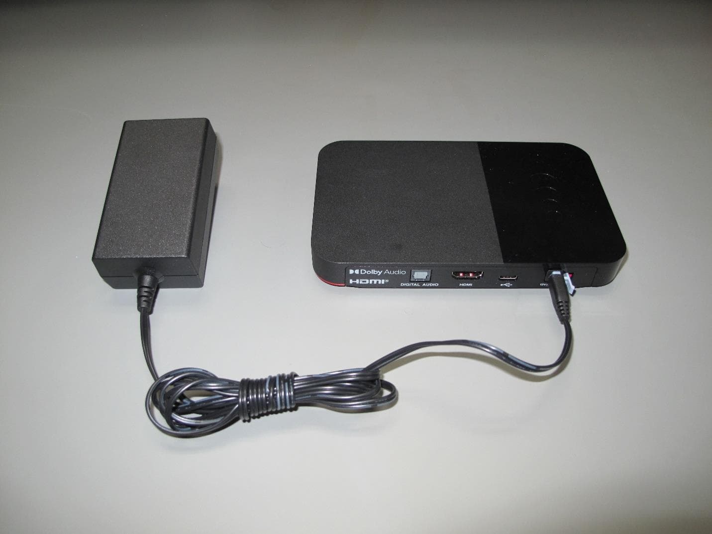
DKNHRT4
Feb 27, 2023WHOLE HOME DVR ACCESSORY
Equipment Class
DSS - Part 15 Spread Spectrum Transmitter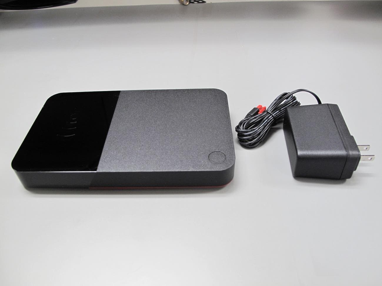
DKNQ65V
Jan 10, 2023TV SET TOP BOX
Equipment Class
NII - Unlicensed National Information Infrastructure TX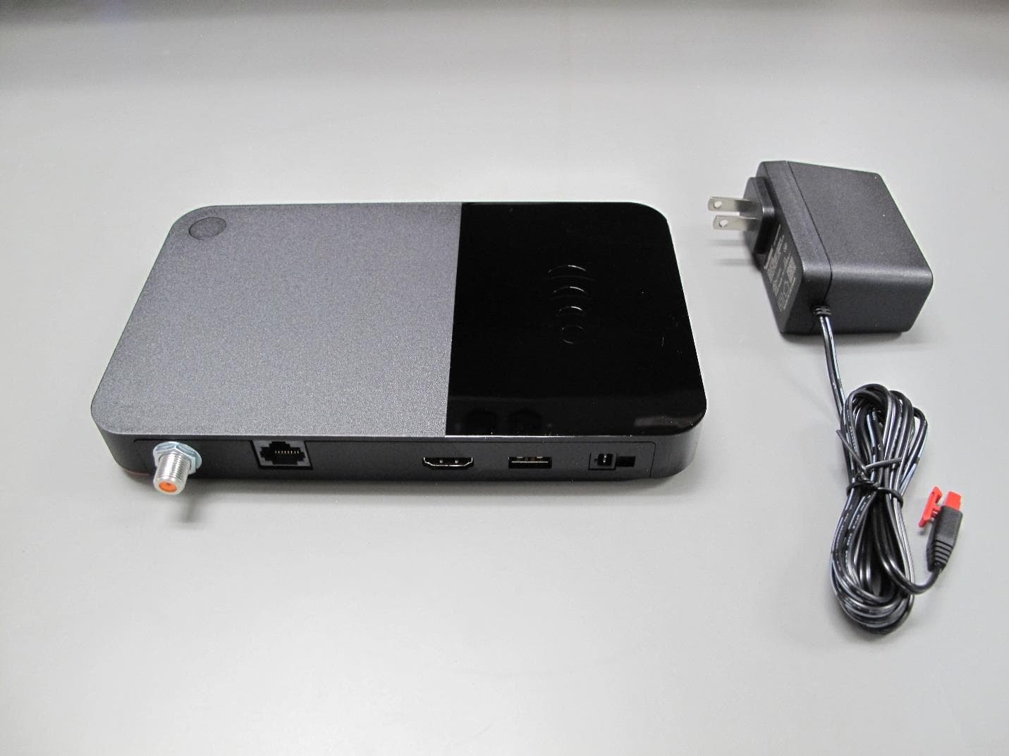
DKNP27TJ
Nov 08, 2022TV SET TOP BOX CLIENT
Equipment Class
DTS - Digital Transmission System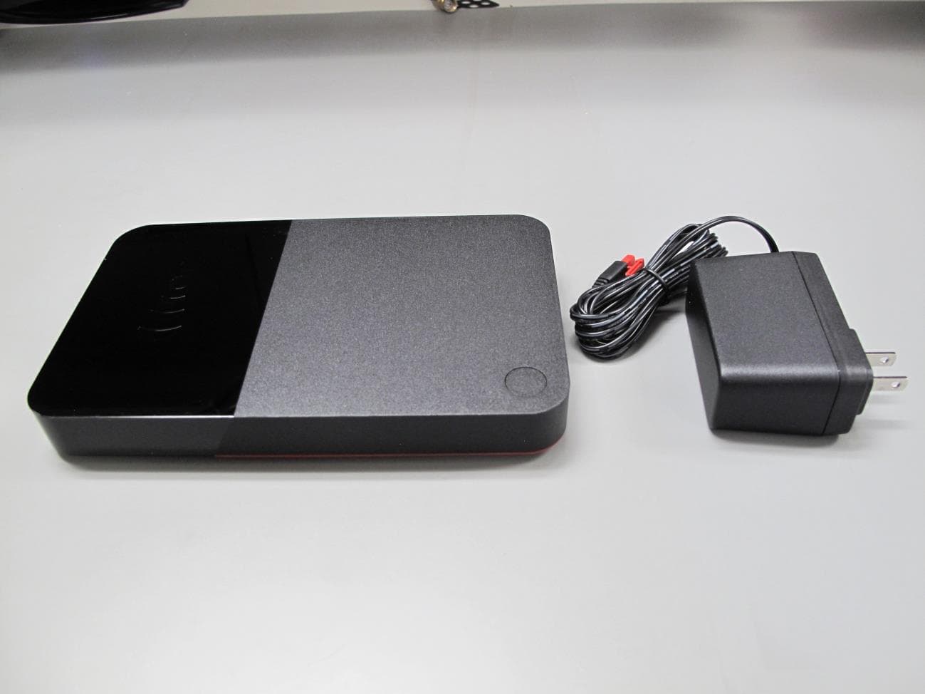
DKNHR44
Apr 13, 2022TV SET TOP BOX
Equipment Class
DSS - Part 15 Spread Spectrum Transmitter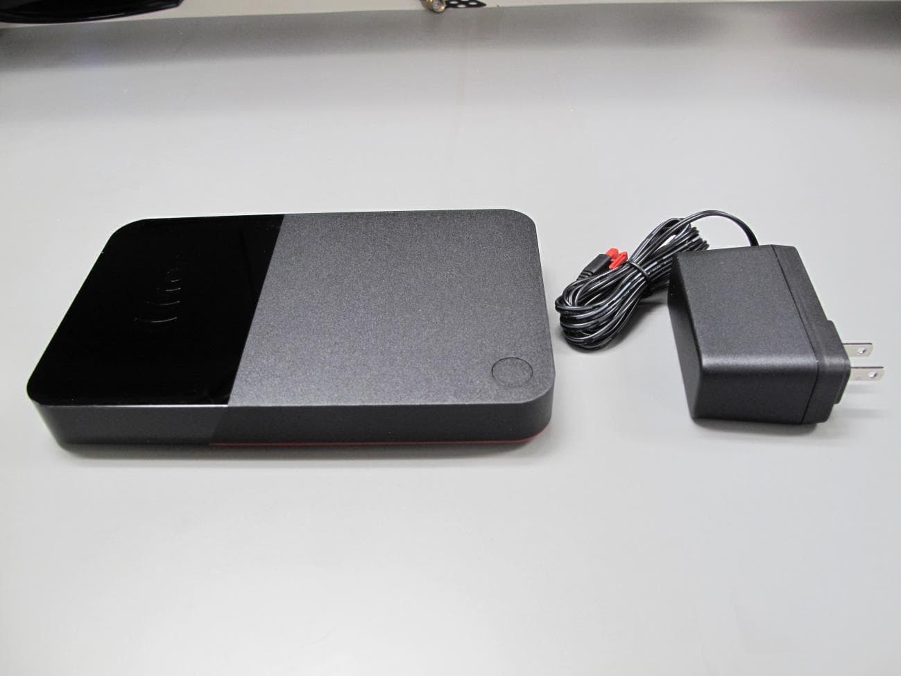
DKNRW33
Jun 09, 2021TV SET TOP BOX
Equipment Class
DTS - Digital Transmission System