DKNFSK64RReplacement Remote for Satellite Receiver
DISH Technologies L.L.C.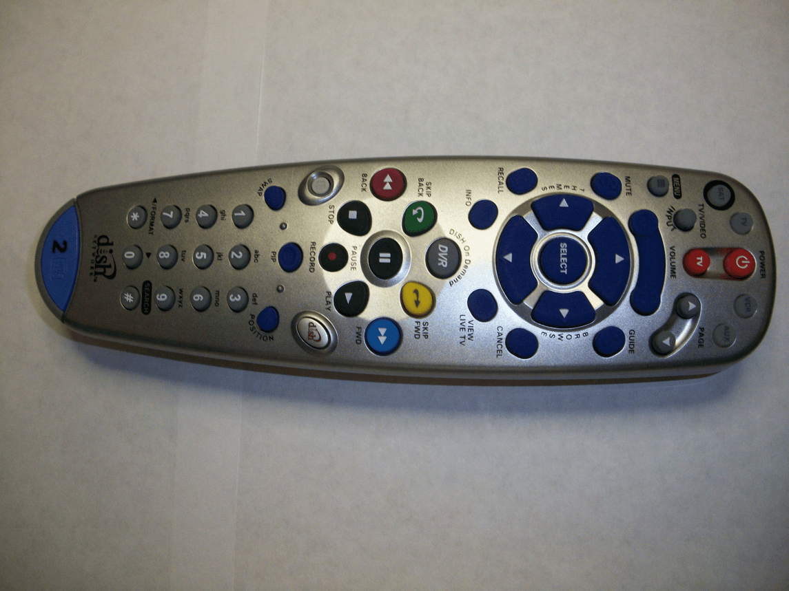
Click to zoom
Application Details
- Equipment Class
- DSC - Part 15 Security/Remote Control Transmitter
- Date of Grant
- Oct 20, 2010
- Application Purpose
- Original Equipment
- Date of Application
- Sep 29, 2010
- Equipment Note
- Replacement Remote for Satellite Receiver
- Frequency Range
- 369.50000000 - 394.37500000
- Company
- DISH Technologies L.L.C.
- Country
- United States
Documents & Files
Document Text
Text extracted from the exhibit documents filed with the FCC. Open a document above to read the original.
Users Manual
6.4 REMOTE CONTROL USER GUIDE dish Table of Contents Quick Setup Confirm Your Receiver Model ...............................................S-1 Install Your Selected Key .......................................................S-2 Insert the Batteries.................................................................S-2 Making the Remote Work with Your Receiver .......................S-3 Program the Remote to Control Your TV ...............................S-4 Programming the Recover Button for TV2 Operation ............S-5 Placing Your Remote in Limited Mode...................................S-6 Operation If You Lose Your Picture ........................................................S-6 SAT Mode ..............................................................................S-7 TV Mode ................................................................................S-8 VCR Mode .............................................................................S-9 Remote Control Overview......................................................... 1 Using the Guide ........................................................................ 1 Remote Control Modes ............................................................. 1 How the Remote Communicates .............................................. 2 Programming for Other Equipment ........................................... 2 Combination Equipment (for example, TV/VCR) ...................... 2 Limited Mode ............................................................................ 3 Fixed Channel Mode................................................................. 3 Setting (or Changing) Fixed Channel Mode for TV/VCR .......... 3 Removing Fixed Channel Mode for TV/VCR ............................ 3 Programming Using Equipment Code Tables ........................... 4 Scanning for Equipment Codes ................................................ 6 Switching Between TV and Amplifier Volume Control ................................................................................ 7 Programming the Remote to Control a Second Receiver in AUX Mode ...................................................................... 8 Reading Out the Remote Control Codes .................................. 9 Discrete Codes for Learning Remotes.....................................11 Avoiding Remote Conflicts...................................................... 12 Changing the Remote and Receiver Address ........................ 12 Changing the UHF Frequency Using the A/B Switch— DISH Player-DVR 942, Duo ViP ® 222, DuoDVR™ ViP ® 622 DVR, and DuoDVR™ ViP ® 722 DVR Only ...................................... 13 Setting Up a TV1 UHF Pro Remote for the DuoDVR™ 522 and DuoDVR™ 625 Only ....................... 14 Equipment Codes ................................................................... 16 Troubleshooting ...................................................................... 24 Regulatory Factors ................................................................. 26 Your Remote Control Codes .......................... Inside Back Cover REMOTE CONTROL USER GUIDE Use the key that looks like this Use the key that looks like this 1 If your receiver looks like one of these... If your receiver looks like one of these... If your receiver looks like one of these... If your receiver looks like one of these... If your receiver looks like this... Use the key that looks like this DISH 501 & DISH 508 / DISH Player-DVR 510 DISH 6000 DISH 721 DuoDVR™ 522 DuoDVR™ 625 Use the key that looks like this S-1 Solo ViP ® 211k DISH 411 & Solo ViP ® 211 then Select the Right Key Remote keys are included in this replacement remote kit. Quick Setup Keys have two sides. Look on both sides to find the right key for your remote. OR IR UHF Pro OR IR UHF Pro Solo DVR ViP ® 612 Use the key that looks like this Confirm Your Receiver Model Duo ViP ® 222 & DuoDVR™ ViP ® 622 DuoDVR™ ViP ® 722 DISH JVC IRR The remote functions as needed in regards to watching your satellite television and VCR. It does not rewind or fast forward while watching a recorded VCR tape. A B 1 S-2 A B BatteryBattery 1 A B Battery Battery Separate the key from the remote by inserting your thumbnail or a coin in the crease. Remove the key by grasping at the bottom. Insert face up the key you selected on the previous page. Pull the remote battery cover off. Note: If you are using the blue TV2 key that comes already installed in your remote, skip this step and proceed with the next step (Insert the Batteries). Install Your Selected Key 2 Insert the Batteries 3 12 1 Replace the remote battery cover. Insert 4 AAA batteries, making sure to match the plus (+) ends with the plus markings on the battery case. 2 Quick Setup 3 S-3 Quick Setup RECORD Turn your receiver and TV on, and press SYSTEM INFO on the front of the receiver. Confirm that you see the System Information screen. Press RECORD on your remote. The remote address probably changes on the screen. Using your remote, select Done on the System Info screen to confirm that your remote operates your receiver. If your remote has a blue number 2 key, you may need to go to your remote TV2 location to confirm your remote operates your receiver. If this is not working, go back to step 5. Making the Remote Work With Your Receiver 4 3 2 1 5 6 4 R E M OT E A N TE N N A If you installed a UHF key, make sure the UHF antenna is installed on the back of the receiver. Green (not black) UHF Pro Symbol If you installed one of these keys, continue with step2on this page. If you installed this key, go to page14 inside this guide. S-4 Quick Setup Turn your TV on. Press & hold the TV Mode button until all Mode buttons light up. Press POWER. Press the UP ARROW on the remote repeatedly (about 1 press per second) until your TV turns off. Press POUND. The TV Mode button flashes three times. Press the POWER button to turn the TV on and try other buttons to make sure the code works. If you want to try another code, star…
Text truncated - open the document above for the full version.
Cover Letter(s)
TECHNOLOGIES L.L.C. EchoStar Technologies L.L.C. 90 Inverness Circle East Englewood, CO 80112 (303) 706-5467 September 29, 2010 Federal Communications Commission 7435 Oakland Mills Road Columbia, MD 21046 To Whom It May Concern: I hereby appoint Ian Schroeder to sign letters and applications for any filings with regulatory agencies on our behalf, and to receive and exchange data between our company, the agents company and the agency in connection with certification for any products that our company owns or manufactures. Sincerely, Charles Grasso Regulatory Compliance Engineer EchoStar Technologies L.L.C. 90 Inverness Cir E Englewood, CO 80112 303-706-5467
Cover Letter(s)
TECHNOLOGIES L.L.C. EchoStar Technologies L.L.C. 90 Inverness Circle East Englewood, CO 80112 (303) 706-5234 August 23, 2010 Federal Communications Commission 7435 Oakland Mills Road Columbia, MD 21046 RE: DKNFSK64R To Whom It May Concern: This letter is to comply with Sections 0.459 and 0.457(d)(2)(i) pertaining to confidential material. Echostar Technologies L.L.C. would like the following documents regarding this submission be kept confidential. • Operational Description • Block Diagram • Schematics • Part List • Antenna Specifications The above material contains trade secrets or technical data, which would customarily be guarded from competitors. We do not want these documents to be accessible to the general public. Sincerely, Ian Schroeder Regulatory Compliance Engineer
Cover Letter(s)
TECHNOLOGIES L.L.C. EchoStar Technologies L.L.C. 90 Inverness Circle East Englewood, CO 80112 (303) 706-5234 August 23, 2010 To Whom It May Concern: We the undersigned, hereby authorize CKC Laboratories, Inc., to act on our behalf in all manners relating to application for equipment authorization, including signing of all documents relating to these matters. Any and all acts carried out by CKC Laboratories, Inc., on our behalf shall have the same affect as acts of our own. This authorization is valid until further written notice from EchoStar Technologies L.LC. Sincerely Ian Schroeder Regulatory Compliance Engineer
ID Label/Location Info
This rendering is for reference only. It is not to scale and design features may vary upon engineering review. This is Proprietary Information of Universal Electronics Inc. CONCEPTUAL CONFIDENTIAL Style.Rev. Dish Retail 6.4 X.Y.Z. Dimensions Cesar Alvarado 08 09 10 Scale 1:1 milimeters Colin Altena PM. ID. 1 C 200.0 x 57.0 x 30.0 2010 Electrical Design Industrial Design 2065 Universal Electronics Inc. FCC ID: DKNFSK64R
Operational Description
FSK/OOK 5 Channel Transmitter Theory of Operation The purpose of the FSK/OOK transmitter PWA is to allow for a multi-channel and dual modulation mode of operation. The five channel low power FSK/OOK transmitter operates with an FSK deviation of +/- 35 KHz typical. The unit can transmit at the following FSK modulated frequencies (one at a time): 369.5 MHz 375.3 MHz 388.3 MHz 394.3 Mhz In addition, the transmitter operates with OOK modulation at 384 MHz in order to support the “legacy” mode of operation. The modulation depth is in excess of 60 dB. None of the FSK transmit modes are active in this mode. A single reference oscillator crystal of 9.8304 MHz is employed in the circuit. The custom RFIC VCO/PPL circuit multiplies up the reference frequency to produce the correct RF output frequency. The operating mode and frequency is determined by the state of four input I/O lines. A static “low” or “high” signal is applied to each of the lines in different combinations (in truth table fashion) for each mode and frequency of operation. The operating voltage of the circuit is 3.0 volts, which is provided by an enabled voltage regulator. The input voltage of the regulator is the series combination of (4) AAA batteries. The control signals to the RFIC are nominally 3 volts and generated by the remote control main board microcontroller. RF output power level in FSK and OOK modes is set independently by “power set” resistors in series with ground. FSK Mode: A button press causes the transmitter to be sequenced ON such that the VCO is locked on channel before it starts transmitting. After 5 milliseconds the first ” key code” is sent, followed by additional packets if the key is held down. OOK Mode: A button press causes the transmitter to be sequenced ON such that the VCO stays ON as long as button press is detected. The OOK is achieved by toggling the “ PA Enable” pin of the RFIC high/low. In-between button presses, the transmitter circuit is completely powered down by disabling the voltage regulator. The circuit is also completely powered down in-between packets when in FSK mode. There is an impedance matching circuit followed by a multistage low pass filter at the power amp pin of the RFIC to minimize harmonic and spurious output of the transmitter. The antenna is a fractional wavelength monopole bent over the shape of a “ paperclip” . The antenna is not terminated, and a shunt inductor is used at the antenna connection to simulate its inductance when terminated in a short, which allows for a “ shorted termination” in the model, but also increased power output from the antenna itself.
Test Report
This report is for the exclusive use of Intertek's Client and is provided pursuant to the agreement between Intertek and its Client. Intertek's responsibility and liability are limited to the terms and conditions of the agreement. Intertek assumes no liability to any party, other than to the Client in accordance with the agreement, for any loss, expense or damage occasioned by the use of this report. Only the Client is authorized to permit copying or distribution of this report and then only in its entirety. Any use of the Intertek name or one of its marks for the sale or advertisement of the tested material, product or service must first be approved in writing by Intertek. The observations and test results in this report are relevant only to the sample tested. This report by itself does not imply that the material, product, or service is or has ever been under an Intertek certification program. EMC Report for EchoStar Technologies, LLC on the 6.4 IR UHF Pro Remote Page 1 of 61 TEST REPORT Report Number: 100189018DEN-001 Project Number: 100189018 Report Issue Date: 08/31/2010 Product Designation: 6.4 IR UHF Pro Remote Standards: FCC CFR47 Part 15.231 RSS-210, Issue 7: 2007 IC RSS-Gen, Issue 2: 2007 (In-Part) Tested by: Client: Intertek Testing Services NA, Inc. 1795 Dogwood Street, Suite 200 Louisville, CO 80027 Emissions Testing Facility 40 Meadow Rd Pinewood Springs, CO 80540 Echostar Corporation dba EchoStar Technologies, LLC 94 Inverness Terrace East Englewood, CO 80112 Report Prepared by: Randy Thompson Report reviewed by: EMC Senior Project Engineer Intertek Report Number: 100189018DEN-001 Issued: 08/31/2010 EMC Report for EchoStar Technologies, LLC on the 6.4 IR UHF Pro Remote Page 2 of 61 TABLE OF CONTENTS 1 Introduction and Conclusion .............................................................................................................. 3 2 Test Summary ...................................................................................................................................... 3 3 Description of Equipment Under Test................................................................................................ 4 4 System setup including cable interconnection details, support equipment and simplified block diagram ........................................................................................................................................................ 5 5 Radiated Emissions – Unintentional & Spurious.............................................................................. 7 6 AC Mains Conducted Emissions – Test not Applicable................................................................. 18 7 Radiated Emissions – Manual On/Off Timing.................................................................................. 19 8 Radiated Intentional Emissions – Fundamental & Harmonics of Fundamental .......................... 26 9 Radiated Emissions – 20dBc Emission Bandwidth........................................................................ 37 10 Radiated Emissions – Occupied Bandwidth................................................................................ 44 11 Duty Cycle Correction Factor – Justification............................................................................... 55 12 Measurement Uncertainty.............................................................................................................. 60 13 Revision History ............................................................................................................................. 61 Intertek Report Number: 100189018DEN-001 Issued: 08/31/2010 EMC Report for EchoStar Technologies, LLC on the 6.4 IR UHF Pro Remote Page 3 of 61 1 Introduction and Conclusion The tests indicated in section 2.0 were performed on the product constructed as described in section 3.0. The remaining test sections are the verbatim text from the actual data sheets used during the investigation. These test sections include the test name, the specified test Method, a list of the actual Test Equipment Used, documentation Photos, Results and raw Data. No additions, deviations, or exclusions have been made from the standard(s) unless specifically noted. Based on the results of our investigation, we have concluded the product tested complies with the requirements of the standard(s) indicated. The results obtained in this test report pertain only to the item(s) tested. 2 Test Summary Section Test full name Test date Result 5 Radiated Emissions – FCC CFR 47 Part 15B,Class B (15.209) / 15.231(b)(3) 08/10/10 Pass 6 AC Mains Conducted Emissions – FCC CFR 47 15.107, Class B ----- N/A 7 Radiated Emissions – Manual On/Off Timing per FCC 15.231(a)(1) (Complies with RSS-210, A1.1.1 08/11/10 Pass 8 Radiated Intentional Emissions – Fundamental & Harmonics of Fundamental (Spurious) per FCC (15.205) / 15.231(b)(1)(2)(3) (Complies with RSS-210, A1.1.2 (1)(2)(3) 08/10/10 Pass 9 Radiated Emissions – 20dBc Emission Bandwidth - FCC 15.231(c) (Complies with RSS-210, A1.1.3 08/11/10 Pass 10 Radiated Emissions – Occupied Bandwidth - RSS-Gen, Section 4.6.1 08/11/10 Pass Notes: The following remarks are to be considered as “where applicable“ and should be taken into account while completing any FCC/IC/ETSI radio tests at Intertek-Louisville Lab. 1) Product is battery-powered – Conducted Emissions not applicable. 2) Testing was performed in 3 different orthogonal axes to determine the worst case emissions from the device. The worst case emissions measurements are shown in this report. 3) FCC CFR47 Part 15.31: Measurement Standards: In any case where the device is powered off a battery, a fresh battery was used during test. In cases where the device is powered off an AC supply, voltage was varied per Part 15.31 to find worst case emissions. 4) FCC CFR47 Part 15.35: Measurement Detector Functions and Bandwidths were utilized when performing the measurements within this report. Measurements were taken utilizing the m…
Text truncated - open the document above for the full version.
Test Report
Supplemental information for Intertek Report 100189018DEN-001 regarding page 7 spurious emissions <30MHz: Ian, Please find antenna information below. Asset ID: 18897 Description: Magnetic (Active Loop) Antenna (10kHz to 30MHz) Manufacturer: EMCO Model: 6502 Serial #: 9205-2738 Date of Cal: 10/28/2009 Cal Due Date: 10/28/2010 Let me know if you need anything else. Regards, Randy T Randall Thompson EMC Senior Project Engineer Phone 303-786-7999 Intertek 1795 Dogwood Street, Suite 200 Louisville, CO 80027 Fax: 303-449-6160 Cell: 970-689-7685 E-Mail: [email protected] http://www.intertek-etlsemko.com/
Contact Information
Applicant
Ian Schroeder(Senior Engineer)
Technical Contact
EchoStar Technologies, LLCIan Schroeder
[email protected]303-706-5234
90 Iverness Cir. E · Englewood, Colorado · United States
Non-Technical Contact
EchoStar Technologies, LLCRobert Wallen
Test Firm
Intertek Testing Services NA, Inc.Jay Kogoma
Technical Specifications
| # | Rule Parts | Frequency Range | Power Output |
|---|---|---|---|
| 1 | 15.231 | 369.5 MHz - 394.375 MHz | - |
Other Applications from DISH Technologies L.L.C.
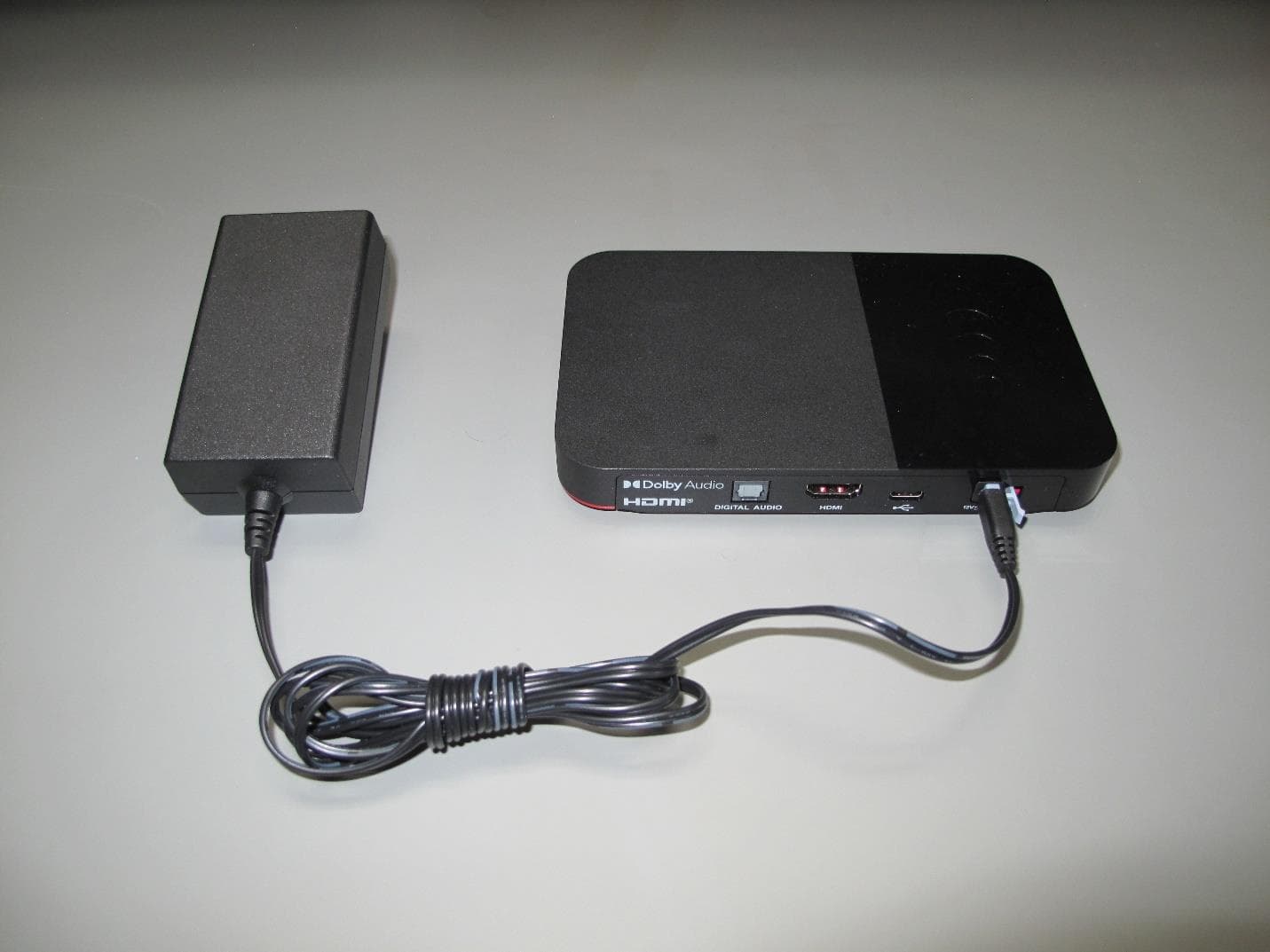
DKNHRT4
Feb 27, 2023WHOLE HOME DVR ACCESSORY
Equipment Class
DSS - Part 15 Spread Spectrum Transmitter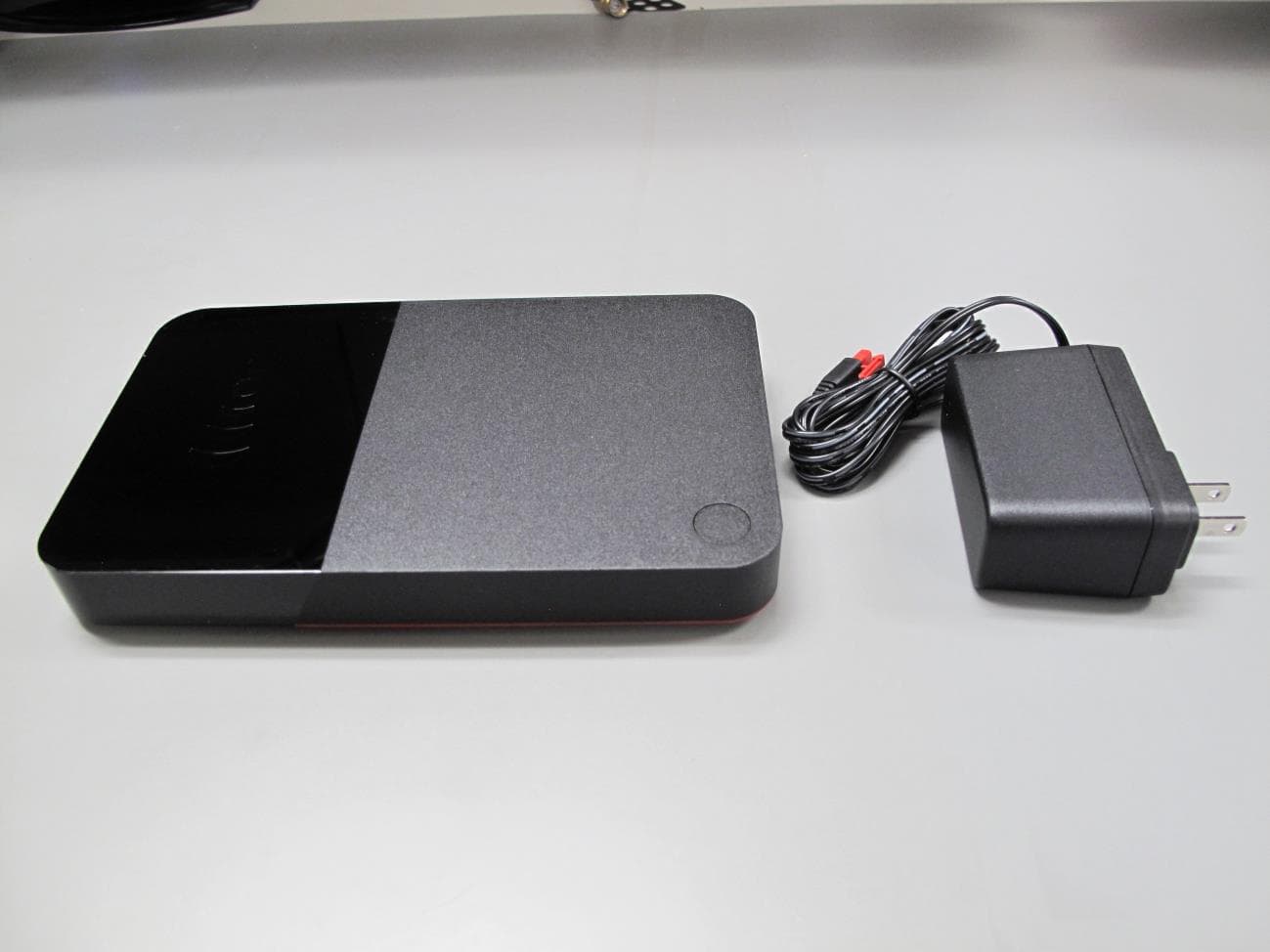
DKNQ65V
Jan 10, 2023TV SET TOP BOX
Equipment Class
NII - Unlicensed National Information Infrastructure TX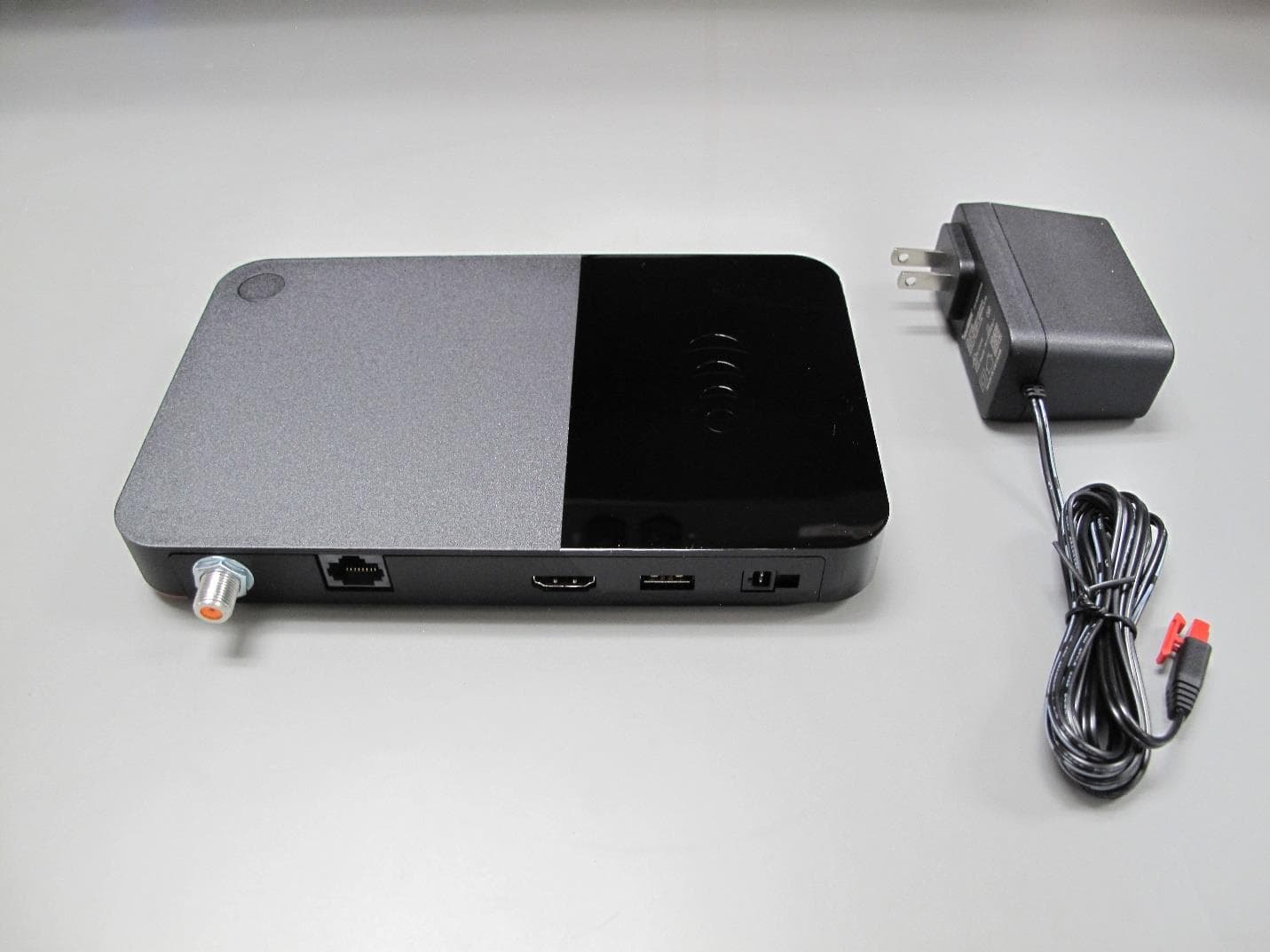
DKNP27TJ
Nov 08, 2022TV SET TOP BOX CLIENT
Equipment Class
DTS - Digital Transmission System
DKNHR44
Apr 13, 2022TV SET TOP BOX
Equipment Class
DSS - Part 15 Spread Spectrum Transmitter
DKNRW33
Jun 09, 2021TV SET TOP BOX
Equipment Class
DTS - Digital Transmission System