DKNYT1300MoCa Converter Set Top Box
DISH Technologies L.L.C.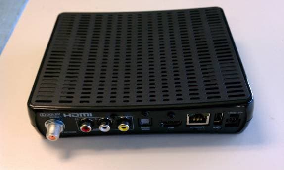
Click to zoom
Application Details
- Equipment Class
- DTS - Digital Transmission System
- Date of Grant
- Jul 28, 2011
- Application Purpose
- Original Equipment
- Date of Application
- Jul 28, 2011
- Equipment Note
- MoCa Converter Set Top Box
- Frequency Range
- 2425.00000000 - 2475.00000000
- Company
- DISH Technologies L.L.C.
- Country
- United States
Documents & Files
Document Text
Text extracted from the exhibit documents filed with the FCC. Open a document above to read the original.
Users Manual
XiP110 User Guide Warning and Attention Symbols You must be aware of safety when you install and use this system. This User Guide provides various procedures. If you do some of these procedures carelessly, you could injure or kill yourself or damage equipment or property. Some other procedures require special attention. The lightning flash with arrowhead symbol, within an equilateral triangle, is intended to alert the user to the presence of uninsulated “dangerous voltage” within the product’s enclosure that may be of sufficient magnitude to constitute a risk of electric shock to persons. The exclamation point within an equilateral triangle is intended to alert the user to the presence of important operating and maintenance (servicing) instructions in the literature accompanying the appliance. The Class II equipment symbol means the equipment has additional insulation and does not need to be grounded. For Your Safety Warning: Do not try to open the case of the XiP110. There is risk of electrical shock, which may cause damage to the XiP110 and/or personal injury or death to you. There are no user-serviceable parts inside the XiP110. Opening the XiP110 case or making unauthorized changes will void the warranty. Warning: To reduce the risk of fire or electric shock, do not expose this appliance to rain or moisture. Important Software Notice As with all software controlled products, unexpected behavior could arise if the user tries to perform operations in a non-routine manner. This product, like almost any other high tech product, is subject to bugs and hence EchoStar CANNOT AND DOES NOT GUARANTEE OR WARRANT THAT ALL FEATURES, SUCH AS PARENTAL CONTROL, WILL WORK AS INTENDED UNDER ALL CIRCUMSTANCES. EchoStar endeavors to improve such conditions and will periodically download improvements. Equipment and Software Covered by this User Guide This User Guide covers the XiP110 and software models XiP110. This User Guide may cover other devices not listed here. i Publishing Information Copyright © 2011. EchoStar Technologies L.L.C., Englewood, Colorado 80112. All rights reserved. The information in this User Guide may change without notice. Revisions may be issued to tell you about such changes. Send comments or questions about this User Guide to [email protected] or Technical Publications, EchoStar Technologies L.L.C, 90 Inverness Drive Circle East, Englewood, Colorado 80112. Document Number: 188869 Printed in DISH Network is a registered trademark of DISH Network L.L.C. All product names, trade names, or corporate names mentioned in this User Guide are acknowledged to be the proprietary property of the registered owners. Manufactured under license from Dolby Laboratories. “Dolby” and the double-D symbol are trademarks of Dolby Laboratories. HDMI, the HDMI logo and High-Definition Multimedia Interface are trademarks or registered trademarks of HDMI Licensing LLC. This equipment may incorporate copyright protection technology that is protected by U.S. patents, patent applications, and/or other intellectual property rights. Use of such copyright protection technology is intended for home and other limited pay-per-view uses only unless otherwise authorized. Reverse engineering or disassembly is prohibited. ii 1 Read these instructions. 2 Keep these instructions. 3 Heed all warnings. 4 Follow all instructions. 5 Do not use the apparatus near water. 6 Clean only with a dry cloth. 7 Do not block any ventilation openings. Install in accordance with the manufacturer’s instructions. 8 Use only with the cart, stand tripod, bracket, or table specified by the manufacturer, or sold with the apparatus. When a cart is used, use caution when moving the cart/ apparatus combination to avoid injury from tip-over. 9 Do not install near any heat sources such as radiators, heat registers, stoves, or other apparatus (including amplifiers) that produce heat. 10 Do not defeat the safety purpose of the polarized or grounding-type plug. A polarized plug has two blades with one wider than the other. A grounding-type plug has two blades and a third grounding prong. The wide blade or the third prong are provided for your safety. If the provided plug does not fit into your outlet, consult an electrician for replacement of the obsolete outlet. 11 Protect the power cord from being walked on or pinched, particularly at plugs, convenience receptacles, and the point where they exit from the apparatus. 12 Only use attachments/accessories specified by the manufacturer. 13 Unplug the apparatus during lightning storms or when unused for long periods of time. 14 Refer all servicing to qualified service personnel. Servicing is required when the apparatus has been damaged in any way, such as the power supply cord or plug is damaged, liquid has been spilled or objects have fallen into it, the apparatus has been exposed to rain or moisture, does not operate normally, or has been dropped. 15 The power plug must be readily accessible so that the apparatus can be easily disconnected from the AC power. 16 The XiP110 is still connected to the AC power whenever it is plugged into a live power outlet, even if it is turned off using the remote control or front panel buttons. 17 No flame sources, such as lit candles, should be placed on the equipment. 18 The apparatus shall not be exposed to dripping or splashing, and no objects filled with liquids, such as vases, shall be placed on the top of it. 19 Operate the XiP110 using only the type of power source indicated on the marking label. Unplug the XiP110 power cord by gripping the power plug, not the cord. Important Safety Instructions iii Important Safety Information, continued 20 Do not overload wall outlets or extension cords; this can result in a risk of fire or electrical shock. 21 Never insert objects of any kind into the XiP110 through openings, as the objects may touch dangerous voltage points or short out parts. This could cause fire or electrical shock. 22 Do not locate the antenna near …
Text truncated - open the document above for the full version.
Cover Letter(s)
TECHNOLOGIES L.L.C. EchoStar Technologies L.L.C. 90 Inverness Circle East Englewood, CO 80112 (303) 706-5234 July 14, 2011 Federal Communications Commission 7435 Oakland Mills Road Columbia, MD 21046 RE: DKNYT1300 To Whom It May Concern: This letter is to comply with Sections 0.459 and 0.457(d)(2)(i) pertaining to confidential material. Echostar Technologies L.L.C. would like the following documents regarding this submission be kept confidential. • Operational Description • Block Diagram • Schematics • Part List The above material contains trade secrets or technical data, which would customarily be guarded from competitors. We do not want these documents to be accessible to the general public. Sincerely, Ian Schroeder Regulatory Compliance Engineer
Cover Letter(s)
TECHNOLOGIES L.L.C. EchoStar Technologies L.L.C. 90 Inverness Circle East Englewood, CO 80112 (303) 706-5234 December 1, 2010 To Whom It May Concern: We the undersigned, hereby authorize CKC Laboratories, Inc., to act on our behalf in all manners relating to application for equipment authorization, including signing of all documents relating to these matters. Any and all acts carried out by CKC Laboratories, Inc., on our behalf shall have the same affect as acts of our own. This authorization is valid until further written notice from EchoStar Technologies L.LC. Sincerely Ian Schroeder Regulatory Compliance Engineer
Cover Letter(s)
TECHNOLOGIES L.L.C. EchoStar Technologies L.L.C. 90 Inverness Circle East Englewood, CO 80112 (303) 706-5467 September 29, 2010 Federal Communications Commission 7435 Oakland Mills Road Columbia, MD 21046 To Whom It May Concern: I hereby appoint Ian Schroeder to sign letters and applications for any filings with regulatory agencies on our behalf, and to receive and exchange data between our company, the agents company and the agency in connection with certification for any products that our company owns or manufactures. Sincerely, Charles Grasso Regulatory Compliance Engineer EchoStar Technologies L.L.C. 90 Inverness Cir E Englewood, CO 80112 303-706-5467
ID Label/Location Info
This device complies with part 15 of the FCC Rules. Operation is subject to the following two conditions: (1) this device may not cause harmful interference, and (2) this device must accept any interference received, including interference that may cause undesired operation. Manufactured under license from Dolby Laboratories. “Dolby” and the double-D symbol are trademarks of Dolby Laboratories. TITLE SCALE 1:1 SIZE DWG. NO A SHEET 1 of 1 REV 01 APPROVALSDATE UNLESS OTHERWISE SPECIFIED DIMENSIONS ARE IN MM. DRAWN CHECKED REVISIONS ECOITEM MASTER DESCRIPTION REVDATEBY TOLERANCES: 0.000 +/- .125 0.00 +/- .25 0.0 +/- .4 0. +/- .7 HOLE DIA: +/- .075 ANGLES: +/- .5 C31778187007INITIAL RELEASE @ DEVELOPMENT 01 05/27/11JW JASON WALKER05/27/11 187007 LABEL, PRODUCT ID, XIP110 NOTES: 1. ALL DIMENSIONS ARE IN MILLIMETERS, UNLESS OTHERWISE NOTED. 2. PLACE ARTWORK ONTO LABEL AS SHOWN. 3. MATERIAL: 3M 7815 (Thermal Transfer Polyester Label) OR ECHOSTAR-APPROVED EQUIVALENT Facestock: 2.3 mil Polyester Adhesive: 1.1 mil #310 Acrylic Liner: 3.2 mil #55 Densified Kraft ALT. MATERIAL: AVERY BW9664 Facestock: Polypropylene Adhesive: Acrylic based and permanent Liner: Super-calendered white glassine paper -THE LABEL/RIBBON COMBINATION MUST HAVE UL PGJI2 AND EITHER UL PGJI8 OR EQUIVALENT CSA RECOGNITION, WITH A RATING OF 80ºC MINIMUM AND SUITABLE FOR APPLICATION TO GALVANIZED STEEL, ABS AND PC. 4. PRINT COLOR: ALL GRAPHICS AND TEXT TO BE COOL GREY 2C OR ECHOSTAR-APPROVED EQUIVALENT BACKGROUND COLOR: PANTONE STANDARD BLACK 5. LABELS MUST BE PRINTED ON ROLLS. 6. PRINT SERIAL NUMBERS HERE, REFER TO 188526 FOR UNIT AND PWA SERIAL NUMBER FORMAT. 7. QUALITY ASSURANCE PROVISIONS: IN ADDITION TO MEETING ALL REQUIREMENTS OUTLINED IN THIS SPECIFICATION, ALL REQUIREMENTS IN THE FOLLOWING ECHOSTAR QUALITY ASSURANCE DOCUMENTS AND THEIR REFERENCES MUST BE MET OR EXCEEDED. A) 124214 SUPPLIER AQL REQUIREMENTS B) 105450 SUPPLIER QA REQUIREMENTS C) 123473765-AA COSMETIC PROVISIONS Scale: 100% Use this image for reference 90.00 53.00 Scale: 100% Use this image to create Artwork (Pantone Cool Grey 2C only) 6 This device complies with part 15 of the FCC Rules. Operation is subject to the following two conditions: (1) this device may not cause harmful interference, and (2) this device must accept any interference received, including interference that may cause undesired operation. Manufactured under license from Dolby Laboratories. “Dolby” and the double-D symbol are trademarks of Dolby Laboratories.
Parts List/Tune Up Info
TECHNOLOGIES L.L.C. EchoStar Technologies L.L.C. 90 Inverness Circle East Englewood, CO 80112 (303) 706-5234 July 14, 2011 Federal Communications Commission 7435 Oakland Mills Road Columbia, MD 21046 RE: DKNYT1300 To Whom It May Concern: This letter covers the tune up procedure details. The transmitter circuit used in this product has *no* tune up features. The circuit will function at its desired power and frequency upon assembly. Sincerely, Ian Schroeder Regulatory Compliance Engineer
RF Exposure Info
2.1091 Radiofrequency radiation exposure evaluation: mobile devices In accordance with KDB 447498, our product is exempt from making such studies or preparing MPE due to our product’s power output being below the lower threshold requiring RF exposure evaluation.
Test Report
EMC Report for EchoStar Technologies, LLC on the Model: DE51 Page 1 of 109 TEST REPORT Report Number: 100457286DEN-002 Project Number: G100457286 Report Issue Date: 7/25/2011 Product Designation: Model DE51 Standards: FCC 47 CFR Part 15.247 IC RSS 210: Issue 8:2010 IC RSS-GEN Issue 3:2010 Tested by: Client: Intertek Testing Services NA, Inc. 1795 Dogwood St. Suite 200 Louisville, CO 80027 Echostar Corporation dba EchoStar Technologies LLC 90 Inverness Circle East Englewood, CO 80112 Report prepared by Report reviewed by Randy Thompson Senior EMC Project Engineer Mike Spataro Engineering Team Leader This report is for the exclusive use of Intertek's Client and is provided pursuant to the agreement between Intertek and its Client. Intertek's responsibility and liability are limited to the terms and conditions of the agreement. Intertek assumes no liability to any party, other than to the Client in accordance with the agreement, for any loss, expense or damage occasioned by the use of this report. Only the Client is authorized to permit copying or distribution of this report and then only in its entirety. Any use of the Intertek name or one of its marks for the sale or advertisement of the tested material, product or service must first be approved in writing by Intertek. The observations and test results in this report are relevant only to the sample tested. This report by itself does not imply that the material, product, or service is or has ever been under an Intertek certification program. Intertek Report Number: 100457286DEN-002 Issued:7/25/2011 EMC Report for EchoStar Technologies, LLC on the Model: DE51 Page 2 of 109 TABLE OF CONTENTS 1 Introduction and Conclusion .............................................................................................................. 3 2 Test Summary ...................................................................................................................................... 3 3 Description of Equipment Under Test................................................................................................ 5 4 System setup including cable interconnection details, support equipment and simplified block diagram ........................................................................................................................................................ 9 5 Radiated Emissions – Fundamental Power & Harmonics of the Fundamental ........................... 11 6 Radiated Emissions – Unintentional and Spurious of the Transmitter ........................................ 23 7 Band Edge Measurements – Unintentional and Spurious of the Transmitter.............................. 62 8 Unintentional Radiated Emissions - Receiver................................................................................. 67 9 6dB Bandwidth ................................................................................................................................... 81 10 Power Spectral Density (PSD)....................................................................................................... 85 11 Occupied Bandwidth (OBW).......................................................................................................... 90 12 AC Mains Conducted Emissions .................................................................................................. 96 13 Measurement Uncertainty............................................................................................................ 104 14 Duty Cycle Correction Factor...................................................................................................... 105 15 Revision History ........................................................................................................................... 106 Intertek Report Number: 100457286DEN-002 Issued:7/25/2011 EMC Report for EchoStar Technologies, LLC on the Model: DE51 Page 3 of 109 1 Introduction and Conclusion The tests indicated in section 2.0 were performed on the product constructed as described in section 3.0. The remaining test sections are the verbatim text from the actual data sheets used during the investigation. These test sections include the test name, the specified test Method, a list of the actual Test Equipment Used, documentation Photos, Results and raw Data. No additions, deviations, or exclusions have been made from the standard(s) unless specifically noted. Based on the results of our investigation, we have concluded the product tested complies with the requirements of the standard(s) indicated. The results obtained in this test report pertain only to the item(s) tested. 2 Test Summary Section Test full name Test date Result 5 Radiated Emissions – Field Strength of the Fundamental & Harmonics of the Fundamental – FCC 247(b)(3)(d)/15.205/209 (Covers RSS-210 A8.4(4) & A8.5) 07/15/2011 Pass 6 Radiated Emissions – Unintentional and Spurious of the Transmitter - FCC 15.209/15.247(d)/15.205 (Covers RSS-210 A8.5, & RSS-GEN 7.2.2) 07/18/2011 07/19/2011 07/21/2011 07/22/2011 Pass 7 Radiated Emissions – Unintentional and Spurious – Band Edge FCC 15.209/15.247(d)/15.205 (Covers RSS-210 A8.5, & RSS-GEN 7.2.2) 07/18/2011 07/19/2011 Pass 8 Radiated Emissions – Unintentional – Receiver FCC 5.209/15.247(d)/15.205 (Covers RSS-GEN Section 6) 07/18/2011 07/19/2011 Pass 9 6dB Bandwidth – FCC 15.247(a)(2) (Covers RSS-210 A8.2(a)) 07/19/2011 Pass 10 Power Spectral Density (PSD) – FCC 15.247(e) (Covers RSS-210 A8.2(b)) 07/19/2011 Pass 11 Occupied Bandwidth – RSS-GEN, Section 4.6.1 07/19/2011 Pass 12 AC Conducted Emissions – FCC 15.207 (Covers RSS-GEN Section 7.2.4) 07/19/2011 Pass Notes: 1) Product FCC Model DE51 is also marketed as XiP110 2.1 Test Facility Intertek Denver’s testing facilities are located at 1795 Dogwood St. Suite 200 Louisville, CO 80027. The testing facility is ISO17025:2005 accredited by A2LA, our lab code is 2506.02, our VCCI registration numbers are. R-1643, C-1752 and T-1558, our FCC designation no…
Text truncated - open the document above for the full version.
Test Setup Photos
Intertek Product Photo: Product Tested – Model: DE51 (MoCa Converter Set-Top Box) Intertek Product Test Photo: Product Back Panel Ports/Connectors Cables used during testing HDMI RF Coax Audio RCA Video RCA Ethernet USB 12 VDC Power Intertek Product Photo: AC Adapter – 12VDC Output Intertek Test Setup Photographs: Fundamental Power and Harmonics of the Fundamental Test setup – Field Strength Measurements (Front View) Test setup – Field Strength Measurements (Rear View) Intertek Photo: Test setup – Field Strength Measurements (Rear View Cables) Intertek Test Axis Photos Test Axis 1 (Product Flat on Table) Test Axis 2 (Product Vertical) Test Axis 3 (Product Vertical and Rotated 90 degrees) Axis 3 was determined to be the “worst-case” product orientation Intertek Photo: Antenna Setups – Fundamental & Harmonics of the Fundamental Active Loop Antenna (9kHz to 30MHz) BiLog Antenna (30MHz to 1000MHz) Intertek Photo: Antenna Setups Horn (1GHz – 18GHz) HF Active Antenna/Harmonic Mixer (18GHz – 26.5GHz) Intertek Setup Photographs: Tx Spurious & Unintentional Test setup – Field Strength Measurements (Front View) Test setup – Field Strength Measurements (Rear View) Intertek Photo: Antenna Setups – Tx Spurious Active Loop Antenna (9kHz to 30MHz) BiLog Antenna (30MHz to 1000MHz) Intertek Photo: Antenna Setups – Tx Spurious & Unintentional Horn (1GHz – 18GHz) HF Active Antenna/Harmonic Mixer (18GHz – 26.5GHz) Intertek Test Setup Photographs: 6dB Bandwidth/ PSD and Occupied Bandwidth Test setup – Field Strength Measurements (Front View) Intertek Photo: Test setup – Field Strength Measurements (Rear View) Intertek Test Setup Photographs: Rx Unintentional Test Setup – Radiated Emissions (Front View) Test Setup – Radiated Emissions (Rear View) Intertek Photo: Test Setup – Radiated Emissions (Rear View) Cables Left-to-Right: RF Coaxial, Composite A/V RCA, HDMI, Ethernet, USB, DC Power Intertek Photo: Test Antennas – Rx Unintentional BiLog (30MHz to 1000MHz) Ridge Guide Horn (1GHz to 18GHz) Note: Testing above 1GHz utilizes a boar site antenna mast Intertek Setup Photographs: AC Conducted Emissions Test Setup – Conducted Emissions (Front View) Photo: Test Setup – Conducted Emissions (Side View)
Contact Information
Applicant
Ian Schroeder(Senior Engineer)
Technical Contact
Echostar Technologies, L.L.C.Robert Wallen
[email protected]303-706-4511
90 Inverness Cir E · Englewood, Colorado · United States
Non-Technical Contact
Echostar Technologies L.L.C.Ian Schroeder
[email protected]303-706-5234
Test Firm
Intertek Testing Services NA, Inc.Paul Coghill
Technical Specifications
| # | Rule Parts | Frequency Range | Power Output |
|---|---|---|---|
| 1 | 15C | 2.42 GHz - 2.48 GHz | 3.69 mW |
Other Applications from DISH Technologies L.L.C.
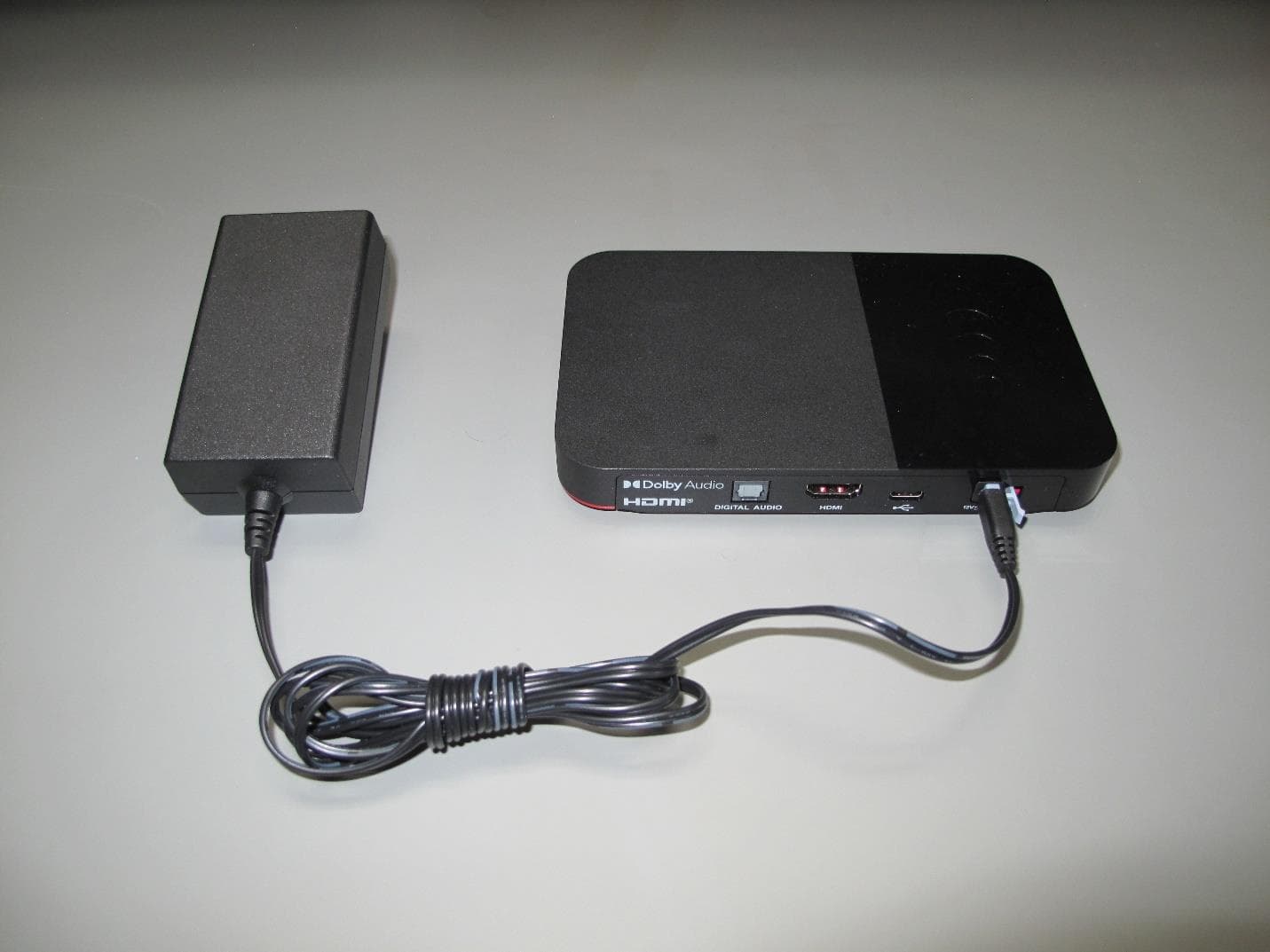
DKNHRT4
Feb 27, 2023WHOLE HOME DVR ACCESSORY
Equipment Class
DSS - Part 15 Spread Spectrum Transmitter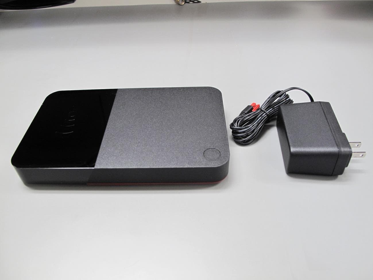
DKNQ65V
Jan 10, 2023TV SET TOP BOX
Equipment Class
NII - Unlicensed National Information Infrastructure TX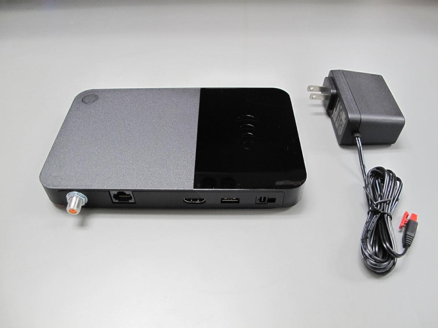
DKNP27TJ
Nov 08, 2022TV SET TOP BOX CLIENT
Equipment Class
DTS - Digital Transmission System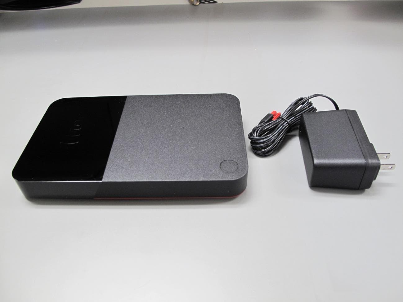
DKNHR44
Apr 13, 2022TV SET TOP BOX
Equipment Class
DSS - Part 15 Spread Spectrum Transmitter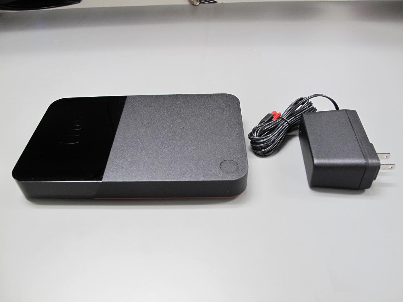
DKNRW33
Jun 09, 2021TV SET TOP BOX
Equipment Class
DTS - Digital Transmission System