DO4CP1900
Checkpoint Systems Inc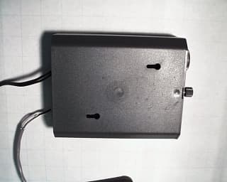
Click to zoom
Application Details
- Equipment Class
- FAP - Part 15 Anti-Pilferage Device
- Date of Grant
- Apr 06, 2000
- Application Purpose
- Original Equipment
- Date of Application
- Mar 08, 2000
- Frequency Range
- 8.43000000 - 8.66000000
- Company
- Checkpoint Systems Inc
- Country
- United States
Documents & Files
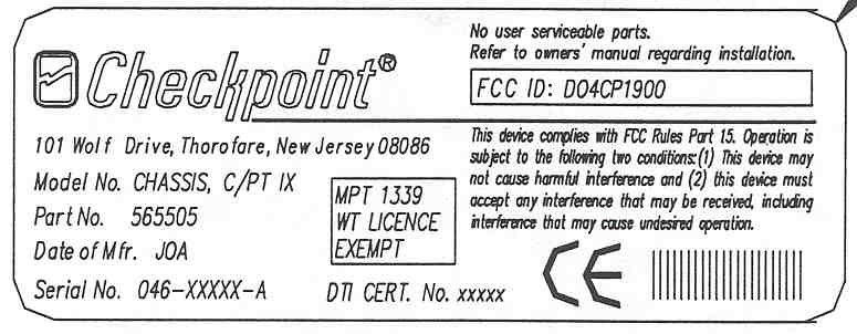
Document Text
Text extracted from the exhibit documents filed with the FCC. Open a document above to read the original.
Users Manual
476736 NOTICE TO PERSONS RECEIVING THIS DRAWING AND/OR TECHNICAL INFORM ATION: Title: INSTALLATION & TUNE-UP PROCEDURE COUNTERPOINT IX Checkp oint Sy st ems claims p rop riet ary right s t o t he mat erial disclosed hereon. This drawing and/or technical information is issued in confidence for engineering information only and may not be rep roduced or used to manufacture any thing shown or referred to hereon without direct written p ermission from Checkp oint Sy stems to the user. This drawing and/or t echnical informat ion is t he p rop ert y of Checkp oint Sy st ems and is loaned for mut ual assist ance, t o be ret urned when it s p urp ose has been served. THIS DRAWING AND/OR TECHNICAL INFORMATION IS THE PROPERTY OF CHECKPOINT S YS TEMS , INC. RevisionsRevisions RevDescriptionDateEngineerRevDescriptionDateApproved 00 Doc. Spec: Date: Dwn: Date : Chk:Date : Eng Date : Size A476736 Used On Appd : Date: Scale: N/A Checkpoint Systems, Inc. 1996Page 1 of 28 Rev. 00 TECHNICAL DOCUMENTATION INSTALLATION & TUNE-UP PROCEDURE March 9, 2000 COUNTERPOINT IX FCC ID: D04CP1900 _____________________________________________________________________________________________________________________________________________ CHECK PO IN T SYSTEMS, IN C. CO N FIDEN TIAL AN D PRO PRIETARY IN FO RMATIO N , FO R IN TERN AL USE O N LY. DWG. 476736 PAGE 2 Table Of Contents SectionDescriptionPage AForward.4 1.0System Description5-7 1.1System Overview5 1.1.1How the System Works5 1.1.2System Effectiveness 5 1.2Chassis6 1.3Powe r Supply and C/ PT re se ttable fuse6 1.4Remote Unit6 1.5Antenna6 1.6Target 6 2.0Re comme nde d Tools and Equipme nt7 2.1Electronic Test Equipment7 Table 2.1 - Recommended Electronic Test Equipment7 2.2Installation Tools7 Table 2.2 - Recommended Installation Tools7 3.0Wiring the C/PT IX8-11 3.1Powe r Conne ction8 Figure 3.1 - wire Connection8 3.2Ante nna Conne ction9 3.2.1Pad Connection9 Figure 3.2.1 - Pad Connection9 3.2.2Scanner Antenna Connection10 Figure 3.2.2 - Scanner Connection10 3.3Slaving Connection10 3.3.1Wire Slaving10 3.3.2Fiber Slaving11 3.3.3Secure Cables11 3.4Interlock Connection11 3.5Re mote Unit Conne ction11 Table 3.5 - Remote Unit Connection11 4.0Install the C/PT IX12-14 4.1Chassis Installation12 Figure 4.1A - Horizontal Chassis Installation12 Figure 4.1B - Vertical Chassis installation13 4.2Remote Unit Installation13 Figure 4.2A - Vertical Remote Unit Installation13 Figure 4.2B - Horizontal Remote Unit Installation14 Rev. 00 TECHNICAL DOCUMENTATION INSTALLATION & TUNE-UP PROCEDURE March 9, 2000 COUNTERPOINT IX FCC ID: D04CP1900 _____________________________________________________________________________________________________________________________________________ CHECK PO IN T SYSTEMS, IN C. CO N FIDEN TIAL AN D PRO PRIETARY IN FO RMATIO N , FO R IN TERN AL USE O N LY. DWG. 476736 PAGE 3 5.0C/PT IX DIP Switch Configuration14-18 5.1Ante nna Matching15 Table 5.1 - Antenna Matching Chart15 5.2IV Mode16 Table 5.2 - Settings for IV Mode16 5.3V Mode17 Table 5.3 - Settings for V Mode17 5.4VI Mode18 Table 5.4 - Settings for VI Mode18 6.0C/PT IX Tune-Up and Test Procedure19-20 6.1Center Frequency and Deviation Verification19 6.2IV Mode19 6.3V Mode19 6.4VI Mode20 6.5Interlock Turn-On Time Adjustment20 7.0After the Installation20-21 7.1Turning the Deactivator On and Off20 7.2How the Deactivator Works20 7.3When the Tag Doesn’t Deactivate20-21 7.4When the Sensing System Alarms21 7.5Testing the Deactivator21 7.6Operational Problems21 7.7Tagging21 8.0Figures and Tables22-26 8.1Test Points and Adjustments22 Figure 8.1 - Test Points and Adjustments22 8.2Slave/Inhibit Decision Chart23 Table - 8.2 C/PT IX Slaving/Inhibit Decision Chart23 8.3DIP Switch Settings24 Table 8.3 - DIP Switch Settings24 8.4INTERLOCK Time Adjustment Chart25 Table 8.4 - INTERLOCK Time Adjustment Chart25 8.5 Performance Matrix26 Table 8.5 - Performance Matrix26 Appe ndix AFine Tuning27-29 A.1 Detailed Tuning in IV Mode27-29 Figure A1.1 - AC Signal at TP2 with SW1,2 ( 1 ) On27 Figure A1.2 - AC Signal at TP2 with SW1,2 ( 5,6 ) On27 Figure A1.3 - AC Signal at TP2 with SW1,2 ( 3,4,5,6 ) On28 Figure A1.4 - AC Signal at TP429 A.2 Detailed Tuning in V Mode29 A.3 Detailed Tuning in VI Mode29 Rev. 00 TECHNICAL DOCUMENTATION INSTALLATION & TUNE-UP PROCEDURE March 9, 2000 COUNTERPOINT IX FCC ID: D04CP1900 _____________________________________________________________________________________________________________________________________________ CHECK PO IN T SYSTEMS, IN C. CO N FIDEN TIAL AN D PRO PRIETARY IN FO RMATIO N , FO R IN TERN AL USE O N LY. DWG. 476736 PAGE 4 Scope of Document This manual describes the steps necessary to install, tune, test and operate the C/PT IX Deactivation system. Manual Structure This manual is organized with the following structure: Section 1.0Describes the C/PT IX system components and how they work. Section 2.0Lists the tools recommended to install, tune and test the C/PT IX system. Section 3.0Lists and describes steps required to wire the C/PT IX system. Section 4.0Lists and describes steps required to install the C/PT IX system. Section 5.0Lists and describes steps to tune and test the C/PT IX system. Required Knowledge and Skill This manual assumes that you have the technical skill and electronic knowledge you need to: • Read a wiring diagram • Connect and read electronic test instruments • Make electrical wiring connections • Do light construction work using hand and small power tools Editorial Conventions This manual numbers each paragraph and table to help you find information easily and quickly. Two levels of decimals indicate subsections; for example: 5.1 or 2.3.3 Tables and figures carry the number of the subsection in which they appear rather than consecutive numbers. Rev. 00 TECHNICAL DOCUMENTATION INSTALLATION & TUNE-UP PROCEDURE March 9, 2000 COUNTERPOINT IX FCC ID: D04CP1900 ________________________________________________________________________________________________________…
Text truncated - open the document above for the full version.
Attestation Statements
UNISYS PCTC Product Compliance Test Center 2476 Swedesford Road, Malvern, PA 19355 March 29, 2000 FCC Application Processing Branch Correspondence Reference Number: 12899 Applicant: Checkpoint Systems, Inc. 731 Confirmation Number: EA96999 Product: Counterpoint IX FCC ID Number: DO4CP1900 Gentlemen, Please accept the following responses to the questions posed through E-Mail on the above referenced product. Question 1: Verify that Rod Antennas were not uses for measurements below 30 MHz. Redo measurements with a Loop Antenna if Rod Antennas were used. Response 1: Our procedures for performing measurements in the frequency range below 30 MHz for products such as the Counterpoint IX requires the primary use of a magnetic field loop antenna. The measurements documented in the test report submitted for the Counterpoint IX product were recorded using a loop antenna manufactured by ARA, Model BBH-500/B, which is capable of calibrated measurements through the frequency range from 300 Hz to 100 MHz. Question 2: Verify that the swept signal was stopped during measurements. Response 2: The inherent design of the product does not allow for stopping the sweep during measurements. The product uses a pulsed digital hopping transmitter to detect the presence of an Article Surveillance Tag. In March of 1996 Checkpoint requested a judgement from the FCC on how to treat their products that use the digital hopping transmitter design. They received a fax from Mr. Ed Gibbons (separate submittal), which describes the technique to be used to measure the fundamental and associated spurious emissions. The pertinent text of the fax appears below. The full scanned image of the fax is a separate submittal. Dear Mr. Gibbons: Following up on our recent phone conversations, please confirm and if necessary correct our understanding of the points discussed below. Based on the details of our fax dated 7/2/96: • Our pulsed emissions will be treated as frequency hopping, where the bandwidth will be considered the spectrum contained between the lowest and highest carrier frequency we pulse. • A simple ratio of the maximum single restricted band infringed upon divided by the bandwidth of our fundamental emission must be less than 1% to satisfy section 15.205 of the rules. • For fundamental and harmonic emissions in the band 1.705 MHz to 10 MHz, 20 dB reduction from the true peak is to be compared to the limits of 100 μV/meter at 30 meters. The unit is modulated as normally installed. True peak refers to the point at which the analyzer bandwidth is adjusted for minimum pulse desensitization. • For emissions outside the 1.705 MHz to 10 MHz band, CISPR quasi-peak measurements will be made with the unit modulating as normally installed. Based on the bandwidth plot, care must be given to measure multiples of the worst case emission points. Limits are as specified in section 15.209. • Conducted emissions remain as specified in Part 15 of the rules. This was agreed to by Ed Gibbons, signed and returned to Checkpoint on 8/2/96. Question 3: Verify that the device is an analog swept frequency transmitter and it is not a digital swept frequency transmitter that hops on discrete frequencies. Response 3: As identified above, the device is a digital swept frequency (pulsed digital hopping) transmitter. The following text describes the transmit frequencies that can be used by the Counterpoint IX and the frequencies that are inhibited through internal coding of the microprocessor. Description of the frequencies transmitted by the Counterpoint IX The Counterpoint IX is a digital swept frequency transmitter. The Counterpoint IX hops on discrete frequencies. The frequencies that are transmitted by the Counterpoint IX are as follows: 7.6453E+06, 7.7747E+06, 7.9041E+06, 8.0334E+06, 8.1628E+06, 8.2813E+06, 8.4338E+06, 8.5632E+06 7.6776E+06, 7.8070E+06, 7.9364E+06, 8.0658E+06, 8.1952E+06, 8.3282E+06, 8.4662E+06, 8.5956E+06 7.7100E+06, 7.8394E+06, 7.9688E+06, 8.0981E+06, 8.2275E+06, 8.3510E+06, 8.4985E+06, 8.6279E+06 7.7423E+06, 7.8717E+06, 8.0011E+06, 8.1305E+06, 8.2599E+06, 8.4015E+06, 8.5309E+06, 8.6603E+06 The restricted frequency bands (per Sec. 15.205) in our frequency band are as follows: 8.291 - 8.294MHz 8.362 – 8.366 MHz 8.37625 – 8.38675 MHz 8.41425 – 8.41475 MHz I hope these responses satisfy your questions. If more information is required, please contact Eric Eckstein ([email protected]) and Nemish Shah ([email protected]) at Checkpoint Systems, Inc. and myself ([email protected]). Regards, Daniel J. Mis Unisys Corpration Product Compliance Test Center 2476 Swedesford Road Malvern, Pennsylvania 19355 Office: (610) 648-3746 Fax:(610) 695-5450
Cover Letter(s)
Page 1 of 1 ΥΝΙΣΨΣ PCTC Product Compliance Test Center 2476 Swedesford Road, Malvern, PA 19355 March 6, 200020000212CL Federal Communications Commission EQUIPMENT APPROVAL SERVICES P.O Box 358315 Pittsburgh, PA 15251-5315 Subject: Confidentiality Statement for Checkpoint Systems Counterpoint IX 4/6 Mode and 5 Mode Dear Sir/Madam: The Checkpoint Systems Counterpoint IX 4/6 Mode and 5 Mode, FCC ID DO4CP1900 (frequency band is 7.6MHz to 8.7 MHz) was tested for EMI compliance for operating according to the FCC Part 15.209 and 15.225 requirements. Based on the compliance results of this test, please register the Checkpoint System Counterpoint IX 4/6 Mode and 5 Mode DO4CP1900 with the Federal Communications Commission. Please note that Checkpoint requests confidentiality on the block diagram, theory of operation, schematics, and detail photos of the Counterpoint IX 4/6 Mode and 5 Mode. The detail photographs show the internal components of the CP IX and antenna design and the manufacturer desires that competitors not have access to them. Sincerely, _____________________ Paul Banker Staff Engineer Unisys - PCTC
Cover Letter(s)
UNISYS PCTC Product Compliance Test Center 2476 Swedesford Road, Malvern, PA 19355 April 5, 2000 FCC Application Processing Branch Correspondence Reference Number: 13172 Applicant: Checkpoint Systems, Inc. 731 Confirmation Number: EA96999 Product: Counterpoint IX FCC ID Number: DO4CP1900 Gentlemen, Please accept the following in response to your requests submitted through E-Mail on the above referenced product. Question 1: The confidential letter did not list the block diagram. The test procedure cannot be held confidential. And you must justify confidentiality of the internal photo's. Provide a corrected confidential letter accordingly. Response 1: A revised confidentiality letter has been uploaded along with this letter. Question 2: With regard to your reply on disabling the hopping function during tests, you submitted a correspondence that explains how the device was tested. The correspondence allowed you to make measurements while the device was sweeping. However, it required that peak measurements be made and that the peak measurements be adjusted for pulse desensitivity. The test report indicates that Quasi-peak measurements data were reported on the fundamental. Please report the true peak measurements as corrected with pulse desensitization. (With a pulse width of 6uS and assuming a 10 kHz RBW, a pulse desensitization of 19 dB would need to be added to the peak measurement to obtain the true peak measurement.) Then from the true peak measurement, the average level is 16.5 dB lower ( With a 6 μS on and 34 μS off signal or %15 duty cycle). Please report data showing compliance with the Peak and average limits. Response 2: Peak measurement of the fundamental was performed as follows: TEST EQUIPMENT INFORMATION: The equipment used to perform the peak measurement of the fundamental are listed in the test report submitted earlier. The characteristics of the pulse to be measured are listed below: Pulse on time:6 microseconds Pulse off time:34 microseconds Pulse Period:40 microseconds Pulse Duty Cycle (40 x 10 -6 / 6 x 10 -6 ):15% PULSE DESENSITIZATION FACTOR -- α P (per HP Application Note 150-2): The Pulse Desensitization Factor was calculated using the guidance and assumptions contained in the HP Application Note 150-2. Specifically, since the device utilizes a pulsed digital hopping transmitter where the transmitter is enabled for a 6 microsecond burst, the effective pulse width factor (τ eff ) was assumed to be 6x10 -6 . The IF Amplifier Constant (K) was assumed to be approximately 1.5 per the discussion on HP IF filters in the Application Note. This results in the following calculation: 9.20 )09.0(log20 )000,105.1106(log20 , )10( )5.1(. sec106 , )(log20 10 6 10 6 10 = = ∗∗= = ≈= = ∗∗= − − P P P eff effP x or kHzBandwidthIFB KConstAmplifierIFK x where BK α α α τ τα MEASUREMENT RESULT -- PEAK: Center Frequency:8.2 MHz Frequency Span:2 MHz Resolution Bandwidth:10 kHz Video Bandwidth:10 kHz Measurement Distance:30 Meters Indicated Level of the Fundamental (from Analyzer screen): 34.5 dBμV Antenna Correction Factor at 8.2 MHz: -1.8 dB/m Corrected Peak Reading: (Ind. Level + Corr. Factor) 32.7 dBμV/m Desensitization Factor:20.9 dB True Peak: (Corr’d Level + Desensitization Factor) 53.6 dBμV/m MEASUREMENT RESULT – PEAK vs. LIMIT The measurement procedure (fax from Ed Gibbons to Checkpoint) states that “a 20 dB reduction from the true peak is to be compared to the limit of 100 μV/m (or, 40 dBμV/m) at 30 meters.” True Peak:53.6 Reduction:-20.0 dB Corrected Peak: (True Peak + Reduction) 33.6 dBμV/m Limit: 40 dBμV/m Margin with Limit:-6.4 dB MEASUREMENT RESULT -- AVERAGE As indicated above, the transmitter pulse is on for 6 microseconds and off for 34 microseconds for a total period of 40 microseconds, or a duty cycle of 15%. This would result in the following calculations if the transmitter were operating at a 25 kHz rate all the time. True Peak:53.6 Pulse Duty Cycle:15% Correction:-16.5 dB Average Level: (True Peak + Correction) 37.1 dBμV/m Limit: 40 dBμV/m Margin with Limit:-2.9 dB The average value calculated as above however overstates the real average because the transmitter is not running constantly in a 15% duty cycle. The transmitter has 32 possible frequencies with which it can use. Of these 32 frequencies, 16 are utilized during any 100 millisecond period. During this 100 millisecond period, the transmitter is enabled, or on, for 6 microseconds, and then off for 34 microseconds at the first of the 16 selected frequencies, followed immediately by the next frequency (6 microseconds on, 34 microseconds off) and so on through to the 16 th frequency after which the transmitter goes idle. This takes a total of 640 microseconds (16 periods X 40 microseconds/period). The balance of the 100 milliseconds is dead time where the transmitter is idle. The transmitter is operating at a 25 kHz rate and a duty cycle of 15% for a total of 640 microseconds out of 100 milliseconds. A better calculation of the duty cycle, should based on a total on time versus total off time in any 100 millisecond period would appear as follows: Pulse On Time:6 x 10 -6 seconds Pulse Off Time:34 x 10 -6 seconds Pulse Period:40 x 10 -6 seconds Total Pulse On Time in any 100 ms period: 16 x (6 x 10 -6 seconds); or, 96 x 10 -6 seconds Total Pulse Off Time in any 100 ms period 100 x 10 -3 seconds – 96 x 10 -6 seconds; or, 99.904 x 10 -3 seconds Duty Cycle (total on time/total off time) (96 x 10 -6 seconds) / (99.904 x 10 -3 seconds) or, 9.6 x 10 -6 % 20 log 10 (Duty Cycle)-60.3 dB True Peak (from above)53.6 Average53.6 dBuV/m – 60.3 dB or, -6.7 dBuV/m Limit: 40 dBμV/m Margin with Limit:-46.7 dB Question 3: We will not allow these systems to operate in the restricted band. Since the device does not hop in the restricted band, this is not a problem for this device. The frequency range will be modified on the grant to exclude the restricted band frequencies. Response 3: None I hope these responses satisfy your questions. If mo…
Text truncated - open the document above for the full version.
External Photos
TECHNICAL DOCUMENTATION March 9, 2000 _______________________________________________________________________________________________________________________________________________ CHECKPOINT SYSTEMS, INC. CONFIDENTIAL AND PROPRIETARY INFORMATION, FOR INTERNAL USE ONLY Page 1 External view # 1 of Counterpoint IX 4/6 Mode and 5 Mode FCC ID D04CP1900 TECHNICAL DOCUMENTATION March 9, 2000 _______________________________________________________________________________________________________________________________________________ CHECKPOINT SYSTEMS, INC. CONFIDENTIAL AND PROPRIETARY INFORMATION, FOR INTERNAL USE ONLY Page 2 External view # 2 of Counterpoint IX 4/6 Mode and 5 Mode FCC ID D04CP1900 TECHNICAL DOCUMENTATION March 9, 2000 _______________________________________________________________________________________________________________________________________________ CHECKPOINT SYSTEMS, INC. CONFIDENTIAL AND PROPRIETARY INFORMATION, FOR INTERNAL USE ONLY Page 3 External view # 3 of Counterpoint IX 4/6 Mode and 5 Mode FCC ID D04CP1900 TECHNICAL DOCUMENTATION March 9, 2000 _______________________________________________________________________________________________________________________________________________ CHECKPOINT SYSTEMS, INC. CONFIDENTIAL AND PROPRIETARY INFORMATION, FOR INTERNAL USE ONLY Page 4 External view # 4 of Counterpoint IX 4/6 Mode and 5 Mode FCC ID D04CP1900
External Photos
TECHNICAL DOCUMENTATION March 9, 2000 _______________________________________________________________________________________________________________________________________________ CHECKPOINT SYSTEMS, INC. CONFIDENTIAL AND PROPRIETARY INFORMATION, FOR INTERNAL USE ONLY Page 1 External view # 1 of Counterpoint IX 4/6 Mode and 5 Mode FCC ID D04CP1900 TECHNICAL DOCUMENTATION March 9, 2000 _______________________________________________________________________________________________________________________________________________ CHECKPOINT SYSTEMS, INC. CONFIDENTIAL AND PROPRIETARY INFORMATION, FOR INTERNAL USE ONLY Page 2 External view # 2 of Counterpoint IX 4/6 Mode and 5 Mode FCC ID D04CP1900 TECHNICAL DOCUMENTATION March 9, 2000 _______________________________________________________________________________________________________________________________________________ CHECKPOINT SYSTEMS, INC. CONFIDENTIAL AND PROPRIETARY INFORMATION, FOR INTERNAL USE ONLY Page 3 External view # 3 of Counterpoint IX 4/6 Mode and 5 Mode FCC ID D04CP1900 TECHNICAL DOCUMENTATION March 9, 2000 _______________________________________________________________________________________________________________________________________________ CHECKPOINT SYSTEMS, INC. CONFIDENTIAL AND PROPRIETARY INFORMATION, FOR INTERNAL USE ONLY Page 4 External view # 4 of Counterpoint IX 4/6 Mode and 5 Mode FCC ID D04CP1900
Test Report
UNISYS PCTC Product Compliance Test Center 2476 Swedesford Road, Malvern, PA 19355 ELECTROMAGNETIC COMPATIBILITY TEST REPORT Doc. TR20000212/Project 496 FCC ID: D04CP1900 TEST STANDARD - USA CFR 47 PART 15 COUNTERPOINT IX 4/6 MODE & 5 MODE CHECKPOINT SYSTEMS, INC. THOROFARE, NJ Test Date: 10/7/99 To 10/8/99 Issue: February 18, 2000 Prepared by: Reviewed by: Minh NguyenPaul Banker Technical Staff SpecialistTechnical Staff Engineer Approved by: Wallace E. Amos Group Manager, PCTC/ICC The results described in this report relate only to the item(s) tested. This document shall not be reproduced except in full without written permission of Unisys - PCTC. AMERICAN ASSOCIATION FOR LABORATORY ACCREDITATION UNISYS PCTC Page 2 of 19, Date: 2/18/00 Product Compliance Test CenterDoc. TR20000212/Project 496 FCC ID: D04CP1900 PREFACE This report documents product testing conducted to verify compliance of the specified EUT with applicable standards and requirements as identified herein. EUT, test instrument configurations, test procedures and recorded data are generally described or attached in the appendices of this report. The reader is referred to the applicable test standards for detailed procedures. The following table summarizes the test results obtained during this evaluation. SUMMARY The Checkpoint Systems, Counterpoint IX 4/6 and Counterpoint IX 5 modes, were tested to the standards listed below, and found to have the following characteristics: TESTSTANDARDFREQUENCYRESULT Radiated Emissions - Intentional Radiator FCC, Class B Part 15.223 1.705 to 10 MHzBelow Limit Max. Permissible Radiated Emissions - Unintentional Radiator FCC, Class B Part 15.209 30 MHz – 1.0 GHzBelow Limit Max. Permissible Conducted Emissions – Unintentional Radiator FCC, Class B Part 15.207 450 kHz - 30 MHzBelow Limit Max. Permissible UNISYS PCTC Page 3 of 19, Date: 2/18/00 Product Compliance Test CenterDoc. TR20000212/Project 496 FCC ID: D04CP1900 TABLE OF CONTENTS 1.0Client Information.............................................................................................................4 1.1Requested Service..........................................................................................................4 1.2Purpose of Test(s)..........................................................................................................4 2.0Description of The Equipment Under Test (EUT)..............................................................4 2.1General Description........................................................................................................4 2.2Equipment Family Description........................................................................................5 2.3Equipment Sample..........................................................................................................5 2.3.1Identification............................................................................................................5 2.3.2Condition of Received Sample.................................................................................5 3.0Applicable Requirements, Methods And Procedures..........................................................6 3.1USA...............................................................................................................................6 3.2Basic Test Methods and Procedures...............................................................................6 4.0Deviations or Exclusions from the Requirements and Standards.........................................6 5.0Operation of The EUT During Testing...............................................................................6 5.1Test Environment...........................................................................................................6 5.1.1Climatic Environment...............................................................................................6 5.1.2Electrical Power.......................................................................................................7 5.2Grounding......................................................................................................................7 5.3Operating Mode.............................................................................................................7 5.4Test Configurations........................................................................................................7 5.4.1Support Equipment..................................................................................................9 5.5EUT Modifications.........................................................................................................9 6.0Summary Of Test Results..................................................................................................9 6.1Radiated Emission Test..................................................................................................9 6.1.1Harmonic & Spurious Emissions – 7.6MHz to 30 MHz (10/7/99)............................9 6.1.2Digital Device Emissions – 30 MHz – 1000 MHz (10/7/99)..................................10 6.2Conducted Emission Test (10/8/99)..............................................................................12 Appendix 1 - Test Equipment Listings.......................................................................................14 Appendix 2 - Description of Test Facility and Procedures..........................................................16 INDEX OF PHOTOGRAPHS Photo 1 – Photo of EMI Test Setup..........................................................................................11 Photo 2 – Photo of EMI Test Setup..........................................................................................11 Photo 3 - Photo of Conducted Test Setup.................................................................................13 INDEX OF FIGURES Figure 1 – Block Diagram, EMI Testing of CounterPoint IX 4/6 Mode & 5 Mode......................8 UNI…
Text truncated - open the document above for the full version.
Test Setup Photos
TECHNICAL DOCUMENTATION March 9, 2000 _______________________________________________________________________________________________________________________________________________ CHECKPOINT SYSTEMS, INC. CONFIDENTIAL AND PROPRIETARY INFORMATION, FOR INTERNAL USE ONLY Page 1 FCC ID D04CP1900 Photo 1 – Photo of Radiated Emission test setup of Counterpoint IX 4/6 Mode and 5 Mode Front view TECHNICAL DOCUMENTATION March 9, 2000 _______________________________________________________________________________________________________________________________________________ CHECKPOINT SYSTEMS, INC. CONFIDENTIAL AND PROPRIETARY INFORMATION, FOR INTERNAL USE ONLY Page 2 FCC ID D04CP1900 Photo 2 – Photo of Radiated Emission test setup of Counterpoint IX 4/6 Mode and 5 Mode Rear view TECHNICAL DOCUMENTATION March 9, 2000 _______________________________________________________________________________________________________________________________________________ CHECKPOINT SYSTEMS, INC. CONFIDENTIAL AND PROPRIETARY INFORMATION, FOR INTERNAL USE ONLY Page 3 FCC ID D04CP1900 Photo 3 – Photo of Conducted Emission test setup of Counterpoint IX 4/6 Mode and 5 Mode
Contact Information
Applicant
Nimesh Shah(R&D Director of Operations)
Technical Contact
Unisys Corporation - PCTCPaul M Banker
[email protected]610-648-3723
2476 Swedesford Rd · Malvern, Pennsylvania · United States
Non-Technical Contact
Unisys CorporationPaul M Banker
[email protected]610-648-3723
Technical Specifications
| # | Rule Parts | Frequency Range | Power Output | Tolerance |
|---|---|---|---|---|
| 4 | 15C | 8.43 MHz - 8.66 MHz | - | % |
Other Applications from Checkpoint Systems Inc
DO4NS20
Sep 11, 2026EAS RF System
Equipment Class
DXX - Part 15 Low Power Communication Device TransmitterDO4WRTZ1550
Aug 19, 2026UHF-RFID Reader WRTZ-1550
Equipment Class
DSS - Part 15 Spread Spectrum TransmitterDO4EG35
Aug 06, 2026EAS RF Detection System
Equipment Class
DXX - Part 15 Low Power Communication Device TransmitterDO4EP30
Aug 05, 2026EAS RFDetection System
Equipment Class
DXX - Part 15 Low Power Communication Device TransmitterDO4NEO3NP
Mar 23, 2026Antenna Pedestal
Equipment Class
DXX - Part 15 Low Power Communication Device Transmitter