DO4CPIDDeactivator board
Checkpoint Systems Inc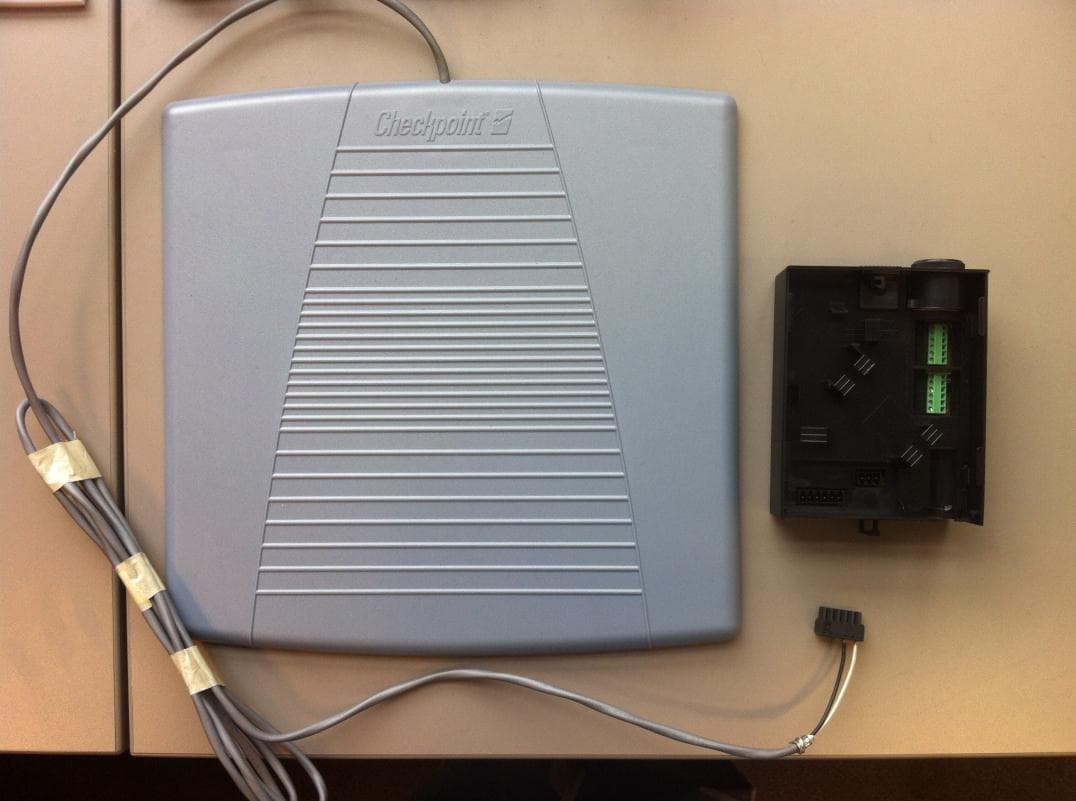
Click to zoom
Application Details
- Equipment Class
- FAP - Part 15 Anti-Pilferage Device
- Date of Grant
- Apr 03, 2014
- Application Purpose
- Original Equipment
- Date of Application
- Apr 03, 2014
- Equipment Note
- Deactivator board
- Frequency Range
- 7.40000000 - 9.80000000
- Company
- Checkpoint Systems Inc
- Country
- United States
Documents & Files
Document Text
Text extracted from the exhibit documents filed with the FCC. Open a document above to read the original.
Users Manual
CKP P/N 10073883 Counterpoint iD Quick Start Guide Reference During Installation CPiD - Quick Start Guide Copyright © 2014 by Checkpoint Systems, Inc. All rights reserved. Checkpoint® is a registered trademark of Checkpoint Systems, Inc. Released March 21, 2014. Published by: Checkpoint Systems Inc. 101 Wolf Drive Thorofare, NJ 08086 For use with Checkpoint’s Counterpoint Intelligent Deactivation System. Checkpoint, Counterpoint, Evolve, VisiPlus and People Counter are registered trademarks of Checkpoint Systems, Inc. All rights reserved. Information in this document is subject to change without notice. Companies, names and data used in examples herein are fictitious unless otherwise noted. No part of the contents of this book may be reproduced or transmitted in any form or by any means without the written permission of the publisher. All other product or service names are the property of their respective owners. Document Revision Information Part Number: 10073883 RevDescriptionDateAuthors 00CR2642BMarch 21, 2014G. Plizak, B. Langer, R. Decker Quick Start Guide: Counterpoint iD Page 1 of 7 Installation Requirements What’s In The Box 1 CPiD Chassis 1 Power Supply Unit (PSU) Install kit including: 2 #8 hex head screws (5/8 inch long) 2 tie wraps 1 6-Pin connector To o l s R e q u i re d 1 small flathead screwdriver 1 1/4 inch nut driver Optional DMS Version 1.8.95 or later (required for setup of advanced features) Operation/Features Front 1SounderSounder for alarm annunciation 2Status LEDInforms the User about device status. LED Functions are defined in the label underneath the top plate. 3Power LED (Green only)Indicates power 4Volume KnobAdjusts sounder volume 5LatchAllows user to remove unit for installing external connections (e.g., cable for Antenna Pad, key switch or lock/trigger) 6Rubber BootConceals DIP Switches, Reset Button and DMS Connection port Checkpoint Systems, Inc. – Field Service Installation Document – CKP P/N 10073883 Page 2 of 7 Rear Inside This is what you find, pre-install with chassis cover (plate) removed. 1Input Power ConnectorConnector for +12V DC input power 2DC Jack Strain ReliefStrain relief for power cord 3Internal Cabling exitOpening for all cables that connect internally (e.g., Antenna Cable) 4USB ConnectorConnector for future USB functionality 1Antenna 1 and 2 Primary RF Connection for 2 antennas max. (parallel) Pin-out1ANT2+ 2GND 3ANT2- 4ANT1+ 5GND 6ANT1- 2Antenna 3Secondary RF Connection for another supported antenna Pin-out1ANT3+ 2GND 3ANT3- Quick Start Guide: Counterpoint iD Page 3 of 7 DIP Switch Functions 3Alarm and InterlockConnection for Interlock and Alarm Interlock Description / Pin-out Interlocks are external devices that relay control signals to the device 1Interlock Input. Default is shorted to Pin 2 using wire jumper 2GND 3Interlock Opto, polarity independent (jumper must be removed prior to use). 4Interlock Opto, polarity independent (jumper must be removed prior to use) Alarm Description / Pin-out The alarm output supports generic sounder devices and external LEDs 5+12V 6Alarm - 4+12V Auxiliary Output and GPIO Connection for GPIO and +12V output GPIO Description / Pin-out General Purpose Input Output 1GPO RLY, 1A max resistive load 2GPO RLY, 1A max resistive load 3GPI+, 3.3V through 10k Ohm 4GND +12V Description / Pin-out This set of terminal pins is used to connect devices that require 12V 5+12V, 100mA max 6GND SelectionSwitch 1SelectionSwitch 2Switch 3SelectionSwitch 4Switch 5Switch 6 High PowerOFFMode 5OFFOFFMin GainOFFOFFOFF Low PowerONMode 6ONONGain 2OFFOFFON Mode 4OFFONGain 3OFFONOFF VerificationONOFFGain 4OFFONON Gain 5ONOFFOFF Gain 6ONOFFON Gain 7ONONOFF Max GainONONON Checkpoint Systems, Inc. – Field Service Installation Document – CKP P/N 10073883 Page 4 of 7 Status LED Functions *Future Release Reset Button This button resets the unit and auto-tunes the antenna under certain conditions. See Tuning on page 7. DMS Setup Some features of CPiD are able to adjusted / applied without DMS, others are not. For example, DMS is required to enable the secondary transmitter. (Click here for FSWP link. Download DMS Version 1.8.95 or later.) GPIO The default system configuration has the following GPIO functions: • GPO – Primary Alarm Relay • GPI – Disabled Any other functionality needs require DMS. Status LED FunctionRedYellowBlueTealWhiteVioletGreen Detection (Tag Alarm)X Waiting for InterlockX Keyswitch disabledX AutoTuneBlink Auto Tune Window 0.5s after reset is pressed Auto Tune ErrorX Antenna OvervoltageBlink MistunedBlinkBlink Verification ModeX Mode 4X* Mode 5X* Mode 6X* Factory Default Settings Blink at power up Quick Start Guide: Counterpoint iD Page 5 of 7 Mounting A secure location, such as behind an access door below the register, is ideal for mounting. Plan routing and location so the unit will not be struck by anything. When possible, locate unit such that user has ability to interface with device. Consult the SOW when provided. Customer may prefer / request no access. Volume can only be muted in DMS. Choose 1 of the following orientations: Figure 1: Typical Orientations Top plate has front and rear. Install with edge in rear (away from user). User can remove entire chassis to change configuration or adjust power. If mounting permanently, install 2 hex head screws using top plate as a template for the 2 screw locations. • Do not install chassis with front against a surface that can block access or prevent assembly. • Always release the front latch to remove the chassis or top plate. • View front labels to ensure unit will achieve correct orientation. An easy visual cue is with the Sounder on the left. Checkpoint Systems, Inc. – Field Service Installation Document – CKP P/N 10073883 Page 6 of 7 Wiring Procedure 1. Connect antenna cable(s) according to Table on page 2. Plug into ANT1 ANT2 connector, then route cable(s) through the clips for strain relief. Dog-bone excess antenna cable with provided tie wrap. Figure 2: Antenna Wiring…
Text truncated - open the document above for the full version.
Attestation Statements
Date: March 7, 2014 Re: A list of antennas to be used with Counterpoint iD Deactivator Below is a list of antennas that represent various sizes and material e.g. wire, circuit board, copper to be used with Counterpoint iD Deactivator. Antenna sizes will vary depending on the application of the device. Checkpoint selected 12”x12” antenna pad which produces the largest field strength. Antenna Type Antenna Structure Antenna Size Counterpoint pad 1 turn loop 12” x 12” Royston antenna 1 turn loop 13” x 6” NCR 7876 2 turn loop 8.5” x 6.5” NCR 7878 1 turn loop 6” x 6” Conveyor Deactivation Pad 1 turn loop 9.8” x 9.8” Handheld deactivator 1 turn loop 10” x 8” Hand scan antenna 1 turn loop 6.8” x 1.5” Sheet deactivator 1 turn loop 9.4” x 9.4” Magellan 8400/9800 1 turn loop 8” x 8” Metrologic MS2420 1 turn loop 8” x 8” Motorola MP6000 1 turn loop 8” x 8” Sincerely, Shawn Singh Regulatory Compliance Engineer Checkpoint Systems, Inc. Worldwide Headquarters 101 Wolf Drive Thorofare, NJ 08080 USA Tel. +1.856.384.2344 [email protected] www.checkpointsystems.com
Cover Letter(s)
Checkpoint Systems, Inc. 121611-20a March 24, 2014 RE: CPiD antenna connector To Whom It May Concern: This letter is to state that the antenna connector internal to CPiD will be installed at the factory or professionally installed in the field. Any version of this installed by non professional would have an adapter cable preconnected to the internal antenna connector. Adapter cable would have a unique antenna connector on one end. Sincerely, Shawn Singh Regulatory Compliance Engineer Checkpoint Systems, Inc. Worldwide Headquarters 101 Wolf Drive Thorofare, NJ 08086 Tel. +1.856.384.2344 [email protected]
External Photos
Host / Antenna - Top Host Top (Closeup) Host Bottom Host Bottom (Without Cover) Host Rear Host Front Antenna Bottom Power Adapter Bottom Power Adapter Top
External Photos
RJ12 Antenna Connector Configuration Molex Connector Configuration
Internal Photos
Module – Top Board Module – Bottom Board Antenna - Internal
Test Report
FCC CFR47 PART 15 SUBPART C INDUSTRY CANADA RSS-210 ISSUE 8 CERTIFICATION TEST REPORT FOR DEACTIVATOR BOARD MODEL NUMBER: COUNTERPOINT ID FCC ID: DO4CPID IC: 3356B-CPID REPORT NUMBER: 10181914B ISSUE DATE: 2014-04-02 Prepared for CHECKPOINT SYSTEMS 101 WOLF DRIVE THOROFARE NJ, 08086, USA Prepared by UL LLC 1285 WALT WHITMAN RD. MELVILLE, NY 11747, U.S.A. TEL: (631) 271-6200 FAX: (877) 854-3577 REPORT NO: 10181914B DATE: 2014-04-02 FCC ID: DO4CPID IC: 3356B-CPID Page 2 of 47 UL LLC FORM NO: CCSUP4701D 1285 WALT WHITMAN RD, MELVILLE, NY 11747, USA TEL: (631) 271-6200 FAX: (877) 854-3577 This report shall not be reproduced except in full, without the written approval of UL LLC Revision History Rev. Issue Date Revisions Revised By -- 2/21/14 Initial Issue M. Antola A 3/7/14 Revised model number M. Antola B 4/2/14 Updated radiated emissions data M. Antola REPORT NO: 10181914B DATE: 2014-04-02 FCC ID: DO4CPID IC: 3356B-CPID Page 3 of 47 UL LLC FORM NO: CCSUP4701D 1285 WALT WHITMAN RD, MELVILLE, NY 11747, USA TEL: (631) 271-6200 FAX: (877) 854-3577 This report shall not be reproduced except in full, without the written approval of UL LLC TABLE OF CONTENTS 1. ATTESTATION OF TEST RESULTS ................................................................................. 4 2. TEST METHODOLOGY ..................................................................................................... 5 3. FACILITIES AND ACCREDITATION ................................................................................. 5 4. CALIBRATION AND UNCERTAINTY ................................................................................ 5 4.1. MEASURING INSTRUMENT CALIBRATION .............................................................. 5 4.2. SAMPLE CALCULATION ............................................................................................ 5 4.3. MEASUREMENT UNCERTAINTY ............................................................................... 5 5. EQUIPMENT UNDER TEST ............................................................................................... 6 5.1. DESCRIPTION OF EUT .............................................................................................. 6 5.2. DESCRIPTION OF AVAILABLE ANTENNAS .............................................................. 7 5.3. SOFTWARE AND FIRMWARE .................................................................................... 7 5.4. WORST-CASE CONFIGURATION AND MODE .......................................................... 7 5.5. MODIFICATIONS ........................................................................................................ 8 5.6. DESCRIPTION OF TEST SETUP ................................................................................ 8 6. TEST AND MEASUREMENT EQUIPMENT ......................................................................10 7. DUTY CYCLE ....................................................................................................................12 8. 6dB BANDWIDTH .............................................................................................................15 9. 99% BANDWIDTH .............................................................................................................17 10. RADIATED EMISSION TEST RESULTS .......................................................................19 10.1. LIMITS AND PROCEDURE .....................................................................................19 10.1.1. FUNDAMENTAL AND SPURIOUS EMISSIONS (0.009 – 30 MHz) ..................21 10.1.2. TX SPURIOUS EMISSION 30 TO 1000 MHz (LOW CHANNEL) ......................25 10.1.3. TX SPURIOUS EMISSION 30 TO 1000 MHz (HIGH CHANNEL) .....................27 11. AC MAINS LINE CONDUCTED EMISSIONS ................................................................29 12. SETUP PHOTOS ...........................................................................................................41 REPORT NO: 10181914B DATE: 2014-04-02 FCC ID: DO4CPID IC: 3356B-CPID Page 4 of 47 UL LLC FORM NO: CCSUP4701D 1285 WALT WHITMAN RD, MELVILLE, NY 11747, USA TEL: (631) 271-6200 FAX: (877) 854-3577 This report shall not be reproduced except in full, without the written approval of UL LLC 1. ATTESTATION OF TEST RESULTS COMPANY NAME: CHECKPOINT SYSTEMS 101 WOLF DRIVE THOROFARE, NJ, 08086, USA EUT DESCRIPTION: DEACTIVATOR BOARD MODEL: COUNTERPOINT ID SERIAL NUMBER: NON-SERIALIZED PRODUCTION UNIT DATE TESTED: 2/4/14 – 4/2/14 APPLICABLE STANDARDS STANDARD TEST RESULTS FCC PART 15 SUBPART C Pass INDUSTRY CANADA RSS-210 Issue 8, Annex 2 Pass INDUSTRY CANADA RSS-GEN Issue 3 Pass UL LLC tested the above equipment in accordance with the requirements set forth in the above standards, using test results reported in the test report documents referenced below and/or documentation furnished by the applicant. All indications of Pass/Fail in this report are opinions expressed by UL LLC based on interpretations of these calculations. The results show that the equipment is capable of demonstrating compliance with the requirements as documented in this report. Note: The results documented in this report apply only to the tested sample, under the conditions and modes of operation, as described by the referenced documents. This document may not be altered or revised in any way unless done so by UL LLC and all revisions are duly noted in the revisions section. Any alteration of this document not carried out by UL LLC will constitute fraud and shall nullify the document. This report must not be used by the client to claim product certification, approval, or endorsement by NVLAP, NIST, any agency of the Federal Government, or any agency of any government. Approved & Released For UL By: Tested By: Bob DeLisi Mike Antola WiSE Principal Engineer WiSE Project Lead UL UL REPORT NO: 10181914B DATE: 2014-04-02 FCC ID: DO4CPID IC: 3356B-CPID Page 5 of 47 UL LLC FORM NO: CCSUP4701D 1285 WALT WHITMAN RD, MELVILLE, NY 11747, USA TEL…
Text truncated - open the document above for the full version.
Test Setup Photos
REPORT NO: 10181914A DATE: 2014-03-07 FCC ID: DO4CPID IC: 3356B-CPID Page 41 of 47 UL LLC FORM NO: CCSUP4701D 1285 WALT WHITMAN RD, MELVILLE, NY 11747, USA TEL: (631) 271-6200 FAX: (877) 854-3577 This report shall not be reproduced except in full, without the written approval of UL LLC 12. SETUP PHOTOS BENCH TESTS BENCH TESTS REPORT NO: 10181914A DATE: 2014-03-07 FCC ID: DO4CPID IC: 3356B-CPID Page 42 of 47 UL LLC FORM NO: CCSUP4701D 1285 WALT WHITMAN RD, MELVILLE, NY 11747, USA TEL: (631) 271-6200 FAX: (877) 854-3577 This report shall not be reproduced except in full, without the written approval of UL LLC RADIATED EMISSION BELOW 30 MHz RADIATED EMISSIONS BELOW 30MHz (FRONT) REPORT NO: 10181914A DATE: 2014-03-07 FCC ID: DO4CPID IC: 3356B-CPID Page 43 of 47 UL LLC FORM NO: CCSUP4701D 1285 WALT WHITMAN RD, MELVILLE, NY 11747, USA TEL: (631) 271-6200 FAX: (877) 854-3577 This report shall not be reproduced except in full, without the written approval of UL LLC RADIATED EMISSIONS BELOW 30MHz (BACK) REPORT NO: 10181914A DATE: 2014-03-07 FCC ID: DO4CPID IC: 3356B-CPID Page 44 of 47 UL LLC FORM NO: CCSUP4701D 1285 WALT WHITMAN RD, MELVILLE, NY 11747, USA TEL: (631) 271-6200 FAX: (877) 854-3577 This report shall not be reproduced except in full, without the written approval of UL LLC RADIATED EMISSION ABOVE 30 MHz RADIATED EMISSIONS ABOVE 30 MHz (FRONT) REPORT NO: 10181914A DATE: 2014-03-07 FCC ID: DO4CPID IC: 3356B-CPID Page 45 of 47 UL LLC FORM NO: CCSUP4701D 1285 WALT WHITMAN RD, MELVILLE, NY 11747, USA TEL: (631) 271-6200 FAX: (877) 854-3577 This report shall not be reproduced except in full, without the written approval of UL LLC RADIATED EMISSIONS ABOVE 30 MHz (BACK) REPORT NO: 10181914A DATE: 2014-03-07 FCC ID: DO4CPID IC: 3356B-CPID Page 46 of 47 UL LLC FORM NO: CCSUP4701D 1285 WALT WHITMAN RD, MELVILLE, NY 11747, USA TEL: (631) 271-6200 FAX: (877) 854-3577 This report shall not be reproduced except in full, without the written approval of UL LLC AC MAINS LINE CONDUCTED EMISSION LINE CONDUCTED EMISSION (FRONT W/ANTENNA) LINE CONDUCTED EMISSION (FRONT W/TERMINATION) REPORT NO: 10181914A DATE: 2014-03-07 FCC ID: DO4CPID IC: 3356B-CPID Page 47 of 47 UL LLC FORM NO: CCSUP4701D 1285 WALT WHITMAN RD, MELVILLE, NY 11747, USA TEL: (631) 271-6200 FAX: (877) 854-3577 This report shall not be reproduced except in full, without the written approval of UL LLC END OF REPORT LINE CONDUCTED EMISSION (BACK W/ANTENNA) LINE CONDUCTED EMISSION (BACK W/TERMINATION)
Contact Information
Applicant
Nimesh Shah(R&D Director of Operations)
Test Firm
UL LLCRick Titus
Technical Specifications
| # | Rule Parts | Frequency Range | Power Output |
|---|---|---|---|
| 1 | 15C | 7.4 MHz - 9.8 MHz | - |
Other Applications from Checkpoint Systems Inc
DO4NS20
Sep 11, 2026EAS RF System
Equipment Class
DXX - Part 15 Low Power Communication Device TransmitterDO4WRTZ1550
Aug 19, 2026UHF-RFID Reader WRTZ-1550
Equipment Class
DSS - Part 15 Spread Spectrum TransmitterDO4EG35
Aug 06, 2026EAS RF Detection System
Equipment Class
DXX - Part 15 Low Power Communication Device TransmitterDO4EP30
Aug 05, 2026EAS RFDetection System
Equipment Class
DXX - Part 15 Low Power Communication Device TransmitterDO4NEO3NP
Mar 23, 2026Antenna Pedestal
Equipment Class
DXX - Part 15 Low Power Communication Device Transmitter