DO4FISOTPRFID SYSTEM
Checkpoint Systems Inc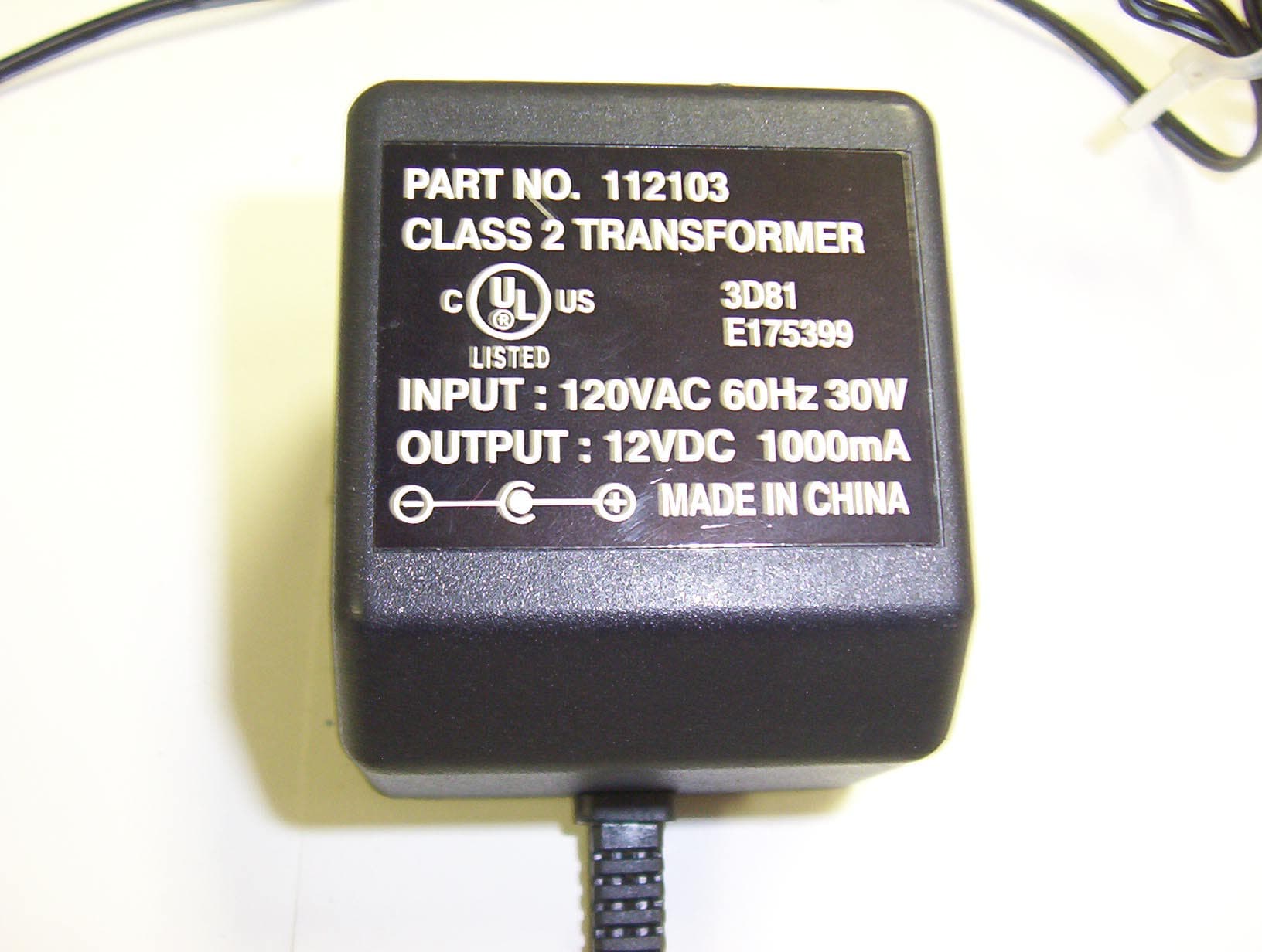
Click to zoom
Application Details
- Equipment Class
- DXX - Part 15 Low Power Communication Device Transmitter
- Date of Grant
- May 15, 2006
- Application Purpose
- Original Equipment
- Date of Application
- May 15, 2006
- Equipment Note
- RFID SYSTEM
- Frequency Range
- 13.56000000 - 13.56000000
- Company
- Checkpoint Systems Inc
- Country
- United States
Documents & Files
Document Text
Text extracted from the exhibit documents filed with the FCC. Open a document above to read the original.
External Photos
Power Supply top Power Supply Ferrite Front View Rear View Bottom View
External Photos
Front View Rear View Bottom View
Internal Photos
Top cover removed, antenna PCB removed Antenna Assembly Antenna PCB top A1072 PCB bottom A1072 PCB top
Internal Photos
Single Board Computer PCB bottom 1 Single Board Computer PCB bottom 2 Single Board Computer PCB top 1 Single Board Computer PCB top 2 Transmitter PCB bottom Transmitter PCB Top 1 Transmitter PCB Top 2
Internal Photos
Cover and Antenna Assembly removed to show component layout. Components are identical to Staff Station Reader Network Version
Test Report
VOJTZT! ! PCTC Product Compliance Test Center 2476 Swedesford Road, Malvern, PA 19355 ELECTROMAGNETIC INTERFERENCE TEST REPORT Doc. 20060320R/Project# 1304 TEST STANDARDS: 47 CFR PART 15, RSS-210 ISSUE 6, ICS-003 ISO ILS OPEN PLUS STAFF STATION READER AND STAFF STATION READER SERIAL VERSION FCC ID: DO4FISOTP / IC ID: 3356B-FISOTP CHECKPOINT SYSTEMS, INC. THOROFARE, NJ 08086 TEST DATES: March 9 th to March 20 th , 2006 ISSUE: April 12 th , 2006 Prepared by: Paul Banker Technical Staff Engineer Approved by: John Baumeister Group Manager, PCTC/ICC The results described in this report relate only to the item(s) tested. This document shall not be reproduced except in full without written permission of Unisys - PCTC. AMERICAN ASSOCIATION FOR LABORATORY ACCREDITATION Certificate No: 1028.01 VOJTZT! Page 2 of 23, 4/12/06 PCTC FCC ID: DO4FISOTP / IC ID: 3356B- FISOTP Product Compliance Test Center Doc. 20060320R/Project# 1304 ! PREFACE This report documents product testing conducted to verify compliance of the specified EUT with applicable standards and requirements as identified herein. EUT, test instrument configurations, test procedures and recorded data are generally described in this report. The reader is referred to the applicable test standards for detailed procedures. The following table summarizes the test results obtained during this evaluation. SUMMARY The ISO ILS Open Plus Staff Station Reader was tested to the standards listed below, and found to have the following characteristics: STANDARDS TEST FCC Industry Canada Frequency Range RESULT Radiated Emissions Intentional Radiator, Fundamental Part 15.223 RSS-210, A2.6 13.110 to 14.010 MHz Below Max. Permissible Limit Radiated Emissions Intentional Radiator, Harmonics Part 15.209 RSS-210, 2.7 10 MHz to 2 GHz Below Max. Permissible Limit Radiated Emissions Unintentional Radiator (Related to Digital Circuitry) Part 15.109 ICES-003 30 MHz to 2 GHz Below Max. Permissible Limit Conducted Emissions Unintentional & Intentional Radiators Part 15.207 RSS-Gen, 4.5 RSS-210, A2.6 13.110 to 14.010 MHz Below Max. Permissible Limit Frequency Stability Part 15.225 RSS-GEN 4.5 RSS-210, A2.6 13.110 to 14.010 MHz Below Max. Permissible Limit EUT Modifications: A clip-on ferrite (Fair-Rite p/n 044164151) was added to the DC line of the Staff Station Reader and the Serial Version. The DC line passes through the ferrite core six times. The Staff Station Reader also required the addition of Schlegel EMI gasket (p/n E9013T) around the perimeter of the junction between the top metal plate and the reader base. VOJTZT! Page 3 of 23, 4/12/06 PCTC FCC ID: DO4FISOTP / IC ID: 3356B- FISOTP Product Compliance Test Center Doc. 20060320R/Project# 1304 TABLE OF CONTENTS 1.0 Description of the Equipment Under Test (EUT) ..................................................................4 1.1 General Description .......................................................................................................................................4 1.2 Test Configurations........................................................................................................................................5 1.3 Rationale for the Chosen Configuration.........................................................................................................6 1.4 EUT Modifications ........................................................................................................................................6 2.0 Operation of the EUT During Testing ...................................................................................6 2.1 General...........................................................................................................................................................6 2.2 Operating Mode .............................................................................................................................................6 2.3 Rationale for the Chosen Mode of Operation ................................................................................................7 3.0 Applicable Requirements, Methods and Procedures .............................................................7 4.0 Test Results ............................................................................................................................8 4.1 Radiated Emissions ........................................................................................................................................8 4.1.1 Radiated Emissions Test Results (3/16/06)............................................................................................8 4.1.2 Occupied Bandwidth (3/8/06)..............................................................................................................10 ISO ILS Open Plus Staff Station Reader .......................................................................................10 4.2 Conducted Emissions...................................................................................................................................13 4.2.1 Conducted Emission Test Results (3/16/06) ........................................................................................13 4.3 Frequency Stability (3/21/06) ......................................................................................................................19 4.4 SAR Requirements.......................................................................................................................................22 Appendix A – Test Equipment List ...............................................................................................23 VOJTZT! Page 4 of 23, 4/12/06 PCTC FCC ID: DO4FISOTP / IC ID: 3356B- FISOTP Product Compliance Test Center Doc. 20060320R/Project# 1304 1.0 Description of the Equipment Under Test (EUT) ISO ILS Open Plus Staff Station Reader Equipment Identification Network Version Serial Version Serial Number 7591344B0P00416010 7403475B0P00416001 Manufac…
Text truncated - open the document above for the full version.
Test Setup Photos
VOJTZT! Page 13 of 23, 4/12/06 PCTC FCC ID: DO4FISOTP / IC ID: 3356B- FISOTP Product Compliance Test Center Doc. 20060320R/Project# 1304 Staff Station (Serial Version) Front Staff Station (Serial Version) Rear 4.2 Conducted Emissions Test Standards: USA: 47 CFR Part 15.207 Canada: RSS-GEN 7.2.2 Frequency Range: 150kHz to 30 MHz AC Power: 120 Vac, 60 Hz EUT Type: Table top Highest Oscillator Frequency: 400 MHz Measurement Uncertainty: 5.0 dB (CISPR 16-4: 2002) Conducted Emission Calculation: Peak Emission (dBuV Peak) = Meter reading (dBuV) + cable loss (dB) + Limiter loss (dB) 4.2.1 Conducted Emission Test Results (3/16/06) The conducted emissions recorded on the EUT AC power cord (s), displayed against the limits for CISPR 22, Class B devices are presented on the following pages. Conducted emission amplitudes (dBμV PK) measured with a peak detector are compared with CISPR 22, Class B average limit and displayed on the graph. Where the measured peak detector emission exceeded the average limit, or found to be within 1 dB of average limit, re-measurement using quasi-peak and average detector functions was made. The re-measured emissions are presented in a table below the appropriate table of peak detector emissions, which displays quasi-peak measurements vs. the quasi-peak limit and the average measurements vs. the average limit. A 50-ohm terminator was substituted for the EUT loop antenna in order to eliminate coupling of the fundamental signal onto the AC conductors of the Serial Version of the Staff Station Reader. VOJTZT! Page 18 of 23, 4/12/06 PCTC FCC ID: DO4FISOTP / IC ID: 3356B- FISOTP Product Compliance Test Center Doc. 20060320R/Project# 1304 Staff Station Reader: Conducted Emission Test Setup Staff Station Reader (Serial Version): Conducted Emission Test Setup Staff Station Reader (Serial Version): 50-ohm load on transmitter
Contact Information
Applicant
Nimesh Shah(R&D Director of Operations)
Test Firm
UNISYS CorporationJohn Baumeister
Technical Specifications
| # | Rule Parts | Frequency Range | Power Output |
|---|---|---|---|
| 1 | 15C | 13.56 MHz - 13.56 MHz | - |
Other Applications from Checkpoint Systems Inc
DO4NS20
Sep 11, 2026EAS RF System
Equipment Class
DXX - Part 15 Low Power Communication Device TransmitterDO4WRTZ1550
Aug 19, 2026UHF-RFID Reader WRTZ-1550
Equipment Class
DSS - Part 15 Spread Spectrum TransmitterDO4EG35
Aug 06, 2026EAS RF Detection System
Equipment Class
DXX - Part 15 Low Power Communication Device TransmitterDO4EP30
Aug 05, 2026EAS RFDetection System
Equipment Class
DXX - Part 15 Low Power Communication Device TransmitterDO4NEO3NP
Mar 23, 2026Antenna Pedestal
Equipment Class
DXX - Part 15 Low Power Communication Device Transmitter