DO4LIBUHXLiberty UHX Pedestals
Checkpoint Systems Inc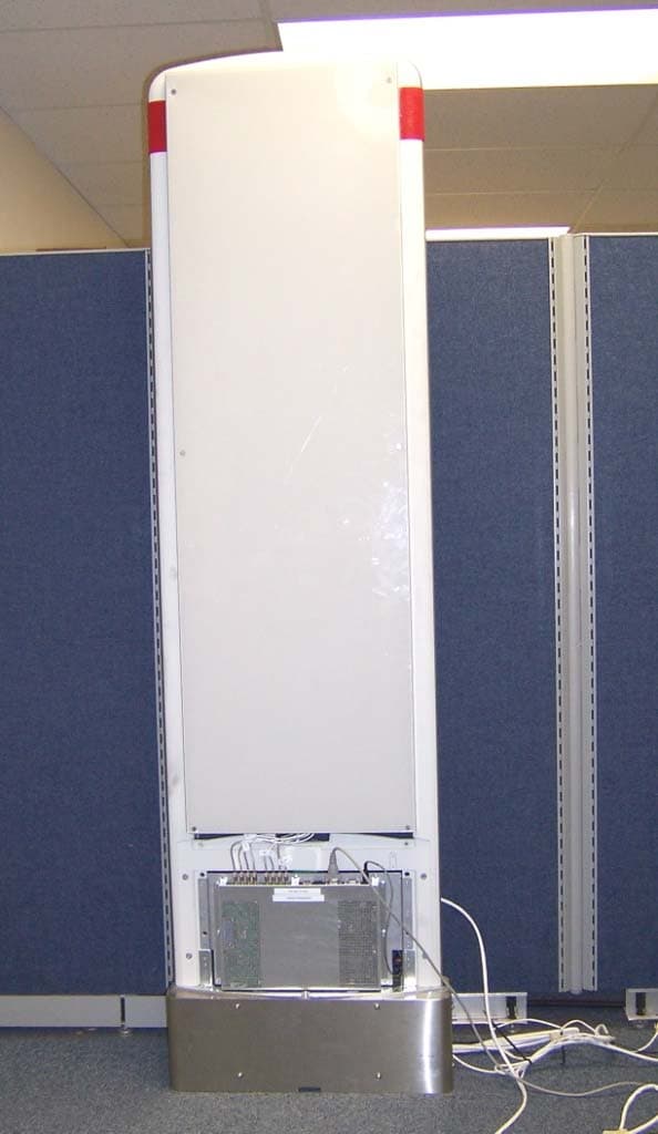
Click to zoom
Application Details
- Equipment Class
- DXX - Part 15 Low Power Communication Device Transmitter
- Date of Grant
- Apr 11, 2005
- Application Purpose
- Original Equipment
- Date of Application
- Apr 11, 2005
- Equipment Note
- Liberty UHX Pedestals
- Frequency Range
- 7.60000000 - 8.70000000
- Company
- Checkpoint Systems Inc
- Country
- United States
Documents & Files
Document Text
Text extracted from the exhibit documents filed with the FCC. Open a document above to read the original.
Users Manual
Liberty ™ UHX Pedestal for Retail Upgrade Guide iii Copyright © 2004 by Checkpoint Systems, Inc. Released May 6, 2005. Published by: Checkpoint Systems Inc. 101 Wolf Drive Thorofare, NJ 08086 Document revision information Upgrade Guide for the Liberty UHX Pedestals 4th Edition - 2-9-2005 5th Edition - 3-18-2005 6th Edition - 5-6-2005 Trademarks Checkpoint and Strata are a registered trademark and Liberty is a trademark of Checkpoint Systems, Inc. Other product and company names herein may be trademarks of their respective owners. Other products © or ® their respective manufacturers or copyright holders. Copyright and Warranty Information The information in this manual is subject to change without notice. Because of the changing nature of this product information presented in the Upgrade Guide, Checkpoint Systems, Inc. is not liable for any omissions, misstatements, or other errors of information. The information presented in the Upgrade Guide may not be copied, used or disclosed to others for the purpose of procurement or manufacturing without the written permission of Checkpoint Systems, Inc. This manual and the products discussed in this manual are the exclusive property of Checkpoint Systems Inc. Copyright laws of the United States protect all information and products. Copyright© 2001, 2002, 2003 and 2004 Checkpoint Systems, Inc. All rights reserved. iv Important Information to our Users in North America FCC Regulatory Compliance Statement Checkpoint Systems, Inc., offers Radio Frequency Identification Products that have been FCC certified or verified to 47 CFR Part 15 Subparts B/C and/or 47 CFR Part 18. Appropriately, one of the following labels will apply to the approval: NOTE: This equipment has been tested and found to comply with the limits for a class A digital device, pursuant to Part 15 of the FCC Rules. These limits are designed to provide reasonable protection against harmful interference when the equipment is operated in a commercial environment. This equipment generates, uses, and can radiate interference to radio communications. Operation of this equipment in a residential area is likely to cause harmful interference in which case the user will be required to correct the interference at his own expense. - OR - This device complies with Part 15 of the FCC Rules. Operation is subject to the following two conditions: (1) including this device may not cause harmful interference, and (2) this device must accept any interference received, including interference that may cause undesired operation, which may include intermittent decreases in detection and/or intermittent increases in alarm activity. - OR - NOTE: This equipment has been tested and found to comply with the limits for a miscellaneous type ISM device, pursuant to Part 18 of the FCC Rules. This equipment generates, uses, and can radiate radio frequency energy and, if not installed and used in accordance with the instruction manual, may cause harmful interference to radio communications. However, there is no guarantee that interference will not occur in a particular installation. If this equipment does cause harmful interference to radio communications reception, which can be determined by turning the equipment off and on, please contact Checkpoint Systems, Inc., at 1 (800) 257-5540 for further assistance. Equipment Safety Compliance Statement Checkpoint Systems Radio Frequency Identification products have been designed to be safe during normal use and, where applicable, certain components of the system or accessory sub-assemblies have been certified, listed or recognized in accordance with one or more of the following Safety standards: UL 1012, UL 1037, UL 1310, UL 60950-1, CSA C22.2 No. 205, CSA C22.2 No. 220, CSA C22.2 No. 223, CSA C22.2 No. 60950-1. Additional approvals may be pending. WARNING: Changes or modifications to Checkpoint’s Radio Frequency Identification (RFID) equipment not expressly approved by the party responsible for assuring compliance could void the user’s authority to operate the equipment in a safe or otherwise regulatory compliant manner. 1 Introduction1-1 Removing Existing Pedestals2-1 Removing QS2000 Pedestals 2-2 Estimated completion time 2-3 Removing bumper posts 2-3 Estimated completion time 2-3 Removing Strata PX Pedestals 2-4 Estimated completion time 2-5 Removing bumper posts 2-5 Estimated completion time 2-5 Removing Liberty PX Pedestals 2-6 Estimated completion time 2-7 Installing Liberty UHX Pedestals3-1 Cutting new wiring channel 3-1 Estimated completion time 3-1 Electrical and Network Wiring 3-2 Wiring for front entrance 3-3 Wiring for employee entrance pedestal 3-4 Estimated completion time 3-5 Installing the pedestal 3-6 Estimated completion time 3-7 Liberty UHX Installation Checklist4-1 Installation Checklist 4-1 General Information 4-1 Project Management/Marketing Scope 4-2 Checkpoint Contractor Scope 4-2 Checkpoint Technical Scope 4-2 Target Technical Scope 4-3 System Removal 4-3 System Installation 4-3 Follow up Procedures 4-4 Sample Door Layouts 4-7 Liberty UHX AR-400 Setup Instructions5-1 Equipment 5-1 Post-Installation Procedure 5-1 Verification of Power Settings 5-5 Table of Contents 2 1-1Liberty UHX Upgrade Guide CHAPTER CHAPTER 0INTRODUCTION This Guide allows you to upgrade existing installations of QS2000, Strata PX and Liberty PX pedestals to the new Liberty UHX pedestal. The new Liberty UHX pedestals can read both EAS and UHF/RFID tags simultaneously. The following upgrade scenarios are covered in this document: • Removing the existing pedestals •QS2000 pedestals (EAS) •Strata PX pedestals (EAS) •Liberty PX pedestals (EAS) • Installing the new Liberty UHX pedestals (EAS and RFID) •Cutting the new wiring channel •Installing the power supplies •Running the electrical and network wiring •Installing the new Liberty UHX pedestals An upgrade is completed by Checkpoint in an expeditious manner from the legacy pedestals without disruption to the store operations for extended…
Text truncated - open the document above for the full version.
Cover Letter(s)
American Telecommunications Certification Body Inc. 6731 Whittier Ave, McLean, VA 22101 April 7, 2005 RE: FCC ID: D04LIBUHX_ATCB002281 Attention: Gregory M. Snyder I have a few comments on this Application. Please note that further comments may arise in response to answers provided to the questions below. 1. Please note that the alignment of the block designations and the blocks is off on pages 9, 18, 28 and 31 of the operational description (Confidential_AR400US Operational Description.pdf). Please correct. 2. Please note that the manual does not appear to have any of the required FCC statements (i.e. 15.21 and 15.105). Please provide a manual with all required FCC statements. 3. Please note that the operational description mentions use at frequencies not approved for US operation. These frequencies are listed for EU operation. Please note that 15.5 states that a device under part 15 cannot be manufactured with user accessible controls of functions that allow the device to operate on non-US frequencies. Please verify that the US product as sold in the US cannot be made to operate on any non-US frequency. 4. Please note that the FHSS device operational description mentions “CW differential drive level”. Also, please note that the operational description mentions CW. Please verify that this is not an indication that the FHSS device transmits only a CW signal at some point. Please note that this would not be allowed as it would not meet the definition of a FHSS device (mainly – a spread spectrum system in which the carrier is modulated with the coded information in a conventional manner causing a conventional spreading of the RF energy about the frequency carrier.) 5. FYI – the operational description should be for US only products and need not consider other countries. 6. Please note that the operational description states the output of the device is 1W yet the 731 and test report state the output is only 0.491W. Please be consistent in the documentation. Please correct the appropriate documents to reflect the actual power of the device as will be granted. 7. Please note that the 731 states the device is seeking certification under 15.225. Please note that the particular frequency allocation under 15.225 is between 13.11 and 14.01MHz. The frequency listed on the 731 is 7.6 to 8.7MHz range. Please provide a 731 that accurately reflects the device in question. Please also include the field strength level for this frequency range on the 731. 8. Please note that MPE is only good for devices that are greater than 20cm from the person. Thus, calculating a ‘safe’ distance less than 20cm has no meaning. Please provide the level MPE at 20cm in the MPE report. 9. Page 8 of the schematics (Confidential_LIBUHX Schematics.pdf) appear to mention filtering at 13.6MHz. The report states the device operates in the 8MHz range. Please explain. 10. Please provide some additional information on the algorithm used to determine the pseudo- random hopping sequence to show that the hopping sequence is truly pseudo-random. Dennis Ward mailto:[email protected] The items indicated above must be submitted before processing can continue on the above referenced application. Failure to provide the requested information may result in application termination. Correspondence should be considered part of the permanent submission and may be viewed from the Internet after a Grant of Equipment Authorization is issued. z Page 2 April 7, 2005 Please do not respond to this correspondence using the email reply button. In order for your response to be processed expeditiously, you must submit your documents through the AmericanTCB.com website. Also, please note that partial responses increase processing time and should not be submitted. Any questions about the content of this correspondence should be directed to the sender.
Cover Letter(s)
Response to ATCB Comments FCC ID: D04LIBUHX 1 Washington Laboratories, Ltd. 7560 LINDBERGH DRIVE GAITHERSBURG, MD 20879 (301) 417 – 0220 FAX # (301) 417 - 9069 April 11, 2005 Mr. Dennis Ward American Telecommunications Certification Body Inc. 6731 Whittier Ave McLean, VA 22101 RE: Comments of April 6, 2005 APPLICATION: D04LIBUHX Checkpoint Systems, Inc. Dear Mr. Ward: Below are the comments that you have provided regarding the application for certification referenced above. Our responses to those comments are in bold italic. Many responses refer you to additional exhibit(s) which has been uploaded to the application folder at the ATCB website. Thank you for your attention. Please feel free to contact us for any additional information that you may require. Regards, Gregory M. Snyder Chief EMC Engineer, Wireless/Telco Services Manager Brian J. Dettling Documentation Specialist WLL Project: 8602 1) Please note that the alignment of the block designations and the blocks is off on pages 9, 18, 28 and 31 of the operational description (Confidential_AR400US Operational Description.pdf). Please correct. R. The Operational Description for the AR400 does not convert to pdf form correctly. The original “Word” document has been uploaded. See exhibit “AR400US Operational Description.doc”. 2) Please note that the manual does not appear to have any of the required FCC statements (i.e. 15.21 and 15.105). Please provide a manual with all required FCC statements. R. The User Manual has been amended to include regulatory information. Please see “LIBUHX User Manual revised.pdf”. Response to ATCB Comments FCC ID: D04LIBUHX 2 3) Please note that the operational description mentions use at frequencies not approved for US operation. These frequencies are listed for EU operation. Please note that 15.5 states that a device under part 15 cannot be manufactured with user accessible controls of functions that allow the device to operate on non-US frequencies. Please verify that the US product as sold in the US cannot be made to operate on any non-US frequency. R. We assume you are referring to the AR400 component. The description covers all versions available from the manufacturer. The US product is sold to only function in the US allocated frequencies and can not be changed to operate on non-US frequencies. This device was originally approved by ATCB in June 2004 (PYFAR400US). 4) Please note that the FHSS device operational description mentions “CW differential drive level”. Also, please note that the operational description mentions CW. Please verify that this is not an indication that the FHSS device transmits only a CW signal at some point. Please note that this would not be allowed as it would not meet the definition of a FHSS device (mainly – a spread spectrum system in which the carrier is modulated with the coded information in a conventional manner causing a conventional spreading of the RF energy about the frequency carrier.) R. The FHSS device does not transmit CW. Only data (modulated signal) is transmitted at all times. 5) FYI – the operational description should be for US only products and need not consider other countries. R. Noted. 6) Please note that the operational description states the output of the device is 1W yet the 731 and test report state the output is only 0.491W. Please be consistent in the documentation. Please correct the appropriate documents to reflect the actual power of the device as will be granted. R. The FHSS device has a selectable power from 31.6mW up to 1 Watt as approved under FCC ID: PYFAR400US. However, this application fixes the output power to 0.491W and cannot be adjusted. The device as used in this application is limited to the level indicated on the 731 form. 7) Please note that the 731 states the device is seeking certification under 15.225. Please note that the particular frequency allocation under 15.225 is between 13.11 and 14.01MHz. The frequency listed on the 731 is 7.6 to 8.7MHz range. Please provide a 731 that accurately reflects the device in question. Please also include the field strength level for this frequency range on the 731. R. This typographical error has been corrected, and the additional information provided. Please see “LIBUHX Application Form corrected.pdf”. 8) Please note that MPE is only good for devices that are greater than 20cm from the person. Thus, calculating a ‘safe’ distance less than 20cm has no meaning. Please provide the level MPE at 20cm in the MPE report. R. The RF Exposure Evaluation has been done as a fixed installation. Please reference e-mail from Tim Harrington regarding this device. Also, this issue has been extensively discussed amongst Tim Johnson, Tim Harrington, Greg Sleet and myself. You may like to consult with Tim Johnson regarding this subject. 9) Page 8 of the schematics (Confidential_LIBUHX Schematics.pdf) appear to mention filtering at Response to ATCB Comments FCC ID: D04LIBUHX 3 13.6MHz. The report states the device operates in the 8MHz range. Please explain. R. This indicates the cut-off point of the filter, not the transmitting frequency. 10) Please provide some additional information on the algorithm used to determine the pseudorandom hopping sequence to show that the hopping sequence is truly pseudo-random. R. We assume you are referring to the AR400 module. This device was approved by ATCB in June 2004 (FCC ID PYFAR400US) and no changes have occurred to the information originally submitted. The submitted information shows the pseudorandom hopping sequence.
External Photos
Liberty UHX With Covers In Place AR400 Side, Cover Removed EAS Side, Cover Removed
Internal Photos
Board A Top Board A Bottom Board B Top Board B Bottom AR400 Shield On AR400 Shield Off AR400 Side A AR400 Side B AR400 Antenna Side A AR400 Antenna Side B EAS Antenna Loop EAS Shield On EAS Shield Off EAS Bottom
Test Report
Document 8602-01, Rev. 0 FCC ID: DO4LIBUHX FCC Certification Test Report Washington Laboratories, Ltd April 2005 FCC Certification Test Report for Checkpoint Systems Inc. Liberty UHX RFID System FCC ID: DO4LIBUHX April 4, 2005 Prepared for: Checkpoint Systems Inc. 101 Wolf Drive Thorofare, NJ 08086 Prepared By: Washington Laboratories, Ltd. 7560 Lindbergh Drive Gaithersburg, Maryland 20879 FCC Certification Test Report Document 8602-01, Rev. 0 FCC ID: DO4LIBUHX FCC Certification Test Report Washington Laboratories, Ltd April 2005 FCC Certification Test Report for the Checkpoint Systems Inc. Liberty UHX RFID System FCC ID: DO4LIBUHX April 4, 2005 WLL JOB# 8602 Prepared by: Brian J. Dettling Documentation Specialist Reviewed by: Gregory M. Snyder Chief EMC Engineer Document 8602-01, Rev. 0 FCC ID: DO4LIBUHX FCC Certification Test Report Washington Laboratories, Ltd April 2005 ii Abstract This report has been prepared on behalf of Checkpoint Systems Inc. to support the attached Application for Equipment Authorization. The test report and application are submitted for a co-located Frequency Hopping Spread Spectrum Transmitter under Part 15.247 and an EAS system operating at 8.2MHz under Part 15.223 of the FCC Rules. This Certification Test Report documents the test configuration and test results for the Checkpoint Systems Inc. Liberty UHX RFID System. Testing was performed on an Open Area Test Site (OATS) of Washington Laboratories, Ltd, 7560 Lindbergh Drive, Gaithersburg, MD 20879. Site description and site attenuation data have been placed on file with the FCC's Sampling and Measurements Branch at the FCC laboratory in Columbia, MD. Washington Laboratories, Ltd. has been accepted by the FCC and approved by NIST NVLAP (NVLAP Lab Code: 200066-0) as an independent FCC test laboratory. The Checkpoint Systems Inc. Liberty UHX RFID System complies with the limits for a low power intentional radiator under FCC Part 15.223 and a Frequency Hopping Spread Spectrum Transmitter device under FCC Part 15.247. Document 8602-01, Rev. 0 FCC ID: DO4LIBUHX FCC Certification Test Report Washington Laboratories, Ltd April 2005 iii Table of Contents Abstract ............................................................................................................................... ii 1 Introduction..............................................................................................................1 1.1 Compliance Statement .........................................................................................1 1.2 Test Scope ............................................................................................................1 1.3 Contract Information............................................................................................1 1.4 Test Dates ............................................................................................................1 1.5 Test and Support Personnel .................................................................................1 2 Equipment Under Test .............................................................................................2 2.1 EUT Identification & Description .......................................................................2 2.2 Test Configuration ...............................................................................................4 2.3 Testing Algorithm................................................................................................4 2.4 Test Location .......................................................................................................4 2.5 Measurements ......................................................................................................5 2.5.1 References........................................................................................................5 2.6 Measurement Uncertainty....................................................................................5 3 Test Equipment ........................................................................................................6 4 Test Results ..............................................................................................................7 4.1 Occupied Bandwidth: (FCC Part §2.1049, §15.223, §15.247) ............................7 4.2 Operation Within the Restricted Band: (FCC Part §15.205(d)(1))....................11 4.3 Number of Hopping Frequencies: (FCC Part §15.247(a)(1)(i)) ........................11 4.4 Carrier Frequency Separation: (FCC Part §15.247(a)(1)) .................................12 4.5 Time of Occupancy and Duty Cycle Correction: (FCC Part §15.247(a)(1)(i)).13 4.6 RF Power Output: (FCC Part §2.1046 and §15.247).........................................17 4.7 Conducted Spurious Emissions at Antenna Terminals (FCC Part §2.1051 and §15.247) .........................................................................................................................20 4.8 Radiated Spurious Emissions: RFID System (FCC Part §2.1053, §15.247) .....35 4.8.1 Test Procedure.............................................................................................35 4.9 Radiated Spurious Emissions: EAS System (FCC Part §2.1053, §15.223) ......41 4.9.1 Test Procedure.............................................................................................41 4.10 AC Powerline Conducted Emissions: (FCC Part §15.207) ...............................43 4.11 Checkpoint/FCC Correspondence Fax ..............................................................45 List of Tables Table 1. Device Summary................................................................................................... 3 Table 2: Test Equipment List.............................................................................................. 6 Table 3. Occupied Bandwidth Results.............................................................................. 10 Table 4. RF Power Output ..............................…
Text truncated - open the document above for the full version.
Test Setup Photos
Radiated Emissions Conducted Emissions
Contact Information
Applicant
Nimesh Shah(R&D Director of Operations)
Technical Contact
Washington Laboratories, Ltd.Gregory M Snyder
7560 Lindbergh Drive · Gaithersburg, Maryland · United States
Test Firm
Washington Laboratories, Ltd.Michael Violette
Technical Specifications
| # | Rule Parts | Frequency Range | Power Output |
|---|---|---|---|
| 1 | 15C | 7.6 MHz - 8.7 MHz | - |
Other Applications from Checkpoint Systems Inc
DO4NS20
Sep 11, 2026EAS RF System
Equipment Class
DXX - Part 15 Low Power Communication Device TransmitterDO4WRTZ1550
Aug 19, 2026UHF-RFID Reader WRTZ-1550
Equipment Class
DSS - Part 15 Spread Spectrum TransmitterDO4EG35
Aug 06, 2026EAS RF Detection System
Equipment Class
DXX - Part 15 Low Power Communication Device TransmitterDO4EP30
Aug 05, 2026EAS RFDetection System
Equipment Class
DXX - Part 15 Low Power Communication Device TransmitterDO4NEO3NP
Mar 23, 2026Antenna Pedestal
Equipment Class
DXX - Part 15 Low Power Communication Device Transmitter