DO4NCPRW7000ILS Non-contact Programmer
Checkpoint Systems Inc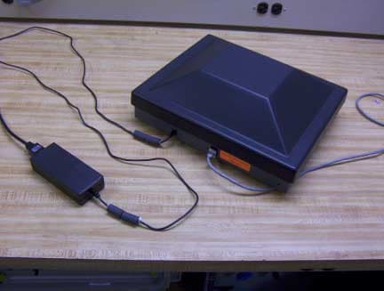
Click to zoom
Application Details
- Equipment Class
- FAP - Part 15 Anti-Pilferage Device
- Date of Grant
- Apr 25, 2004
- Application Purpose
- Original Equipment
- Date of Application
- Mar 16, 2004
- Equipment Note
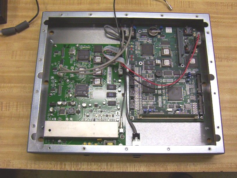
- ILS Non-contact Programmer
- Frequency Range
- 13.56000000 - 13.56000000
- Company
- Checkpoint Systems Inc
- Country
- United States
Documents & Files
Document Text
Text extracted from the exhibit documents filed with the FCC. Open a document above to read the original.
Users Manual
User Guide for the Non-Contact Programmer 3/17/2004 1 Section 1 – Loading the application 1. Start the Checkpoint RW Tag Programmer application. 2. Click on File and then on Load Tag Format. 3. Choose the tag format file created for you by Checkpoint Systems. If you are programming your existing barcodes into the circulation circuits, skip to Section 2. If you are having the application auto-increment your item identifiers, skip to Section 3. User Guide for the Non-Contact Programmer 3/17/2004 2 Section 2 – Using existing barcode identifiers 1. Place circulation circuit on the material to be tagged. 2. Scan the barcode on the material using the barcode scanner. User Guide for the Non-Contact Programmer 3/17/2004 3 3. Pass the material needing to be programmed over the non-contact programmer. The item identifier will now be programmed into the circulation circuit. User Guide for the Non-Contact Programmer 3/17/2004 4 4. Pass the material over the non-contact programmer again to verify the item identifier programmed into the circulation circuit matches the barcode identifier. User Guide for the Non-Contact Programmer 3/17/2004 5 Section 3 – Auto incrementing the item identifier 1. Click on the New Start button. 2. Enter in the starting value for your barcode sequence. Click on OK. 3. If you are programming multiple tags, click on Auto-Write Enabled. User Guide for the Non-Contact Programmer 3/17/2004 6 4. Click on Program A Tag. 5. Place the circulation circuit on the material to be tagged. User Guide for the Non-Contact Programmer 3/17/2004 7 6. Pass the material over the non-contact programmer. The item identifier will now be programmed into the circulation circuit. 7. To program another circulation circuit, simply insert the tag into the material and pass it over the non-contact programmer. User Guide for the Non-Contact Programmer 3/17/2004 8 8. To verify the item identifier programmed into the circulation circuit, uncheck Auto-Write Enabled, and pass the materials over the non-contact programmer.
Cover Letter(s)
Page 1 of 1 ΥΝΙΣΨΣ PCTC Product Compliance Test Center 2476 Swedesford Road, Malvern, PA 19355 17 March 2004 20040318CL1 Federal Communications Commission EQUIPMENT APPROVAL SERVICES P.O Box 358315 Pittsburgh, PA 15251-5315 Subject: Confidentiality Statement for Checkpoint Systems ILS Non-contact Programmer. Dear Sir/Madam: The Checkpoint Systems, ILS Non-contact Programmer, FCC ID DO4NCPRW7000, (frequency is 13.56 MHz) was tested for EMI compliance for operating according to the FCC Part 15 Sections 15.207, 15.209 and 15.225 requirements. Based on the compliance results of this test, and the additional items submitted to support the application, please register the Checkpoint Systems ILS Non-contact Programmer, FCC ID DO4NCPRW7000, with the Federal Communications Commission. Please note that Checkpoint requests confidentiality on the block diagram, theory of operation and schematics of the ILS Non-contact Programmer. It is their desire to limit their competitor’s access to these items. Sincerely, Paul M. Banker Technical Staff Engineer Unisys Corpration (610) 648-3723 E-Mail: [email protected]
Test Report
VOJTZT! ! PCTC Product Compliance Test Center 2476 Swedesford Road, Malvern, PA 19355 ELECTROMAGNETIC INTERFERENCE TEST REPORT Doc. 20040104R Project No. 980 TEST STANDARDS: USA 47 CFR PART 15 ILS Non-contact Programmer 2.0 FCC ID: DO4NCPRW7000 CHECKPOINT SYSTEMS, INC. THOROFARE, NEW JERSEY TEST DATE: September 03 to September 22, 2003 ISSUE: January 10, 2004 Prepared by: Paul Banker Technical Staff Engineer Approved by: John Baumeister Group Manager, PCTC/ICC The results described in this report relate only to the item(s) tested. This document shall not be reproduced except in full without written permission of Unisys - PCTC. AMERICAN ASSOCIATION FOR LABORATORY ACCREDITATION Certificate No: 1028.01 ! VOJTZT! PCTC Page 2 of 22, 1/10/2004 Product Compliance Test Center Doc. 20040104R Project No. 980 FCC ID: DO4NCPRW7000 PREFACE This report documents product testing conducted to verify compliance of the specified EUT with applicable standards and requirements as identified herein. EUT, test instrument configurations, test procedures and recorded data are generally described in this report. The reader is referred to the applicable test standards for detailed procedures. The following table summarizes the test results obtained during this evaluation. SUMMARY The ILS Non-contact Programmer 2.0 was tested to the standards listed below, and found to have the following characteristics: TEST STANDARD Frequency Range RESULT Radiated Emissions Intentional Radiator, Fundamental FCC Part 15.225 13.553 to 13.567 MHz Below Max. Permissible Limit Radiated Emissions Intentional Radiator, Harmonics FCC Part 15.209 10 MHz to 1 GHz Below Max. Permissible Limit Radiated Emissions Unintentional Radiator (Related to Digital Circuitry) FCC Part 15.109 30 MHz to 1 GHz Below Max. Permissible Limit Conducted Emissions Unintentional & Intentional Radiators FCC Part 15.107 Part 15.207 150 kHz to 30 MHz Below Max. Permissible Limit Frequency Tolerance 47 CFR Part 15.225 13.553 – 13.567 MHz Within .01 % tolerance EUT Modifications Two ferrite cores were added to each end of the DC output line of the Deltron 11985A Adapter. MEASUREMENT UNCERTAINTY Measurement Type Measurement Distance Frequency Range Measurement Limit Expanded Combined Uncertainty Radio Disturbance 10 meters 30 MHz to 1 GHz Class A 4.3 dB Radio Disturbance 3 meters 30 MHz to 1 GHz Class B 4.3 dB Conducted Disturbance N/A 150 kHz to 30 MHz Class A or B 3.6 dB As all values of uncertainty are less than the CISPR/A/355/FDIS (CISPR 16-4/FDIS) recommendations, no adjustments to measured data presented in this report are required. VOJTZT! PCTC Page 3 of 22, 1/10/2004 Product Compliance Test Center Doc. 20040104R Project No. 980 FCC ID: DO4NCPRW7000 TABLE OF CONTENTS 1.0 Description of The Equipment Under Test (EUT) ................................................................ 4 1.1 General Description ...................................................................................................................................... 4 1.2 Test Configurations ....................................................................................................................................... 5 1.3 Rationale for The Chosen Configuration....................................................................................................... 6 1.4 EUT Modifications........................................................................................................................................ 6 2.0 Operation of The EUT During Testing ................................................................................. 7 2.1 General .......................................................................................................................................................... 7 2.2 Operating Mode ............................................................................................................................................ 7 2.3 Rationale for The Chosen Mode of Operation .............................................................................................. 7 3.0 Applicable Requirements, Methods and Procedures............................................................. 8 3.1 Applicable Requirements .............................................................................................................................. 8 3.2 Basic Test Methods and Procedures.............................................................................................................. 8 3.3 Deviations Or Exclusions From The Requirements And Standards .............................................................. 8 4.0 Test Results ........................................................................................................................... 8 4.1 Radiated Emissions ....................................................................................................................................... 8 4.1.1 Test Facility........................................................................................................................................... 8 4.1.2 Radiated Emissions Test Procedure ...................................................................................................... 9 4.1.3 Radiated Emissions Test Results (9/16 – 9/19/2003) .......................................................................... 10 4.2 Conducted Emissions .................................................................................................................................. 14 4.2.1 Conducted Emission Test Procedure................................................................................................... 14 4.2.2 Conducted Emissions Test Results (9/22/2003) ................................................................................. 14 4.3 Frequency Tolerance Test ........................................................................................................................... 17 4.3.1 Frequency Tol…
Text truncated - open the document above for the full version.
Test Report
VOJTZT! ! PCTC Product Compliance Test Center 2476 Swedesford Road, Malvern, PA 19355 ELECTROMAGNETIC INTERFERENCE TEST REPORT Doc. 20040104R Project No. 980 TEST STANDARDS: USA 47 CFR PART 15 ILS Non-contact Programmer 2.0 FCC ID: DO4NCPRW7000 CHECKPOINT SYSTEMS, INC. THOROFARE, NEW JERSEY TEST DATE: September 03 to September 22, 2003 ISSUE: January 10, 2004 Prepared by: Paul Banker Technical Staff Engineer Approved by: John Baumeister Group Manager, PCTC/ICC The results described in this report relate only to the item(s) tested. This document shall not be reproduced except in full without written permission of Unisys - PCTC. AMERICAN ASSOCIATION FOR LABORATORY ACCREDITATION Certificate No: 1028.01 ! VOJTZT! PCTC Page 2 of 22, 1/10/2004 Product Compliance Test Center Doc. 20040104R Project No. 980 FCC ID: DO4NCPRW7000 PREFACE This report documents product testing conducted to verify compliance of the specified EUT with applicable standards and requirements as identified herein. EUT, test instrument configurations, test procedures and recorded data are generally described in this report. The reader is referred to the applicable test standards for detailed procedures. The following table summarizes the test results obtained during this evaluation. SUMMARY The ILS Non-contact Programmer 2.0 was tested to the standards listed below, and found to have the following characteristics: TEST STANDARD Frequency Range RESULT Radiated Emissions Intentional Radiator, Fundamental FCC Part 15.225 13.553 to 13.567 MHz Below Max. Permissible Limit Radiated Emissions Intentional Radiator, Harmonics FCC Part 15.209 10 MHz to 1 GHz Below Max. Permissible Limit Radiated Emissions Unintentional Radiator (Related to Digital Circuitry) FCC Part 15.109 30 MHz to 1 GHz Below Max. Permissible Limit Conducted Emissions Unintentional & Intentional Radiators FCC Part 15.107 Part 15.207 150 kHz to 30 MHz Below Max. Permissible Limit Frequency Tolerance 47 CFR Part 15.225 13.553 – 13.567 MHz Within .01 % tolerance EUT Modifications Two ferrite cores were added to each end of the DC output line of the Deltron 11985A Adapter. MEASUREMENT UNCERTAINTY Measurement Type Measurement Distance Frequency Range Measurement Limit Expanded Combined Uncertainty Radio Disturbance 10 meters 30 MHz to 1 GHz Class A 4.3 dB Radio Disturbance 3 meters 30 MHz to 1 GHz Class B 4.3 dB Conducted Disturbance N/A 150 kHz to 30 MHz Class A or B 3.6 dB As all values of uncertainty are less than the CISPR/A/355/FDIS (CISPR 16-4/FDIS) recommendations, no adjustments to measured data presented in this report are required. VOJTZT! PCTC Page 3 of 22, 1/10/2004 Product Compliance Test Center Doc. 20040104R Project No. 980 FCC ID: DO4NCPRW7000 TABLE OF CONTENTS 1.0 Description of The Equipment Under Test (EUT) ................................................................ 4 1.1 General Description ...................................................................................................................................... 4 1.2 Test Configurations ....................................................................................................................................... 5 1.3 Rationale for The Chosen Configuration....................................................................................................... 6 1.4 EUT Modifications........................................................................................................................................ 6 2.0 Operation of The EUT During Testing ................................................................................. 7 2.1 General .......................................................................................................................................................... 7 2.2 Operating Mode ............................................................................................................................................ 7 2.3 Rationale for The Chosen Mode of Operation .............................................................................................. 7 3.0 Applicable Requirements, Methods and Procedures............................................................. 8 3.1 Applicable Requirements .............................................................................................................................. 8 3.2 Basic Test Methods and Procedures.............................................................................................................. 8 3.3 Deviations Or Exclusions From The Requirements And Standards .............................................................. 8 4.0 Test Results ........................................................................................................................... 8 4.1 Radiated Emissions ....................................................................................................................................... 8 4.1.1 Test Facility........................................................................................................................................... 8 4.1.2 Radiated Emissions Test Procedure ...................................................................................................... 9 4.1.3 Radiated Emissions Test Results (9/16 – 9/19/2003) .......................................................................... 10 4.2 Conducted Emissions .................................................................................................................................. 14 4.2.1 Conducted Emission Test Procedure................................................................................................... 14 4.2.2 Conducted Emissions Test Results (9/22/2003) ................................................................................. 14 4.3 Frequency Tolerance Test ........................................................................................................................... 17 4.3.1 Frequency Tol…
Text truncated - open the document above for the full version.
Contact Information
Applicant
Nimesh Shah(R&D Director of Operations)
Technical Contact
Checkpoint Systems, Inc.Gregory E Sleet
[email protected]856-384-2339
101 Wolf Drive · Thorofare, New Jersey · United States
Non-Technical Contact
Checkpoint Systems, Inc.Gregory E Sleet
[email protected]856-384-2339
Test Firm
UNISYS CorporationJohn Baumeister
Technical Specifications
| # | Rule Parts | Frequency Range | Power Output |
|---|---|---|---|
| 1 | 15C | 13.56 MHz - 13.56 MHz | - |
Other Applications from Checkpoint Systems Inc
DO4NS20
Sep 11, 2026EAS RF System
Equipment Class
DXX - Part 15 Low Power Communication Device TransmitterDO4WRTZ1550
Aug 19, 2026UHF-RFID Reader WRTZ-1550
Equipment Class
DSS - Part 15 Spread Spectrum TransmitterDO4EG35
Aug 06, 2026EAS RF Detection System
Equipment Class
DXX - Part 15 Low Power Communication Device TransmitterDO4EP30
Aug 05, 2026EAS RFDetection System
Equipment Class
DXX - Part 15 Low Power Communication Device TransmitterDO4NEO3NP
Mar 23, 2026Antenna Pedestal
Equipment Class
DXX - Part 15 Low Power Communication Device Transmitter