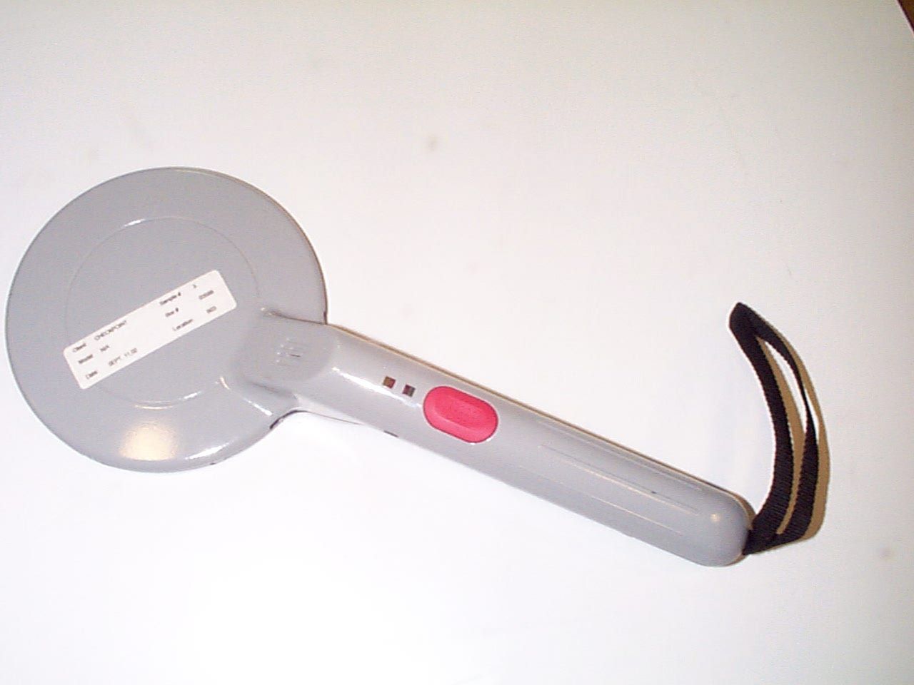
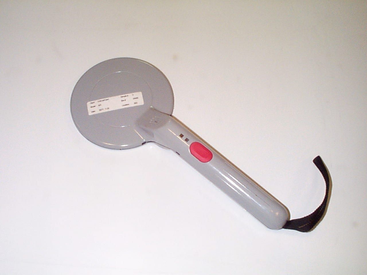
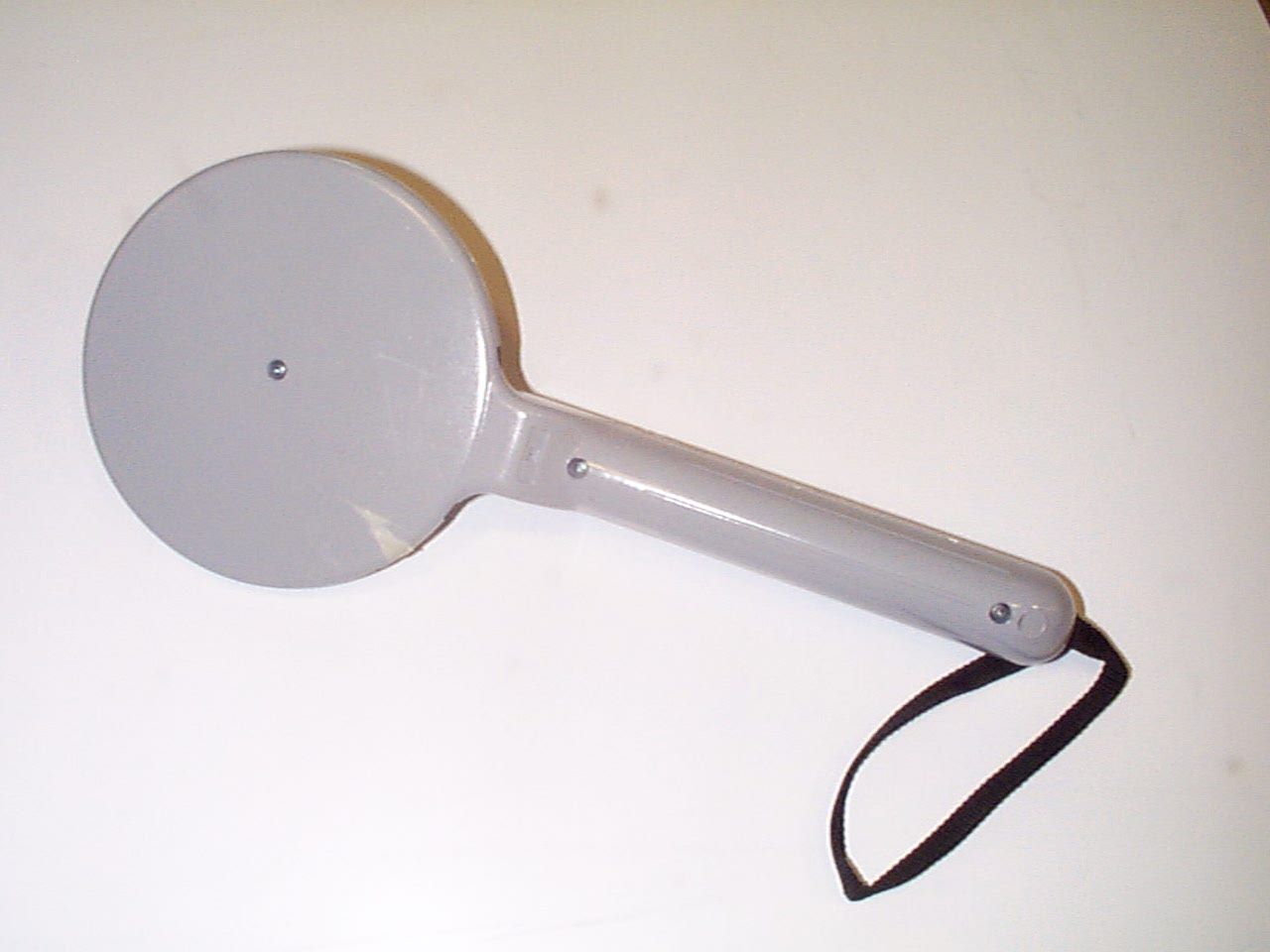
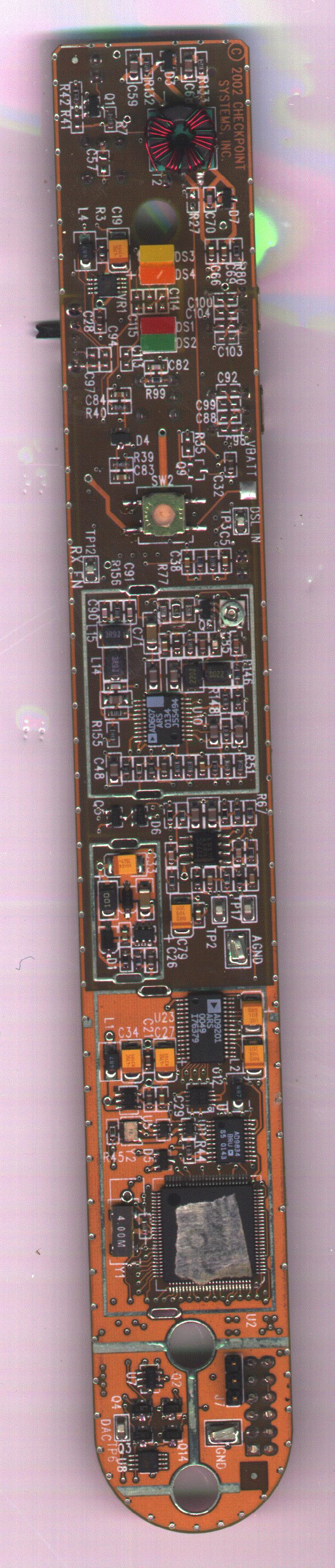
DO4OMNIPORTABLE ELECTRONIC ARTICLE SURVEILLANCE VERIFIER
Checkpoint Systems Inc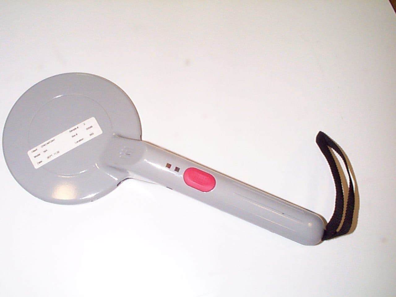
Click to zoom
Application Details
- Equipment Class
- DXT - Part 15 Low Power Transceiver, Rx Verified
- Date of Grant
- Feb 04, 2004
- Application Purpose
- Original Equipment
- Date of Application
- Feb 04, 2004
- Equipment Note
- PORTABLE ELECTRONIC ARTICLE SURVEILLANCE VERIFIER
- Frequency Range
- 15.48000000 - 17.50000000
- Company
- Checkpoint Systems Inc
- Country
- United States
Documents & Files

Document Text
Text extracted from the exhibit documents filed with the FCC. Open a document above to read the original.
Users Manual
363325 Rev. 01 Page 1 of 9 Omni Verifier User’s Manual 363325 Rev. 01Page 2 of 9 Packing List (see Figure 1) 1. Omni Verifier 2. Docking Station 3. Universal Power Supply 4. Mounting Hardware (2 screws and 2 wall anchors – shown in Figure 2) 5. Power cord (country specific - sold separately) 6. Deactivation Key (not shown - only available with the Omni Deactivation Package) 363325 Rev. 01Page 4 of 9 FIGURE 1 363325 Rev. 01Page 5 of 9 Installation of Docking Station Select a location, which is convenient for the operational requirements on a vertical, dry wall and within easy access to an outlet. Mount the docking station at a height, which is comfortable for all intended users. Secure the docking station to the wall with the mounting hardware (screws and wall anchors) provided, in the orientation shown in Figure 2. Connect universal power supply into AC Outlet/Mains and connect the round DC jack into the bottom of the docking station. See Figure 1. Do not allow the universal power supply to hang from the Docking Station, the DC Plug and Docking Station will separate. OMNI VERIFIER MUST BE CHARGED IN DOCKING STATION FOR 24 HOURS BEFORE INITIAL USE. FIGURE 2 363325 Rev. 01Page 6 of 9 Set-Up PLEASE REMOVE CUSTOMER LABEL IF OUTSIDE OF EUROPE! Determine the primary tag frequency type that is used. From this information set the frequency select switches accordingly. Use a small flat blade screwdriver to set the switch position. Figure 3 shows the location of the frequency selector rotary switches. Figure 3 Primary Frequency Table Switch position Label Frequency Type (MHz) A 8.2 (default) B* 7.8, 8.2, 8.6 C 7.8, 8.2 (Europe) D* 8.2, 8.6, 9.0 INVALID POSITION F* 8.2, 8.6, 9.0, 9.5 G 8.2 H 8.2 I* 9.0, 9.5 INVALID POSITION * Frequency cannot be used in CEPT member countries within Europe To help determine the primary frequency in use please cross reference the color coded sticker on the outside of each roll of labels. Label Frequency Type (MHz) Color code 7.9Brown 8.2Dark Blue 8.5White 9.0Purple 9.5Green Please note: More than one frequency may be in use. If you are still unsure, please contact Checkpoint’s Support Center. 363325 Rev. 01Page 7 of 9 If a secondary tag frequency is required (typically not used), determine the frequency of the secondary tag, then select the following switch setting below. Secondary Frequency Table Switch position Label Frequency Type (MHz) K* 1.8 L* 2.0 M* 2.2 N* 3.25 secondary disabled (default) P* 4.75 Q* 5.0 R* 5.5 S* 16.5 secondary disabled * Frequency can not be used in CEPT member countries within Europe Operation The Omni verifier is used together with the Checkpoint security system. The Omni verifier is designed to allow an operator to detect an EAS tag, verify operation of the Checkpoint Counterpoint Deactivator, and deactivate Checkpoint deactivatable security labels (available only with the Omni Deactivation package). FIGURE 4 363325 Rev. 01Page 8 of 9 Controls (refer to Figure 4) OPERATE BUTTONRED button, press to operate; release when finished. MODE SWITCHSlide switch located on the left side of the unit. This allows the user to operate either in the PV (Portable Tag Verifier) or DV (Portable Deactivation Verifier) mode. FREQ. SEL.SWs.Two rotary switches located on the right side of the unit. This allows the user to select which type of tags he/she wishes to detect. Indicators (refer to Figure 4) MODE The YELLOW indicator illuminates when the Omni verifier is in DV (portable deactivation verifier) mode. NOISEThe ORANGE indicator illuminates when the Omni verifier detects a high noise environment. This indicator will only light while in the PV (portable tag verifier) mode. The detection height of a tag could be affected when this indicator is illuminated. ALARM/CHGThe RED indicator illuminates when a tag is detected in PV mode. The RED indicator also illuminates once the Omni has determined that the Counterpoint antenna is emitting enough energy to deactivate a standard tag in DV mode. Additionally, while in the Docking Station, a blinking RED light indicates a deeply discharged battery. When the RED indicator is lit continuously, this indicates normal charging operation. After charging is complete, the RED indicator turns off. PWR/LO BATThe GREEN indicator illuminates continuously while the RED operate button is pressed. Additionally, this GREEN indicator will flash when the battery is low. The Omni verifier should be placed in the docking station as soon as possible. BUZZERSounds when a tag is detected in PV (portable tag verifier) mode. A loud beep indicates a primary tag and softer beep indicates a secondary tag. When in the DV (portable deactivation verifier) mode, the buzzer will beep loudly when a valid Checkpoint Counterpoint deactivator is detected. When in PD (portable deactivator) mode, the buzzer will beep loudly on a label until it is deactivated (available only with the Omni Deactivation package). If the Omni verifier detects an error condition, all the indicators (YELLOW, ORANGE, RED, and GREEN) will flash simultaneously and the buzzer will sound. The unit will not function. Selecting an invalid frequency setting usually causes this. 363325 Rev. 01Page 9 of 9 Portable Tag Verification (PV) • Remove the detector from the docking station. • Assure that the mode switch is set to PV. • Depress and hold the red operate button. The green PWR/LO BAT indicator will illuminate, indicating normal PV operation. Assure that the YELLOW mode indicator is not illuminated. • If the green PWR/LO BAT indicator flashes, then place the Omni Verifier back in its docking station. • Slowly bring the Omni verifier toward the tag. Once the Omni is in close proximity (3” to 5” or 7 to 12 cm) to a functional tag, the buzzer will sound and the red ALARM/CHG indicator will illuminate. • The Omni can also periodically check for tags other than those operating in the standard 8.2 MHz. These are known as secondary frequencies. Changing the rotary switches located on the s…
Text truncated - open the document above for the full version.
Block Diagram
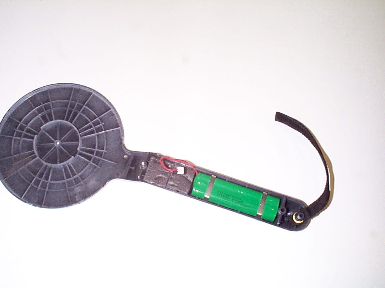
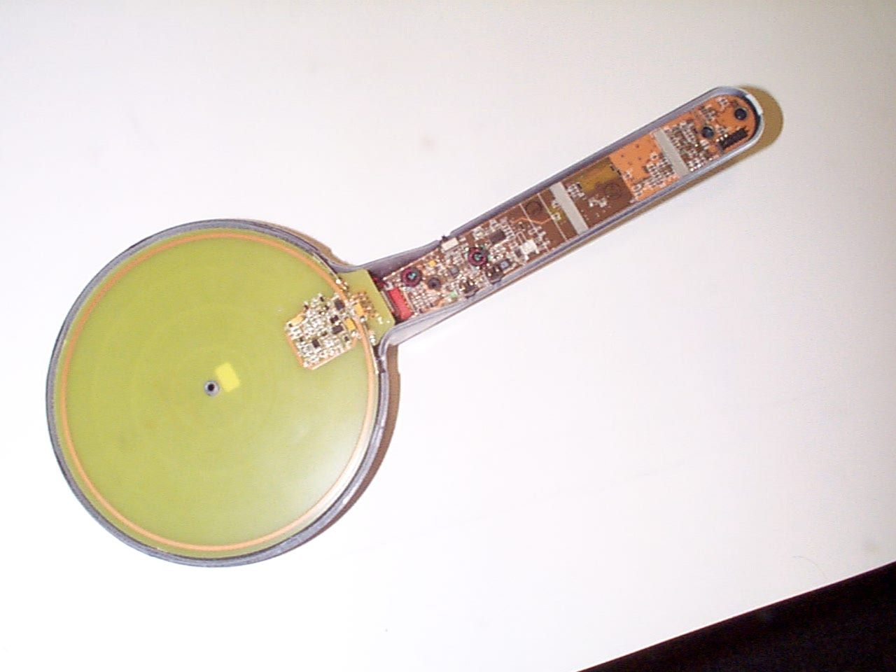
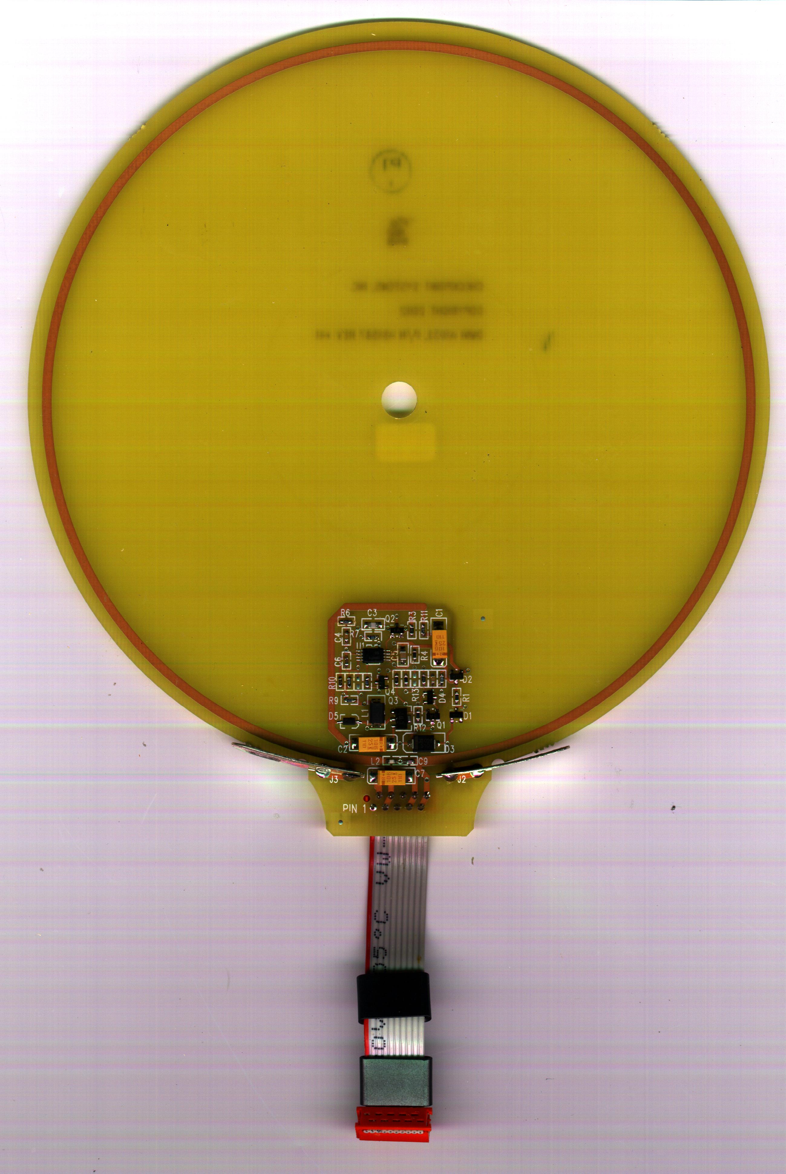
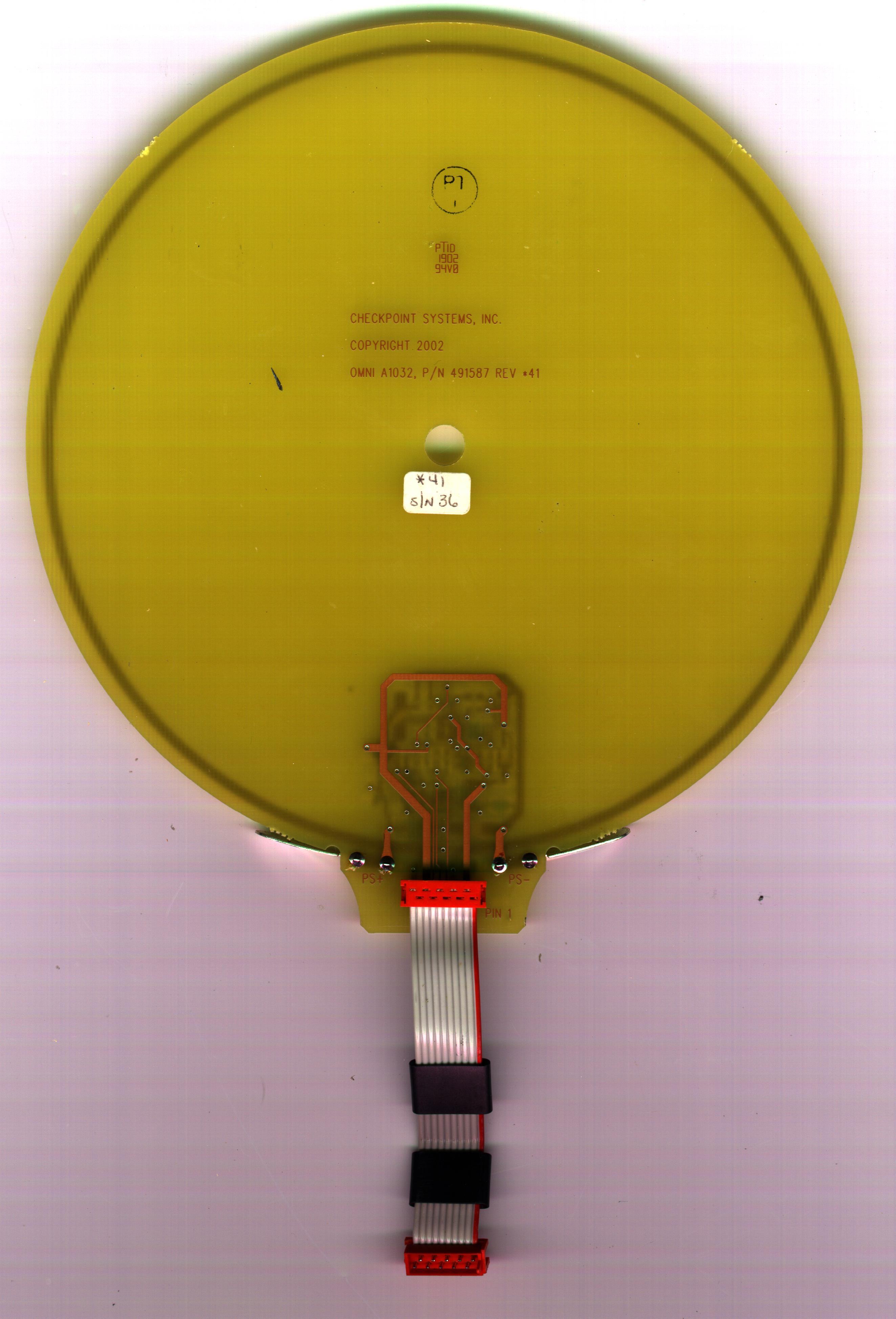
THEORY OF OPERATION, OMNI PORTABLE VERIFIER ____________________________________________________________________________________________________________________________ CHECKPOINT SYSTEMS, INC. CONFIDENTIAL AND PROPRIETARY INFORMATION, FOR INTERNAL USE ONLY. Dwg. No. 7262792 Rev. 02Page 10 Figure 1: Omni Block Diagram Amplitude Control Digital RF Synthesizer Transmitter Power Amplifier ADC Audio LF Amp BPF LED Indicators Detection Algorithm (DSP) LPF Antenna Receiver Charger Battery Pack Regulation I Q 50 MHz Resonator 4 MHz Resonator THEORY OF OPERATION, OMNI PORTABLE VERIFIER ____________________________________________________________________________________________________________________________ CHECKPOINT SYSTEMS, INC. CONFIDENTIAL AND PROPRIETARY INFORMATION, FOR INTERNAL USE ONLY. Dwg. No. 7262792 Rev. 02Page 11 Figure 2: Omni Power Management AC-DC Converter +15V 1.0A Docking Station C/3 Battery Charger 5.0 VDC LDO 3.3 VDC SMPS 1.4 MHz Fixed 2.5 VDC LDO 7.2 VDC 1600 mAh NimH Pack Disable 90-264 VAC 47-63 Hz + 5.0 VDC +3.3 VDC +2.5 VDC +7.2 VDC
Contact Information
Applicant
Nimesh Shah(R&D Director of Operations)
Test Firm
Product Safety Engineering, Inc.Steven Hoke
Technical Specifications
| # | Rule Parts | Frequency Range | Power Output |
|---|---|---|---|
| 9 | 15C | 15.48 MHz - 17.5 MHz | - |
Other Applications from Checkpoint Systems Inc
DO4NS20
Sep 11, 2026EAS RF System
Equipment Class
DXX - Part 15 Low Power Communication Device TransmitterDO4WRTZ1550
Aug 19, 2026UHF-RFID Reader WRTZ-1550
Equipment Class
DSS - Part 15 Spread Spectrum TransmitterDO4EG35
Aug 06, 2026EAS RF Detection System
Equipment Class
DXX - Part 15 Low Power Communication Device TransmitterDO4EP30
Aug 05, 2026EAS RFDetection System
Equipment Class
DXX - Part 15 Low Power Communication Device TransmitterDO4NEO3NP
Mar 23, 2026Antenna Pedestal
Equipment Class
DXX - Part 15 Low Power Communication Device Transmitter