DO4PV20008-2PV2000 Portable Verifier
Checkpoint Systems Inc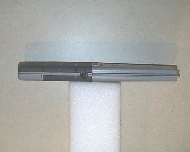
Click to zoom
Application Details
- Equipment Class
- FAP - Part 15 Anti-Pilferage Device
- Date of Grant
- Oct 28, 2001
- Application Purpose
- Original Equipment
- Date of Application
- Aug 16, 2001
- Equipment Note
- PV2000 Portable Verifier
- Frequency Range
- 7.40000000 - 8.80000000
- Company
- Checkpoint Systems Inc
- Country
- United States
Documents & Files
Document Text
Text extracted from the exhibit documents filed with the FCC. Open a document above to read the original.
Users Manual
PV2000 USER’S GUIDE How to use the PV2000 Portable Verifier: • Push and hold the button in. The PV2000 should make three quick beeps to let you know it is working. If the button is released, the PV2000 will turn off. • If it does not beep when turned on the battery may need to be replaced. (See How to replace batteries section) • While maintaining the button depression, slowly sweep the unit four to six inches from the possible location of the tag. An audible tone confirms the presence of the tag. A red light will also flash on the unit. How to replace the batteries: • Remove the single screw on the bottom of the unit, and slide off the plastic shell. • Pull battery from battery compartment and place new one in. • The PV2000 uses a standard 9Volt battery. Description and function of lights during unit activation: • The red light flashes when there is a Checkpoint tag present. • The green light indicates power to the unit when button is pushed in. • The amber light indicates low battery and the battery should be changed at this time. (See How to replace batteries section)
Cover Letter(s)
Page 1 of 6 VOJTZT PCTC Product Compliance Test Center 2476 Swedesford Road, Malvern, PA 19355 October 15, 200120011021CL Federal Communications Commission EQUIPMENT APPROVAL SERVICES P.O Box 358315 Pittsburgh, PA 15251-5315 Subject: Response to Questions/Requests for Information (Ref No. 20848/Conf No EA102058) Dear Mr. Dichoso, In reference to your correspondence (Reference No. 20848) on the Checkpoint Systems, PV2000 (8.2 MHz Version, FCC ID DO4PV20008-2, (731 Confirmation No EA1020581), I have the assembled the following information and responses for your review. For clarity, I have included your text followed by my comments. COMMENT 1: The block diagram and Schematics are unreadable please submit better versions RESPONSE 1: An updated version of the Theory of Operation, which includes the Block Diagram as its last page has been uploaded. It is labeled “NEW THEORY OF OPERATION WITH BLOCK DIAGRAM”. A cleaner copy of the schematics has been uploaded as a standalone PDF document. It is labeled “PV2000 Schematic 754427.pdf”. For added information I have also uploaded a copy of the Checkpoint TEST AND TUNEUP PROCEDURE” for the 8.2 MHz version. With the exception of minor component changes, the schematic and PCB are common for both the 8.2 MHz and 9.5 MHz versions of the product. Component diferences are identified on the schematic. The board is populated, tuned and setup for the appropriate application using the supplied procedure. COMMENT 2: The Test Report contained the schematics. Supply a test report without confidential material. RESPONSE 2: A revised report has been compiled, which has both photos and figures depicting confidential information removed. It has been uploaded and is labeled “PV2000 (8_2 MHz Ver) FCC Report (20010807R1).pdf”, where the report number – shown in parenthesis – is now amended with a suffix “1” showing the revision level of the test report. Page 2 of 6 COMMENT 3: The internal photos cannot be held confidential. Once someone purchases the device, they can make their own photos. RESPONSE 3: We agree that photos of the internal construction and PCB details can be taken once a product has been purchased by an end user or by a competitor. However, it is Checkpoint’s position that they would prefer the internal detail photos of the PCB, submitted to the FCC, be held as confidential and not be available through the FCC’s web site, and are prepared to pay the fee associated with this request. The photos of the PCB show the internal components and the design of the antenna, which Checkpoint maintains, is proprietary. It is felt that if a competitor wishes to reverse engineer the device, they should not be given an unfair advantage by viewing information regarding the design and layout of the product freely at the FCC site. COMMENT 4: Provide larger clear photos of the component side of the PCB boards. RESPONSE 4: Two new photos of the PCB have been uploaded. One shows the full component side (labeled “pcb.jpg”) and the second is a close-up of the of the lower end of the board showing the component placement on the PCB (labeled “pcb component detail.jpg”). COMMENT 5: Provide the Antenna correction chart for antennas used. Electric field measurements must be made. RESPONSE 5: Two antennas were used during the measurement of emissions from the EUT as identified below. The chart of correction factors for the magnetic field antenna is shown below in Figure 1, and a table of the correction factors for the E-Field antenna is shown in below in Figure 2. Frequency RangeType of AntennaManufacturerModel No. < 30 MHzActive Broadband Magnetic Field Loop Antenna Antenna Research Associates, Inc. BBH-500/B ≥ 30 MHz Passive Biconical-Log Periodic Antenna Antenna Research Associates, Inc. LPB-2520 Page 3 of 6 Figure 1 – Correction Factor Chart for the BBH-500/B Broadband Magnetic Field Antenna As can be seen from the chart, at 8.2 MHz, the magnetic field correction factor is approximately -53 dB. A factor of 51.5 dB must then be added to convert the resultant H-Field measurement to an E-Field. The overall correction factor for a final E-Field measurement is then approximately –1.5 dB. Page 4 of 6 Figures 2 & 3 – Tabulated Antenna Factors for the LPB-2520 BB BiLog E-Field Antenna COMMENT 6: Provide a bandwidth plot of the device. RESPONSE 6: A bandwidth plot was recorded using an HP 8566B spectrum analyzer and a small magnetic field loop field probe placed in close proximity to the device. It is attached below and has also been added to the revised test report referenced above. The red trace shows the envelope of the bandwidth and the blue trace shows the active sweep captured during operation of the device. Page 5 of 6 COMMENT 7: The test data indicates that the measured level for the fundamental is the noise floor level. How does the noise floor level be different by 10 dB between this report and that for the 9.5 MHz version? RESPONSE 7: All measurements are performed on our Open Area Test Site. As such, we are sometimes presented with ambients in the vicinity of signals we are attempting to measure. This happens to be the case here. The fundamental for the 8.2 MHz version was partially obscured by an ambient. The fundamental for the 9.5 MHz version happens to be located in a relatively quiet area between ambient signals. We tried several techniques to capture some measurable level from both of the samples, including moving the antenna in to 10 meters as well as to 3 meters, narrowing the bandwidth, etc. In each case we were unable to detect any recordable level above the noise floor or ambient. Since both of these levels had sufficient margin under the limit, it was recorded as such. Page 6 of 6 COMMENT 8: Verify that the device does not hop on discrete frequencies across the frequency band of 7.4 to 9.0 MHz. RESPONSE 8: The PV2000 product differs from the previous Checkpoint Strata line of Anti-Pilferage Devices in that it is not a digital frequency hopper. The PV2000 employs an a…
Text truncated - open the document above for the full version.
Cover Letter(s)
Page 1 of 1 ΥΝΙΣΨΣ PCTC Product Compliance Test Center 2476 Swedesford Road, Malvern, PA 19355 October 26, 200120010813CL Federal Communications Commission EQUIPMENT APPROVAL SERVICES P.O Box 358315 Pittsburgh, PA 15251-5315 Subject: Confidentiality Statement for Checkpoint Systems PV2000 (8.2 MHz Version). Dear Sir/Madam: The Checkpoint Systems, PV2000 (8.2 MHz Version, FCC ID DO4PV20008-2, (frequency band is 7.4 MHz to 8.8 MHz) was tested for EMI compliance for operating according to the FCC Part 15 Sections 15.209 and 15.223 requirements. Based on the compliance results of this test, please register the Checkpoint System PV2000 (8.2 MHz Version), DO4PV20008-2, with the Federal Communications Commission. Please note that Checkpoint requests confidentiality on the block diagram, theory of operation and schematics of the PV2000 (8.2 MHz Ver). Sincerely, Daniel J. Mis Technical Staff Engineer Unisys Corpration (610) 648-3746 E-Mail: [email protected]
External Photos
EXTERNAL CONSTRUCTION PHOTOS CHECKPOINT SYSTEMS, INC. PV2000 (8.2 MHz Ver) FCC ID – DO4PV20008-2 Photo 1 – View of Both Front (left) and Back (right) Halves of Enclosure EXTERNAL CONSTRUCTION PHOTOS CHECKPOINT SYSTEMS, INC. PV2000 (8.2 MHz Ver) FCC ID – DO4PV20008-2 Photo 2 – View of Left Side of Enclosure EXTERNAL CONSTRUCTION PHOTOS CHECKPOINT SYSTEMS, INC. PV2000 (8.2 MHz Ver) FCC ID – DO4PV20008-2 Photo 3 – View of Right Side of Enclosure
Internal Photos
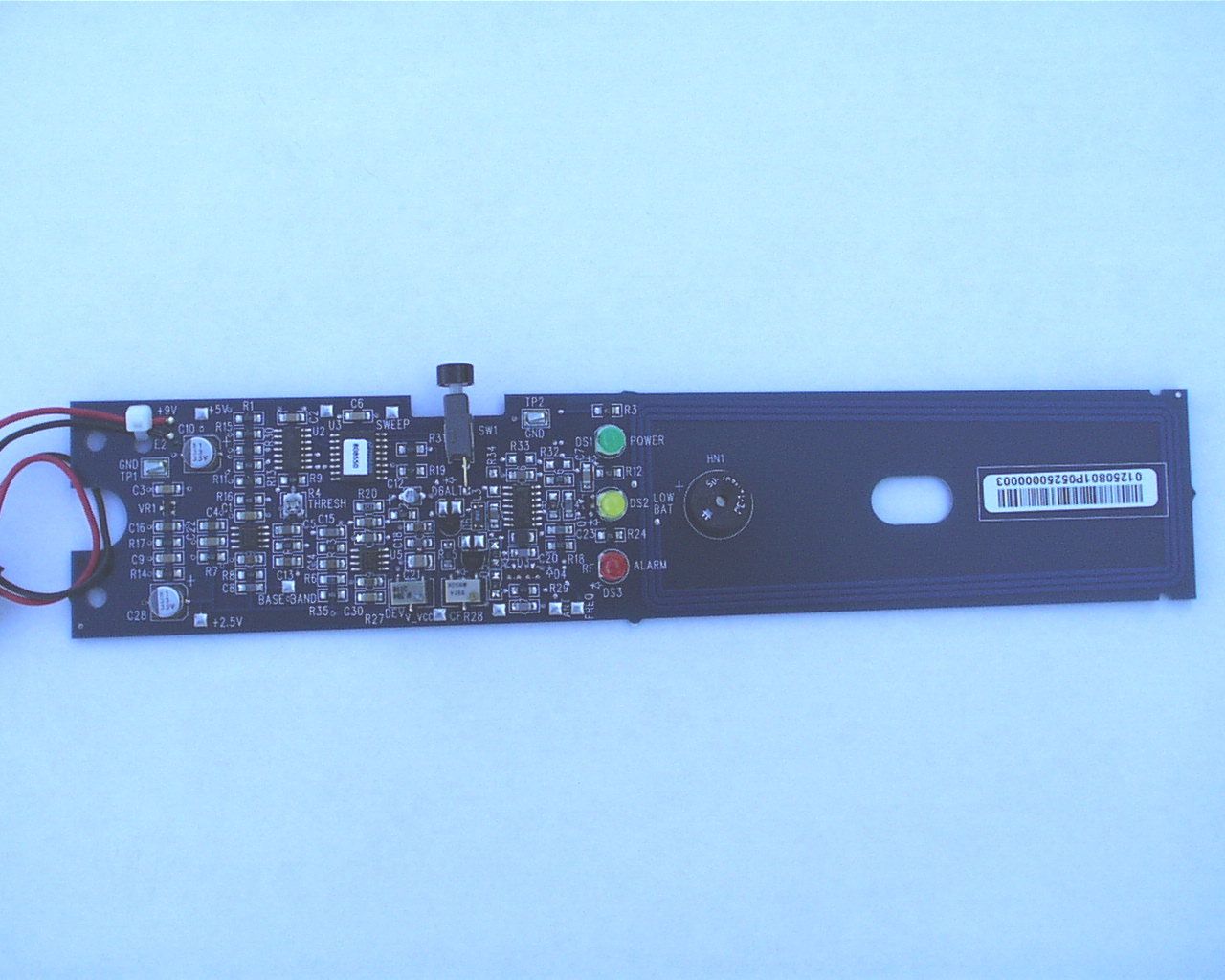
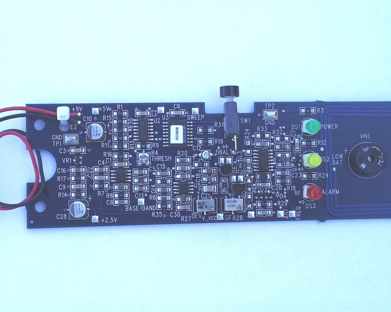
INTERNAL CONSTRUCTION PHOTOS CHECKPOINT SYSTEMS, INC. PV2000 (8.2 MHz Ver) FCC ID – DO4PV20008-2 Photo 1 – Interior View INTERNAL CONSTRUCTION PHOTOS CHECKPOINT SYSTEMS, INC. PV2000 (8.2 MHz Ver) FCC ID – DO4PV20008-2 Photo 2 – Front Side of PCB INTERNAL CONSTRUCTION PHOTOS CHECKPOINT SYSTEMS, INC. PV2000 (8.2 MHz Ver) FCC ID – DO4PV20008-2 Photo 3 – Back Side of PCB
Test Report
VOJTZT PCTC Product Compliance Test Center 2476 Swedesford Road, Malvern, PA 19355 ELECTROMAGNETIC COMPATIBILITY TEST REPORT Doc. 20010807R1/Project 597 FCC ID: D04PV20008-2 TEST STANDARD - USA CFR 47 PART 15 PORTABLE VERIFIER MODEL PV2000 CHECKPOINT SYSTEMS, INC. THOROFARE, NJ Test Date: 1/31/01 Issue: October 15, 2001 Prepared by: Daniel J. Mis Technical Staff Engineer Approved by: Wallace E. Amos Group Manager, PCTC/ICC The results described in this report relate only to the item(s) tested. This document shall not be reproduced except in full without written permission of Unisys - PCTC. AMERICAN ASSOCIATION FOR LABORATORY ACCREDITATION Cert. No.: 1028-01 VOJTZT PCTC Page 2 of 24, Date: 10/15/01 Product Compliance Test CenterDoc. 20010807R1/Project 597 FCC ID: D04PV20008-2 ERRATA This document is revision 1 to document 20010807R and is marked as “PCTC Doc. No. 20010807R1”, dated 10/15/01. This revision is issued to make the following corrections and clarifications: - Photo 2 – Detail of Interior Construction - Photo 3 – Top View of PCB - Photo 4 – Bottom View of PCB Removed Photos from the Report. - Figures 1 & 2 – PCB Fabrication - Figures 3, 4 & 5 – Schematics - Figure 6 – Housing Specification Removed Figures from the Report. -Section 6.2Added Section covering Bandwidth Measurement -All PagesReformatted and renumbered all pages VOJTZT PCTC Page 3 of 24, Date: 10/15/01 Product Compliance Test CenterDoc. 20010807R1/Project 597 FCC ID: D04PV20008-2 PREFACE This report documents product testing conducted to verify compliance of the specified EUT with applicable standards and requirements as identified herein. EUT, test instrument configurations, test procedures and recorded data are generally described or attached in the appendices of this report. The reader is referred to the applicable test standards for detailed procedures. The following table summarizes the test results obtained during this evaluation. SUMMARY The Checkpoint Systems, Portable Verifier Model PV2000, were tested to the standards listed below, and found to have the following characteristics: TESTSTANDARDFREQUENCYRESULT Radiated Emissions - Intentional Radiator FCC, Class B Part 15.223 1.705 to 10 MHzBelow Limit Max. Permissible Radiated Emissions - Unintentional Radiator FCC, Class B Part 15.209 30 MHz – 1.0 GHzBelow Limit Max. Permissible Conducted Emissions – Unintentional Radiator FCC, Class B Part 15.207 450 kHz - 30 MHzBelow Limit Max. Permissible VOJTZT PCTC Page 4 of 24, Date: 10/15/01 Product Compliance Test CenterDoc. 20010807R1/Project 597 FCC ID: D04PV20008-2 TABLE OF CONTENTS 1.0Client Information..................................................................................................................6 1.1Requested Service...............................................................................................................6 1.2Purpose of Test(s) ...............................................................................................................6 2.0Description of The Equipment Under Test (EUT).................................................................6 2.1General Description ............................................................................................................6 2.2Equipment Family Description...........................................................................................8 2.3Equipment Sample..............................................................................................................9 2.3.1Identification ................................................................................................................9 2.3.2Condition of Received Sample ....................................................................................9 3.0Applicable Requirements, Methods And Procedures ............................................................9 3.1USA ....................................................................................................................................9 3.2Basic Test Methods and Procedures .................................................................................10 4.0Deviations or Exclusions from the Requirements and Standards ........................................10 5.0Operation of The EUT During Testing ................................................................................10 5.1Test Environment .............................................................................................................10 5.1.1Climatic Environment ................................................................................................10 5.1.2Electrical Power .........................................................................................................10 5.2Grounding .........................................................................................................................10 5.3Operating Mode ................................................................................................................11 5.4Test Configurations ..........................................................................................................11 5.4.1Support Equipment ....................................................................................................11 5.5EUT Modifications ...........................................................................................................11 6.0Summary Of Test Results ....................................................................................................11 6.1Radiated Emission Test ....................................................................................................11 6.1.1Radiated Emission Test (1/31/2001)..........................................................................11 6.1.2Conducted Emissions Test .........................................................................................15 Appendix 1 - Test Equipment Listings ...................................................…
Text truncated - open the document above for the full version.
Test Setup Photos
TEST SETUP PHOTOS CHECKPOINT SYSTEMS, INC. PV2000 (8.2 MHz Ver) FCC ID – DO4PV20008-2 Photo 1 – Front View of Test Setup TEST SETUP PHOTOS CHECKPOINT SYSTEMS, INC. PV2000 (8.2 MHz Ver) FCC ID – DO4PV20008-2 Photo 2 – Rear View of Test Setup
Contact Information
Applicant
Nimesh Shah(R&D Director of Operations)
Technical Contact
Unisys Corporation - PCTCDaniel J Mis
[email protected]610-648-3746
2476 Swedesford Road · Malvern, Pennsylvania · United States
Non-Technical Contact
Unisys Corporation - PCTCDaniel J Mis
[email protected]610-648-3746
Test Firm
Unisys CorporationJohn Baumeister
Technical Specifications
| # | Rule Parts | Frequency Range | Power Output |
|---|---|---|---|
| 1 | 15C | 7.4 MHz - 8.8 MHz | - |
Other Applications from Checkpoint Systems Inc
DO4NS20
Sep 11, 2026EAS RF System
Equipment Class
DXX - Part 15 Low Power Communication Device TransmitterDO4WRTZ1550
Aug 19, 2026UHF-RFID Reader WRTZ-1550
Equipment Class
DSS - Part 15 Spread Spectrum TransmitterDO4EG35
Aug 06, 2026EAS RF Detection System
Equipment Class
DXX - Part 15 Low Power Communication Device TransmitterDO4EP30
Aug 05, 2026EAS RFDetection System
Equipment Class
DXX - Part 15 Low Power Communication Device TransmitterDO4NEO3NP
Mar 23, 2026Antenna Pedestal
Equipment Class
DXX - Part 15 Low Power Communication Device Transmitter