DO4SGRO7000Performa Switch Plate RFID Proximity Reader
Checkpoint Systems Inc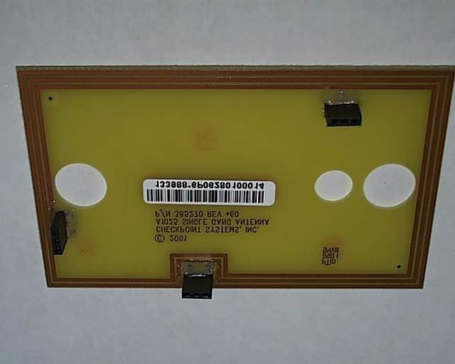
Click to zoom
Application Details
- Equipment Class
- FAP - Part 15 Anti-Pilferage Device
- Date of Grant
- Dec 03, 2001
- Application Purpose
- Original Equipment
- Date of Application
- Oct 14, 2001
- Equipment Note
- Performa Switch Plate RFID Proximity Reader
- Frequency Range
- 13.56000000 - 13.56000000
- Company
- Checkpoint Systems Inc
- Country
- United States
Documents & Files
Document Text
Text extracted from the exhibit documents filed with the FCC. Open a document above to read the original.
Users Manual
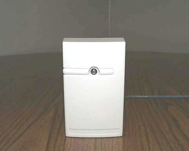
Performa Switch Plate (AC-125S) RFID Proximity Reader Background The following will discuss the Performa Switch Plate reader as they are intended to install on an Access Control System by Checkpoint Systems, Inc. This reader is available in two colors; Gray (Model #AC- 125SG – Part# 882580) and Off-White (Model# AC-125SW – Part# 347151). Specifications The switch plate proximity reader is suitable to mount on metal, such as door mullions, with no impact on performance. This device is designed to use the 26-Bit Weigand data format and is targeted to operate at 12VDC @ 150mA. It is capable of operating between 10.8VDC and 14.8VDC. For these voltages to perform properly, the installation must use Belden 5304FE or equivalent wire. This proximity reader has a read range of up to 4” using the Performa Proximity Plus Cards from Checkpoint. The reader will transmit a frequency of 13.56MHz and will operate between –22°F and 150°F. The Performa reader carries the FCC Part 15 USA certification. Performa Switch Plate Reader Dimensions The following is a drawing of the outer dimensions of this proximity reader. Wiring The Performa readers come with six wires, but currently only five wires will be used. As mentioned above this reader is a Weigand device and uses the 26-Bit Weigand format. The wire specification is Belden 5304FE or equivalent. The wire is 18 gauge, six conductors, stranded, and shielded. With this wire the reader can mount up to 500’ from the controller, as stated within the Weigand specification. The standard color-coding has bee n used: Black Common Re d Power for Reader (12VDC) White Data 1 Green Data 0 Brown LED Control Blue Beeper Control (Not Used At This Time) The following is a diagram of wiring the Performa reader to a Checkpoint Terminal Controller: Dip Switch Settings LED and beeper features are controlled by a dip switch pack located on the back of the reader. The first three positions of the dip switch pack is all that is needed to change the output of the LED and beeper. The fourth dip switch is reserved for future use. The following chart shows the dip switch setting and functionality of the LED and beeper. The LED is bi-color and can provide Red, Green, and Amber states. The beeper is a standard piezo or magnetic beeper. SwitchesNoteLEDBeeper SW 1SW 2SW 3ReadyDeniedAdmitDeniedAdmit ONONONGREENR/G FLASHRED 3s3 SHORTNONE ONONOFFREDR/G FLASHGREEN 3s3 SHORTNONE ONOFFOFFREDR/G FLASH NO CHANGE 3 SHORT1 LONG OFFONONREDR/G FLASHGREEN 3s3 SHORT1 LONG OFFOFFOFF1RED FLICKERSFLICKERS CHIRPSCHIRPS Notes: 1. This is a test mode for the reader. This strictly tests the reader itself and indicates no functionality of the Terminal Controller. JM P 8 Reader 1 Voltage JM P 7 Reader 2 Voltage Jum per 7 and 8 Numbering 3 (top) 2 (center) 1 (bottom ) Bat t ery LED "0" "1" 5V GND 12v 5v Brown White Red Black Green Note: Please refer to your hardware for use of the beeper control and the sixth wire. Checkpoint does not land the beeper control wire to its own board.
Users Manual
Performa Switch Plate (AC-125S) RFID Proximity Reader Background The following will discuss the Performa Switch Plate reader as they are intended to install on an Access Control System by Checkpoint Systems, Inc. This reader is available in two colors; Gray (Model #AC- 125SG – Part# 882580) and Off-White (Model# AC-125SW – Part# 347151). Specifications The switch plate proximity reader is suitable to mount on metal, such as door mullions, with no impact on performance. This device is designed to use the 26-Bit Weigand data format and is targeted to operate at 12VDC @ 150mA. It is capable of operating between 10.8VDC and 14.8VDC. For these voltages to perform properly, the installation must use Belden 5304FE or equivalent wire. This proximity reader has a read range of up to 4” using the Performa Proximity Plus Cards from Checkpoint. The reader will transmit a frequency of 13.56MHz and will operate between –22°F and 150°F. The Performa reader carries the FCC Part 15 USA certification. Performa Switch Plate Reader Dimensions The following is a drawing of the outer dimensions of this proximity reader. Wiring The Performa readers come with six wires, but currently only five wires will be used. As mentioned above this reader is a Weigand device and uses the 26-Bit Weigand format. The wire specification is Belden 5304FE or equivalent. The wire is 18 gauge, six conductors, stranded, and shielded. With this wire the reader can mount up to 500’ from the controller, as stated within the Weigand specification. The standard color-coding has bee n used: Black Common Re d Power for Reader (12VDC) White Data 1 Green Data 0 Brown LED Control Blue Beeper Control (Not Used At This Time) The following is a diagram of wiring the Performa reader to a Checkpoint Terminal Controller: Dip Switch Settings LED and beeper features are controlled by a dip switch pack located on the back of the reader. The first three positions of the dip switch pack is all that is needed to change the output of the LED and beeper. The fourth dip switch is reserved for future use. The following chart shows the dip switch setting and functionality of the LED and beeper. The LED is bi-color and can provide Red, Green, and Amber states. The beeper is a standard piezo or magnetic beeper. SwitchesNoteLEDBeeper SW 1SW 2SW 3ReadyDeniedAdmitDeniedAdmit ONONONGREENR/G FLASHRED 3s3 SHORTNONE ONONOFFREDR/G FLASHGREEN 3s3 SHORTNONE ONOFFOFFREDR/G FLASH NO CHANGE 3 SHORT1 LONG OFFONONREDR/G FLASHGREEN 3s3 SHORT1 LONG OFFOFFOFF1RED FLICKERSFLICKERS CHIRPSCHIRPS Notes: 1. This is a test mode for the reader. This strictly tests the reader itself and indicates no functionality of the Terminal Controller. JM P 8 Reader 1 Voltage JM P 7 Reader 2 Voltage Jum per 7 and 8 Numbering 3 (top) 2 (center) 1 (bottom ) Bat t ery LED "0" "1" 5V GND 12v 5v Brown White Red Black Green Note: Please refer to your hardware for use of the beeper control and the sixth wire. Checkpoint does not land the beeper control wire to its own board.
Cover Letter(s)
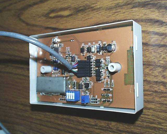
Page 1 of 1 ΥΝΙΣΨΣ PCTC Product Compliance Test Center 2476 Swedesford Road, Malvern, PA 19355 October 15, 200120011001C Federal Communications Commission EQUIPMENT APPROVAL SERVICES P.O Box 358315 Pittsburgh, PA 15251-5315 Subject: Confidentiality Statement for Diamond Checkpoint Performa Switch Plate RFID Proximity Reader (AC-125S) Dear Sir/Madam: The Diamond Checkpoint Performa Switch Plate RFID Proximity Reader (AC-125S), FCC ID D04SGRO7000,(Operating Frequency is 13.56 MHz) was tested for EMI compliance for operating according to the FCC Part 15.209 and 15.225 requirements. Based on the compliance results of this test, please register The Diamond Checkpoint Performa Switch Plate RFID Proximity Reader (AC-125S), FCC ID D04SGRO7000, with the Federal Communications Commission. Please note that Diamond Checkpoint requests confidentiality on the block diagram, theory of operation, schematics, and detail photos of The Diamond Checkpoint Performa Switch Plate RFID Proximity Reader (AC-125S). The detail photographs show the internal components of the Diamond Checkpoint Performa Switch Plate RFID Proximity Reader (AC-125S), design and the manufacturer desires that competitors not have access to them. Sincerely, _____________________ Paul Banker Staff Engineer Unisys - PCTC
Cover Letter(s)
Page 1 of 1 ΥΝΙΣΨΣ PCTC Product Compliance Test Center 2476 Swedesford Road, Malvern, PA 19355 October 15, 200120011001C Federal Communications Commission EQUIPMENT APPROVAL SERVICES P.O Box 358315 Pittsburgh, PA 15251-5315 Subject: Confidentiality Statement for Diamond Checkpoint Performa Switch Plate RFID Proximity Reader (AC-125S) Dear Sir/Madam: The Diamond Checkpoint Performa Switch Plate RFID Proximity Reader (AC-125S), FCC ID D04SGRO7000,(Operating Frequency is 13.56 MHz) was tested for EMI compliance for operating according to the FCC Part 15.209 and 15.225 requirements. Based on the compliance results of this test, please register The Diamond Checkpoint Performa Switch Plate RFID Proximity Reader (AC-125S), FCC ID D04SGRO7000, with the Federal Communications Commission. Please note that Diamond Checkpoint requests confidentiality on the block diagram, theory of operation, schematics, and detail photos of The Diamond Checkpoint Performa Switch Plate RFID Proximity Reader (AC-125S). The detail photographs show the internal components of the Diamond Checkpoint Performa Switch Plate RFID Proximity Reader (AC-125S), design and the manufacturer desires that competitors not have access to them. Sincerely, _____________________ Paul Banker Staff Engineer Unisys - PCTC
External Photos
TECHNICAL DOCUMENTATION October 15, 2001 _______________________________________________________________________________________________________________________________________________ DIAMOND CHECKPOINT DEVELOPMENT GROUP CONFIDENTIAL AND PROPRIETARY INFORMATION, FOR INTERNAL USE ONLY Page 1 Diamond Checkpoint Performa Switch Plate RFID Proximity Reader (AC-125S) FCC ID D04SGRO7000 TECHNICAL DOCUMENTATION October 15, 2001 _______________________________________________________________________________________________________________________________________________ DIAMOND CHECKPOINT DEVELOPMENT GROUP CONFIDENTIAL AND PROPRIETARY INFORMATION, FOR INTERNAL USE ONLY Diamond Checkpoint Performa Switch Plate RFID Proximity Reader (AC-125S) FCC ID D04SGRO7000 Antenna
Test Report
VOJTZT PCTC Product Compliance Test Center 2476 Swedesford Road, Malvern, PA 19355 ELECTROMAGNETIC INTERFERENCE TEST REPORT Doc. 20011001R/Project No. 700 TEST STANDARD - USA CFR 47 PART 15 PERFORMA SWITCH PLATE RFID PROXIMITY READER (AC-125S) FCC ID: DO4SGRO7000 DIAMOND CHECKPOINT DEVELOPMENT GROUP THOROFARE, NJ Test Dates: 5/11/01-10/03/01 Issue: October 1, 2001 Prepared by: Approved by: Paul BankerJohn Baumeister Technical Staff EngineerActing Group Manager PCTC/ICC The results described in this report relate only to the item(s) tested. This document shall not be reproduced except in full without written permission of Unisys - PCTC. AMERICAN ASSOCIATION FOR LABORATORY ACCREDITATION Cert. No.: 1028.1 VOJTZT PCTC Page 2 of 18, 10/1/01 Product Compliance Test CenterDoc. 20011001R/Project No. 700 FCC ID: DO4SGRO7000 PREFACE This report documents product testing conducted to verify compliance of the specified EUT with applicable standards and requirements as identified herein. EUT, test instrument configurations, test procedures and recorded data are generally described or attached in the appendices of this report. The reader is referred to the applicable test standards for detailed procedures. The following table summarizes the test results obtained during this evaluation. SUMMARY The Diamond Checkpoint Inc., Performa Switch Plate RFID Proximity Reader (AC-125S), as described in Section 2.1, was tested to the standards listed below, and found to have the following characteristics: TESTSTANDARDFrequency RangeRESULT Radiated Emissions Intentional Radiator, Harmonics 47 CFR Subpart C, 15.209 9 kHz to 1 GHz Below Max. Permissible Limit Radiated Emissions Intentional Radiator, Fundamental 47 CFR Subpart C, 15.225 13.553 to 13.567 MHz Below Max. Permissible Limit Frequency Stability 47 CFR Subpart C, 15.225 13.56 ±0.01%Within Tolerance VOJTZT PCTC Page 3 of 18, 10/1/01 Product Compliance Test CenterDoc. 20011001R/Project No. 700 FCC ID: DO4SGRO7000 TABLE OF CONTENTS 1.0Client Information..................................................................................................................4 1.1Requested Service...............................................................................................................4 1.2Purpose of Test(s) ...............................................................................................................4 2.0Description of the Equipment Under Test (EUT) ..................................................................4 2.1Equipment Family Description...........................................................................................4 2.1.1General .........................................................................................................................4 2.2Equipment Sample..............................................................................................................5 2.2.1Identification ................................................................................................................5 2.2.2Condition of Received Sample ....................................................................................5 3.0Applicable Requirements, Methods And Procedures ............................................................6 3.1Applicable Requirements ...................................................................................................6 3.1.1USA..............................................................................................................................6 3.2Basic Test Methods and Procedures ...................................................................................6 4.0Deviations or Exclusions from the Requirements and Standards ..........................................6 5.0Operation of the EUT During Testing ...................................................................................6 5.1Test Environment ...............................................................................................................6 5.1.1Climatic Environment ..................................................................................................6 5.1.2Electrical Power ...........................................................................................................7 5.2Grounding ...........................................................................................................................7 5.3Operating Mode ..................................................................................................................7 5.4Test Configurations ............................................................................................................7 5.5EUT Modifications .............................................................................................................9 6.0Summary of Test Results .......................................................................................................9 6.1Emission Tests ....................................................................................................................9 6.1.1Radiated Emission Test (8/9/01)..................................................................................9 6.1.2Fundamental Spectral Plot (8/9/2001) .......................................................................12 6.1.3Frequency Stability Test Results (10/3/01)................................................................13 Appendix 1 – Test Equipment Listing ...........................................................................................14 Appendix 2 – Description Of Test Facility and Procedures ..........................................................16 INDEX OF PHOTOS, FIGURES AND TABLES Photo 1 – Performa Switch Plate RFID Proximity Reader (AC-125S) .......................................... 5 Photo 2 – Performa Switch Plate Radiated Emissions Test Setup - Front.................................... 10 Photo 3 -- Performa Switch Plate Radiated Emissions Test Setu…
Text truncated - open the document above for the full version.
Test Report
VOJTZT PCTC Product Compliance Test Center 2476 Swedesford Road, Malvern, PA 19355 ELECTROMAGNETIC INTERFERENCE TEST REPORT Doc. 20011001R/Project No. 700 TEST STANDARD - USA CFR 47 PART 15 PERFORMA SWITCH PLATE RFID PROXIMITY READER (AC-125S) FCC ID: DO4SGRO7000 DIAMOND CHECKPOINT DEVELOPMENT GROUP THOROFARE, NJ Test Dates: 5/11/01-10/03/01 Issue: October 1, 2001 Prepared by: Approved by: Paul BankerJohn Baumeister Technical Staff EngineerActing Group Manager PCTC/ICC The results described in this report relate only to the item(s) tested. This document shall not be reproduced except in full without written permission of Unisys - PCTC. AMERICAN ASSOCIATION FOR LABORATORY ACCREDITATION Cert. No.: 1028.1 VOJTZT PCTC Page 2 of 18, 10/1/01 Product Compliance Test CenterDoc. 20011001R/Project No. 700 FCC ID: DO4SGRO7000 PREFACE This report documents product testing conducted to verify compliance of the specified EUT with applicable standards and requirements as identified herein. EUT, test instrument configurations, test procedures and recorded data are generally described or attached in the appendices of this report. The reader is referred to the applicable test standards for detailed procedures. The following table summarizes the test results obtained during this evaluation. SUMMARY The Diamond Checkpoint Inc., Performa Switch Plate RFID Proximity Reader (AC-125S), as described in Section 2.1, was tested to the standards listed below, and found to have the following characteristics: TESTSTANDARDFrequency RangeRESULT Radiated Emissions Intentional Radiator, Harmonics 47 CFR Subpart C, 15.209 9 kHz to 1 GHz Below Max. Permissible Limit Radiated Emissions Intentional Radiator, Fundamental 47 CFR Subpart C, 15.225 13.553 to 13.567 MHz Below Max. Permissible Limit Frequency Stability 47 CFR Subpart C, 15.225 13.56 ±0.01%Within Tolerance VOJTZT PCTC Page 3 of 18, 10/1/01 Product Compliance Test CenterDoc. 20011001R/Project No. 700 FCC ID: DO4SGRO7000 TABLE OF CONTENTS 1.0Client Information..................................................................................................................4 1.1Requested Service...............................................................................................................4 1.2Purpose of Test(s) ...............................................................................................................4 2.0Description of the Equipment Under Test (EUT) ..................................................................4 2.1Equipment Family Description...........................................................................................4 2.1.1General .........................................................................................................................4 2.2Equipment Sample..............................................................................................................5 2.2.1Identification ................................................................................................................5 2.2.2Condition of Received Sample ....................................................................................5 3.0Applicable Requirements, Methods And Procedures ............................................................6 3.1Applicable Requirements ...................................................................................................6 3.1.1USA..............................................................................................................................6 3.2Basic Test Methods and Procedures ...................................................................................6 4.0Deviations or Exclusions from the Requirements and Standards ..........................................6 5.0Operation of the EUT During Testing ...................................................................................6 5.1Test Environment ...............................................................................................................6 5.1.1Climatic Environment ..................................................................................................6 5.1.2Electrical Power ...........................................................................................................7 5.2Grounding ...........................................................................................................................7 5.3Operating Mode ..................................................................................................................7 5.4Test Configurations ............................................................................................................7 5.5EUT Modifications .............................................................................................................9 6.0Summary of Test Results .......................................................................................................9 6.1Emission Tests ....................................................................................................................9 6.1.1Radiated Emission Test (8/9/01)..................................................................................9 6.1.2Fundamental Spectral Plot (8/9/2001) .......................................................................12 6.1.3Frequency Stability Test Results (10/3/01)................................................................13 Appendix 1 – Test Equipment Listing ...........................................................................................14 Appendix 2 – Description Of Test Facility and Procedures ..........................................................16 INDEX OF PHOTOS, FIGURES AND TABLES Photo 1 – Performa Switch Plate RFID Proximity Reader (AC-125S) .......................................... 5 Photo 2 – Performa Switch Plate Radiated Emissions Test Setup - Front.................................... 10 Photo 3 -- Performa Switch Plate Radiated Emissions Test Setu…
Text truncated - open the document above for the full version.
Test Setup Photos
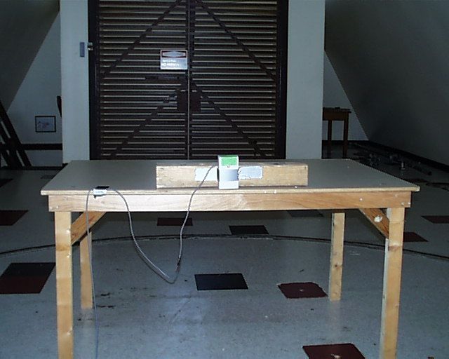
TECHNICAL DOCUMENTATION October 15, 2001 Photo 1 – Photo of Radiated Emission test setup of The Diamond Checkpoint Performa Switch Plate RFID Proximity Reader (AC-125S), FCC ID D04SGRO7000 Front view TECHNICAL DOCUMENTATION October 15, 2001 Photo 2 – Photo of Radiated Emission test setup of The Diamond Checkpoint Performa Switch Plate RFID Proximity Reader (AC-125S), FCC ID D04SGRO7000 Rear view
Contact Information
Applicant
Nimesh Shah(R&D Director of Operations)
Technical Contact
Unisys CorporationPaul M Banker
[email protected]610-648-3723
PCTC Building · Malvern, Pennsylvania · United States
Non-Technical Contact
Unisys Corporation - PCTCPaul M Banker
[email protected]610-648-3723
Test Firm
Unisys CorporationJohn Baumeister
Technical Specifications
| # | Rule Parts | Frequency Range | Power Output |
|---|---|---|---|
| 1 | 15C | 13.56 MHz - 13.56 MHz | - |
Other Applications from Checkpoint Systems Inc
DO4NS20
Sep 11, 2026EAS RF System
Equipment Class
DXX - Part 15 Low Power Communication Device TransmitterDO4WRTZ1550
Aug 19, 2026UHF-RFID Reader WRTZ-1550
Equipment Class
DSS - Part 15 Spread Spectrum TransmitterDO4EG35
Aug 06, 2026EAS RF Detection System
Equipment Class
DXX - Part 15 Low Power Communication Device TransmitterDO4EP30
Aug 05, 2026EAS RFDetection System
Equipment Class
DXX - Part 15 Low Power Communication Device TransmitterDO4NEO3NP
Mar 23, 2026Antenna Pedestal
Equipment Class
DXX - Part 15 Low Power Communication Device Transmitter