DO4STRATAMX
Checkpoint Systems Inc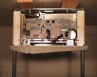
Click to zoom
Application Details
- Equipment Class
- FAP - Part 15 Anti-Pilferage Device
- Date of Grant
- Jun 07, 2000
- Application Purpose
- Original Equipment
- Date of Application
- Apr 19, 2000
- Frequency Range
- 8.44900000 - 8.69900000
- Company
- Checkpoint Systems Inc
- Country
- United States
Documents & Files
Document Text
Text extracted from the exhibit documents filed with the FCC. Open a document above to read the original.
Users Manual
NOTICE TO PERSONS RECEIVING THIS DRAWING AND/OR TECHNICAL INFORM ATION: Title: TUNING PROCEDURE TR4022 Checkp oint Sy st ems claims p rop riet ary right s t o t he mat erial disclosed hereon. This drawing and/or technical information is issued in confidence for engineering information only and may not be rep roduced or used to manufacture any thing shown or referred to hereon without direct written p ermission from Checkp oint Sy stems to the user. This drawing and/or technical information is the p rop erty of Checkp oint Sy st ems and is loaned for mut ual assist ance, t o be ret urned when it s p urp ose has been served. THIS DRAWING AND/OR TECHNICAL INFORMATION IS THE PROPERTY OF CHECKPOINT S YS TEMS , INC. RevisionsRevisions RevDescriptionDateEngineerRevDescriptionDateApproved 01ECN03/28/2000D. MERVA Doc Spec:Date: Dwn: J. IANNUZZIDate: 03/29/2000 Chk: J. HUGDate: 03/29/2000 Eng: D. MERVADate: 03/29/2000 Size A USED ON Appd: E. ECKSTEIND ate : 03/29/2000 Scale: N/A Checkpoint Systems, Inc. 2000 Page 1 of 20 TUNING PROCEDURE TR4022 ____________________________________________________________________________________________________________________________ CHECK PO IN T SYSTEMS, IN C. CO N FIDEN TIAL AN D PRO PRIETARY IN FO RMATIO N , FO R IN TERN AL USE O N LY. Rev. 00Page 2 TABLE OF CONTENTS 1.0 INTRODUCTION ..........................................................................................................3 2.0 SYSTEM DESCRIPTION .............................................................................................3 3.0 SWITCH SETTINGS .....................................................................................................4 4.0 LED DEFINITIONS.....................................................................................................10 5.0 POTENTIOMETER ADJUSTMENT...........................................................................11 6.0 AUXILIARY CONNECTOR .......................................................................................12 7.0 SCREENS ....................................................................................................................13 7.1 Frame Field Display Area ............................................................................................................... 14 8.0 TUNING.......................................................................................................................19 8.1 Jumper Setup .................................................................................................................................. 19 8.2 Group Addressing (VERY IMPORTANT)..................................................................................... 19 8.3 Slaving ............................................................................................................................................ 19 TUNING PROCEDURE TR4022 ____________________________________________________________________________________________________________________________ CHECK PO IN T SYSTEMS, IN C. CO N FIDEN TIAL AN D PRO PRIETARY IN FO RMATIO N , FO R IN TERN AL USE O N LY. Rev. 00Page 3 1.0INTRODUCTION This document describes the procedures required to properly tune a Strata System with the TR4022 board. Many of the adjustments for the Strata are pre-tuned during the manufacturing test process therefore adjustments required in the field have been minimized. Adjustments such as center frequency and sweep are preset for 8.2 Mhz operation. If the system is required to detect a different frequency tag the sweep range will need to be readjusted by the installer. Once properly configured, if poor performance results, the CSE should direct their efforts toward finding the source of the interference in the environment. Several test signals are provided by the TR4022 board, which may be viewed on an oscilloscope. These signals allow the CSE to identify and measure ambient noise levels, resonances and other sources of environmental interference. The DSP (digital signal processor) system automatically subtracts stationary resonances seen by the antennas. The system offers flexibility to adjust for these circumstances. However, the solution for environmental problems, is to determine the environmental problems and resolve them. The options for adjusting to environmental problems are performed both in the analog and digital realm by the technician. The analog solutions are reducing power on the transmit antennas (2-loop and/or 3-loop), reduce the baseband gain, and adjust the sweep. In the digital toolbox there are four user selectable filter parameters. These tools should be used only after the CSE has attempted to correct the environment. The Strata system is powered by a +24Vdc power supply, P/N 121878. This power supply can power up to a maximum of three antennas. 2.0SYSTEM DESCRIPTION The Strata system is a transceiver design using both a 3-loop, 2-loop, and a 1-loop antenna design. The Strata alternates between using the 2-loop antenna and the 3-loop antenna. The 1-loop antenna is used as a shield that is tied to ground. This technique provides the system with different views of the detection field allowing the system to improve detection by minimizing the holes typically found at the crossbars of typical swept antennas. During an antenna’s cycle, the system performs two “blasts” which are called a “bin”. There are sixteen bins per frame. A bin consists of two “noise” cycles and two blast cycles, a blast is a transmit cycle and then a receive cycle. During the noise cycle, the system is not transmitting, only receiving ambient noise. This allows the system to establish the baseline noise level of the environment for later comparison. The system then transmits or “pulses” the field and then receives or “listens” for an echo of a tag signal. This frame is repeated on the other antenna. A tag response need only be present on one of the antennas to cause an alarm. In effect the system provides the best o…
Text truncated - open the document above for the full version.
Attestation Statements
UNISYS PCTC Product Compliance Test Center 2476 Swedesford Road, Malvern, PA 19355 May 25, 2000 FCC Application Processing Branch Correspondence Reference Number: 14198 Applicant: Checkpoint Systems, Inc. 731 Confirmation Number: EA97409 Product: Strata MX FCC ID Number: DO4STRATAMX Gentlemen, Please accept the following responses to the questions posed through E-Mail on the above referenced product. Question 1: The equipment did not list an antenna below 25 MHz. Please list the antenna used. Response 1: Our procedures for performing measurements in the frequency range below 30 MHz for products such as the Strata MX requires the primary use of a magnetic field loop antenna. The measurements documented in the test report submitted for the Strata MX were recorded using a loop antenna manufactured by ARA, Model BBH-500/B, which is capable of calibrated measurements through the frequency range from 300 Hz to 100 MHz. Question 2: Section 15.31(m) requires two frequencies to be tested due to the requested frequencies. Please provide test data at a frequency near the top of the requested frequency band. Response 2: I am interpreting your question/comment to mean that a second measurement is being requested in the 1.704 MHz to 10 MHz band because there appears to be multiple operating fundamental frequencies for the product. Our interpretation of this section was that additional measurements in the 1.704 MHz to 10 MHz band are necessary only when the product under test is capable of being operated at alternative or multiple fundamentals within this band. This product is only capable of operating on the one fundamental, which is defined as being centered on 8.2 MHz and having a 1.2 MHz bandwidth. For this reason only one measurement is presented in the report for the fundamental. It represents the maximum emission level recorded over the 1.2 MHz band of the defined fundamental. It might be helpful to provide a description of the method of operation of the product to help in clarifying our reasoning. The purpose of this product is to detect the presence of Article Surveillance Tags placed on merchandise as a means to deter theft. By its design, the product uses a pulsed, digital hopping, transmitter to detect the presence of an Article Surveillance Tag. These Tags respond by resonating in the 8.2 MHz region when subjected to a pulsed radio transmissions from this product. A Direct Digital Synthesizer (DDS) on the control module, generates a sequence of 16 discrete frequencies from 7.6 MHz to 8.7 MHz (digital sweep). The list of available frequencies are as follows: 7.600708 MHz7.673950 MHz7.747192 MHz7.820435 MHz 7.893677 MHz7.966919 MHz8.040161 MHz8.113403 MHz 8.186646 MHz8.259888 MHz8.333130 MHz8.406372 MHz 8.479614 MHz8.552856 MHz8.626099 MHz8.699341 MHz The restricted bands in this area are: 8.291 - 8.294MHz 8.362 – 8.366 MHz 8.37625 – 8.38675 MHz 8.41425 – 8.41475 MHz Per Section 15.205, the transmitter is not capable of hopping into or operating in, any of the restricted frequency bands. The generation and transmission of these 16 discrete frequencies constitutes the fundamental, which is centered at 8.2 MHz and has a 1.2 MHz bandwidth. A plot of the fundamental can be found in Section 6.1.2 of the submitted report. This plot shows the overall shape of the fundamental and its associated bandwidth. Although there are 16 individual frequencies listed, together they constitute the fundamental operating frequency or frequency band of the device. They are not 16 individual fundamentals. Based on the operation of the device, we interpreted the complete transmission pattern as the fundamental, and measured the worst case accordingly. There are no other intentional radiator emissions present within the 1.704 MHz to 10 MHz band that can be attributed to the operation of this product. 3) I must also respond to your comment regarding the ED GIBBONS correspondance. The products designed and manufactured by Checkpoint Systems have always been of the pulsed, digital hopping, transmitter type. Checkpoint Systems approached the FCC with the intention of clarifying the measurement method to be used for their particular products. The letter from Mr. Gibbons describing the procedure to measure the emissions from their transmitters was a result of conversations between the two parties. So I feel I must disagree with your interpretation. The correspondence was meant to describe a measurement method for their particular pulsed digitally swept frequency system that hops on discrete frequencies. We are also aware of the ban on hopping into the restricted bands. This product incorporates the use of a discrete digital synthesizer to generate the particular frequencies to be used to constitute the fundamental. The specific frequencies used by the transmitter are shown above along with the appropriate restricted bands within the 7.6 MHz to 8.7 MHz region. The transmitter is incapable of hopping into the restricted bands. I hope these responses satisfy your questions. If more information is required, please contact Eric Eckstein ([email protected]) and Nemish Shah ([email protected]) at Checkpoint Systems, Inc. and myself ([email protected]). Regards, Daniel J. Mis Unisys Corpration Product Compliance Test Center 2476 Swedesford Road Malvern, Pennsylvania 19355 Office: (610) 648-3746 Fax:(610) 695-5450 E-Mail: [email protected]
Cover Letter(s)
Page 1 of 1 ΥΝΙΣΨΣ PCTC Product Compliance Test Center 2476 Swedesford Road, Malvern, PA 19355 April 19, 200020000413CL Federal Communications Commission EQUIPMENT APPROVAL SERVICES P.O Box 358315 Pittsburgh, PA 15251-5315 Subject: Confidentiality Statement for Checkpoint Systems Strata MX System. Dear Sir/Madam: The Checkpoint Systems, Strata MX, FCC ID DO4STRATAMX, (frequency band is 7.6MHz to 8.7 MHz) was tested for EMI compliance for operating according to the FCC Part 15 Sections 15.209 and 15.223 requirements. Based on the compliance results of this test, please register the Checkpoint System Strata MX, DO4STRATAMX, with the Federal Communications Commission. Please note that Checkpoint requests confidentiality on the block diagram, theory of operation, schematics, and detail photos of the Strata MX. The detail photographs show the internal components of the Strata MX and antenna design and the manufacturer desires that competitors not have access to them. Sincerely, Daniel J. Mis Technical Staff Engineer Unisys Corpration (610) 648-3746 E-Mail: [email protected]
External Photos
TECHNICAL DOCUMENTATION April 20, 2000 _______________________________________________________________________________________________________________________________________________ CHECKPOINT SYSTEMS, INC. CONFIDENTIAL AND PROPRIETARY INFORMATION, FOR INTERNAL USE ONLY Page 1 External Front view # 1 of STRATA MX FCC ID D04STRATAMX TECHNICAL DOCUMENTATION April 20, 2000 _______________________________________________________________________________________________________________________________________________ CHECKPOINT SYSTEMS, INC. CONFIDENTIAL AND PROPRIETARY INFORMATION, FOR INTERNAL USE ONLY Page 2 External rear view # 2 of STRATA MX FCC ID D04STRATAMX
Test Report
UNISYS PCTC Product Compliance Test Center 2476 Swedesford Road, Malvern, PA 19355 ELECTROMAGNETIC COMPATIBILITY TEST REPORT Doc.20000413R/Project No. 460 TEST STANDARD - USA CFR 47 PART 15 STRATA MX ELECTRONIC ARTICLE SURVEILANCE DETECTION SYSTEM FCC ID: DO4STRATAMX CHECKPOINT SYSTEMS, INC. THOROFARE, NJ Test Date: 1/28/00, 2/2/2000, 3/7/2000 Issue: April 19, 2000 Prepared by: Daniel J. Mis Technical Staff Engineer Approved by: Wallace E. Amos Group Manager, PCTC/ICC The results described in this report relate only to the item(s) tested. This document shall not be reproduced except in full without written permission of Unisys - PCTC. AMERICAN ASSOCIATION FOR LABORATORY ACCREDITATION UNISYS PCTC Page 2 of 35, 4/19/00 Product Compliance Test CenterDoc.20000413R/Project No. 460 FCC ID: DO4STRATA MX PREFACE This report documents product testing conducted to verify compliance of the specified EUT with applicable standards and requirements as identified herein. EUT, test instrument configurations, test procedures and recorded data are generally described or attached in the appendices of this report. The reader is referred to the applicable test standards for detailed procedures. The following table summarizes the test results obtained during this evaluation. SUMMARY The Checkpoint Systems, Inc., Strata MX as described in Section 2.1, was tested to the standards listed below, and found to have the following characteristics: TESTSTANDARDFrequency RangeRESULT Radiated Emissions Intentional Radiator, Fundamental FCC Part 15.223 1.705 to 10 MHz Below Max. Permissible Limit Radiated Emissions Intentional Radiator, Harmonics FCC Part 15.209 10 MHz to 1 GHz Below Max. Permissible Limit Radiated Emissions Unintentional Radiator (Related to Digital Circuitry) FCC Part 15.109 30 MHz to 1 GHz Below Max. Permissible Limit Conducted Emissions Intentional Radiator FCC Part 15.207 450 kHz to 30 MHz Below Max. Permissible Limit UNISYS PCTC Page 3 of 35, 4/19/00 Product Compliance Test CenterDoc.20000413R/Project No. 460 FCC ID: DO4STRATA MX TABLE OF CONTENTS 1.0Client Information.............................................................................................................5 1.1Requested Service..........................................................................................................5 1.2Purpose of Test(s)..........................................................................................................5 2.0Description of The Equipment Under Test (EUT)..............................................................5 2.1Equipment Family Description........................................................................................5 2.1.1General....................................................................................................................5 2.2Equipment Sample..........................................................................................................7 2.2.1Identification............................................................................................................7 2.2.2Condition of Received Sample.................................................................................9 3.0Applicable Requirements, Methods And Procedures..........................................................9 3.1Applicable Requirements................................................................................................9 3.1.1USA........................................................................................................................9 3.2Basic Test Methods and Procedures...............................................................................9 4.0Deviations Or Exclusions From The Requirements And Standards...................................10 5.0Operation Of The EUT During Testing............................................................................10 5.1Test Environment.........................................................................................................10 5.1.1Climatic Environment.............................................................................................10 5.1.2Electrical Power.....................................................................................................10 5.2Grounding....................................................................................................................10 5.3Operating Mode...........................................................................................................11 5.4Test Configurations......................................................................................................12 5.4.1Support Equipment................................................................................................14 5.5EUT Modifications.......................................................................................................14 6.0Summary Of Test Results................................................................................................15 6.1Emission Tests.............................................................................................................15 6.1.1Radiated Emission Test (3/7/2000).........................................................................15 6.1.2Bandwidth Measurement (1/28/2000)....................................................................20 6.1.3Conducted Emission Test (2/2/2000).....................................................................21 Appendix 1 – Test Equipment Listing........................................................................................24 Appendix 2 – Description Of Test Facility and Procedures.........................................................26 Appendix 3 – EUT Drawings....................................................................................................30 Appendix 4 – Correspondence Letter........................................................................................34 UNISYS PCTC Page…
Text truncated - open the document above for the full version.
Test Setup Photos
TECHNICAL DOCUMENTATION April 20, 2000 _______________________________________________________________________________________________________________________________________________ CHECKPOINT SYSTEMS, INC. CONFIDENTIAL AND PROPRIETARY INFORMATION, FOR INTERNAL USE ONLY Page 1 Photo 1 – Photo of Radiated Emission test setup of STRATA MX FCC ID D04STRATAMX Front view TECHNICAL DOCUMENTATION April 20, 2000 _______________________________________________________________________________________________________________________________________________ CHECKPOINT SYSTEMS, INC. CONFIDENTIAL AND PROPRIETARY INFORMATION, FOR INTERNAL USE ONLY Page 2 Photo 2 – Photo of Radiated Emission test setup of STRATA MX FCC ID D04STRATAMX Rear view TECHNICAL DOCUMENTATION April 20, 2000 _______________________________________________________________________________________________________________________________________________ CHECKPOINT SYSTEMS, INC. CONFIDENTIAL AND PROPRIETARY INFORMATION, FOR INTERNAL USE ONLY Page 3 Photo 3 – Photo of Conducted Emission test setup of STRATAMX FCC ID D04STRATAMX
Contact Information
Applicant
Nimesh Shah(R&D Director of Operations)
Technical Contact
Unsys Corporation - PCTCDaniel J Mis
[email protected]610-648-3746
2476 Swedesford Rd · Malvern, Pennsylvania · United States
Non-Technical Contact
Unisys Corporation - PCTCDaniel J Mis
[email protected]610-648-3746
Technical Specifications
| # | Rule Parts | Frequency Range | Power Output | Tolerance |
|---|---|---|---|---|
| 4 | 15C | 8.449 MHz - 8.699 MHz | - | % |
Other Applications from Checkpoint Systems Inc
DO4NS20
Sep 11, 2026EAS RF System
Equipment Class
DXX - Part 15 Low Power Communication Device TransmitterDO4WRTZ1550
Aug 19, 2026UHF-RFID Reader WRTZ-1550
Equipment Class
DSS - Part 15 Spread Spectrum TransmitterDO4EG35
Aug 06, 2026EAS RF Detection System
Equipment Class
DXX - Part 15 Low Power Communication Device TransmitterDO4EP30
Aug 05, 2026EAS RFDetection System
Equipment Class
DXX - Part 15 Low Power Communication Device TransmitterDO4NEO3NP
Mar 23, 2026Antenna Pedestal
Equipment Class
DXX - Part 15 Low Power Communication Device Transmitter