DXLC-IH-9000IP-Set Top Box
Lung Hwa Electronics Co Ltd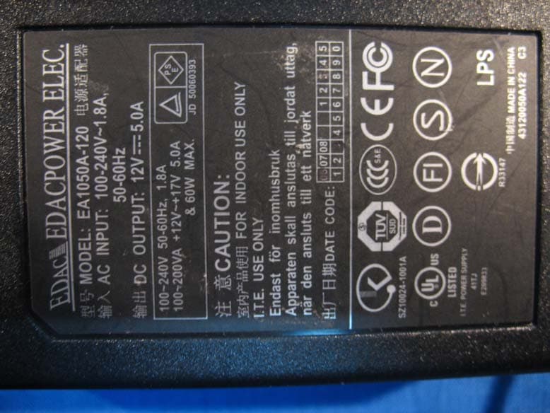
Click to zoom
Application Details
- Equipment Class
- DTS - Digital Transmission System
- Date of Grant
- Feb 26, 2007
- Application Purpose
- Original Equipment
- Date of Application
- Feb 25, 2007
- Equipment Note
- IP-Set Top Box
- Frequency Range
- 2412.00000000 - 2462.00000000
- Company
- Lung Hwa Electronics Co Ltd
- Country
- Taiwan
Documents & Files
Document Text
Text extracted from the exhibit documents filed with the FCC. Open a document above to read the original.
Users Manual
Quick Start Guide Verkorte Handleiding Schnellstarthandbuch Guide de Démarrage Rapide Gravel In Home QRG_all_v0200.ind1 1Gravel In Home QRG_all_v0200.ind1 128-11-2006 13:17:3028-11-2006 13:17:30 2 IN HOME Quick Start Guide 3 Verkorte Handleiding 14 Guide de Démarrage Rapide 25 Schnellstarthandbuch 36 Gravel In Home QRG_all_v0200.ind2 2Gravel In Home QRG_all_v0200.ind2 228-11-2006 13:17:4528-11-2006 13:17:45 3 TABLE OF CONTENTS GUIDELINES FOR SAFE OPERATION Please read the following information carefully before using the In Home. Please keep this manual in a safe place for future reference. Warning Do not use the device with a faulty or third party power supply. A power overload can cause the product to overheat. Do not sharply bend or twist the power ca- bles supplied as this can damage the cable. Do not plug or unplug the battery charger with wet hands or in a moist environment to avoid electric shocks. Use only the adaptor provided with the device or the recommended Commodore replacement. General Remarks Do not attempt to repair or disassemble the device yourself. Do not use corrosive chemicals or detergents to clean the device. Do not use the device near strong magnetic fi elds. Do not drop the device. Do not use the device at temperatures of >40°C or <0°C, or in areas of high humidity. • • • • • • • • • • • • Do not use the device in a dusty or smoky environment. Safe Operation Parental warning: Please ensure that your children use the product with due care. Special Features Software Upgrades: Software upgrades can be downloaded from www.commodoreworld.com ensuring that your In Home remains up to date. Use of accessories and external memory devices USB cable: When copying fi les, ensure that the USB cable is attached until the copy operation has been completed. Insert external memory devices carefully and according to instructions supplied with the device. Environmental Care The device is supplied with a minimum of pack- aging material. Please dispose of packaging materials and electronic products in accordance with local environmental regulations. • • • • • Guidelines For Safe Operation 3 Getting Started 4 Getting To Know Your In Home 5 Using the Remote Control 6 Your In Home Connections 6 Installing The In Home Software 7 Setting In Home Preferences 7 Updating Your In Home 8 Using Your In Home 8 Show What Is Playing Now 9 In Home Music 10 Artists 10 Playlists 11 Friends 11 Local 11 Network 12 Warranty 13 Gravel In Home QRG_all_v0200.ind3 3Gravel In Home QRG_all_v0200.ind3 328-11-2006 13:17:4528-11-2006 13:17:45 4 GETTING STARTED Please read this section carefully to set up your In Home quickly and easily. Your In Home is supplied with the following components. Carefully unwrap the components, and make sure that any plastic bags are disposed of and kept out of children’s reach. PLEASE NOTE If you have a problem, please contact us before returning this product to the supplier. The Commo- doreWorld website provides detailed service information and FAQ’s. General Notice Please fi ll in and return the Product Guaran- tee Card to the designated service center within 30 days of purchase. In case of any diff erences between the device and the manual, please refer to the device. • • • Commodore reserves the right to change technology parameters without prior notifi cation. Commodore reserves the right to revise the manual without prior notifi cation. • • Commodore gravel In Home Remote Control 2x AAA Batteries In Home Power Adapter and Cable Analogue Audio/Video Cable Component to Scart Adapter Quick Start Guide (this booklet) Gravel In Home QRG_all_v0200.ind4 4Gravel In Home QRG_all_v0200.ind4 428-11-2006 13:17:4528-11-2006 13:17:45 5 GETTING TO KNOW YOUR IN HOME The In Home has been designed for use with all types of audio visual media systems, with ports for TV, audio systems and computer networks. If you have a WiFi connection at home, the In Home will detect this and connect you directly to your home network. IMPORTANT NOTICE : PIN CODE You have to register your In Home with CommodoreWorld to receive the Pin Code which is required in the setup phase. Instructions Go to www.commodoreworld.com to register your In Home and receive your Pin Code. You will fi nd the serial number and activation code on the warranty. Please follow the instructions on the warranty card carefully. For a step by step explanation of the setup phase, please read the In Home manual on www.com- modoreworld.com • • • Power On/Off switch DC Power outlet WiFi antenna Coaxial & S/PDIF cable outlet Scart adapter connector port 1. 2. 3. 4. 5. RC Port VGA port HDMI port USB 2.0 slots (2 x) LAN port 6. 7. 8. 9. 10. 67 2 1 8 3 45910 USB 2.0 slot1. 1 Gravel In Home QRG_all_v0200.ind5 5Gravel In Home QRG_all_v0200.ind5 528-11-2006 13:17:5328-11-2006 13:17:53 6 Using the In Home Remote Control The remote control supplied with your In Home is all you need to listen to music, watch fi lms, view photos and manage your In Home. The Remote Control has a unique shuttle control for navigation and selection. First of all, insert the batteries provided in the remote control and pair it with your In Home ( go to the pairing section for detailed information) Inserting the batteries Remove the battery cover Insert the batteries as indicated on the bat- tery cover. Slide the battery cover back into place. Shuttle button • • • 1. Navigation Keys: 2. Forward/Back 3. Left /Right 4. CommodoreWorld™ Instructions Use the keys for on screen navigation. Confi rm your choice by pushing the shuttle button. The CommodoreWorld™ button on the front of the remote control can be used to turn your In Home on and off . Pairing your Remote Control with your In Home You can only access and adjust your In Home functions using the navigation keys and shuttle control on your remote control. You fi rst have to pair the remote control with your In Home. Instructions Press the red button (RC Port) at the rear of the In Home. The In Home front panel LED turns red. …
Text truncated - open the document above for the full version.
External Photos
IP-Set Top Box (M/N: S179L, S179C, S179, S179H) ¾ EUT Photograph – External Photographs (1) EUT Photo (2) EUT Photo (3) EUT Photo (4) EUT Photo (5) EUT Photo (6) EUT Photo (7) EUT Photo (8) EUT Photo
ID Label/Location Info
IP-Set Top Box (M/N: S179L, S179C, S179, S179H) FCC Label Position
Internal Photos
IP-Set Top Box (M/N: S179L, S179C, S179, S179H) ¾ EUT Photograph - Internal Photographs (1) EUT Photo (2) EUT Photo (3) EUT Photo (4) EUT Photo (5) EUT Photo (6) EUT Photo (7) EUT Photo (8) EUT Photo (9) EUT Photo (10) EUT Photo (11) EUT Photo (12) EUT Photo (13) EUT Photo
RF Exposure Info
RF Exposure Evaluation declaration Product Name : IP-Set Top Box Model No. : S179L, S179C, S179, S179H FCC ID : DXLC-IH-9000 Applicant : LUNG HWA Electronices Co .,LTD Address : 3F. 248, Pei Sheng Rd Sec. 3. Sheng Keng Taipei Hsien(222), Taiwan.R.O.C Date of Receipt : 2006/11/10 Issued Date : 2006/12/20 Report No. : 06BS006-RF-US The test results relate only to the samples tested. The test results shown in the test report are traceable to the national/international standard through the calibration of the equipment and evaluated measurement uncertainty herein. This report must not be used to claim product endorsement by CNLA, NVLAP, NIST or any agency of the Government. The test report shall not be reproduced except in full without the written approval of QuieTek Corporation. Report No: 06BS006-RF-US Page: 2 of 4 1. RF Exposure Evaluation 1.1. Limits According to FCC 1.1310: The criteria listed in the following table shall be used to evaluate the environment impact of human exposure to radio frequency (RF) radiation as specified in 1.1307(b) LIMITS FOR MAXIMUM PERMISSIBLE EXPOSURE (MPE) Frequency Range (MHz) Electric Field Strength (V/m) Magnetic Field Strength (A/m) Power Density (mW/cm2) Average Time (Minutes) (A) Limits for Occupational/ Control Exposures 300-1500 -- -- F/300 6 1500-100,000 -- -- 5 6 (B) Limits for General Population/ Uncontrolled Exposures 300-1500 -- -- F/1500 6 1500-100,000 -- -- 1 30 F= Frequency in MHz Friis Formula Friis transmission formula: Pd = (Pout*G)/(4*pi*r2) Where Pd = power density in mW/cm2 Pout = output power to antenna in mW G = gain of antenna in linear scale Pi = 3.1416 R = distance between observation point and center of the radiator in cm Pd id the limit of MPE, 1 mW/cm2 . If we know the maximum gain of the antenna and the total power input to the antenna, through the calculation, we will know the distance r where the MPE limit is reached. 1.2. Test Procedure Software provided by client enabled the EUT to transmit and receive data at lowest, middle and highest channel individually. The temperature and related humidity: 18°Cand 78% RH. Report No: 06BS006-RF-US Page: 3 of 4 1.3. Test Result of RF Exposure Evaluation Product : IP-Set Top Box Test Item : RF Exposure Evaluation Test Site : AC-3 Test Mode : Mode 1: Transmitter by 802.11b Antenna Gain: Antenna Gain: The maximum Gain measured in fully anechoic chamber is 2.0 dBi or 1.58 in linear scale. Output Power Into Antenna & RF Exposure Evaluation Distance: Channel Channel Frequency (MHz) Output Power to Antenna (mW) Power Density at R = 20 cm (mW/cm2) 01 2412.00 31.9154 0.0101 06 2437.00 32.3594 0.0102 11 2462.00 31.6228 0.0100 Note: The power density Pd (4th column) at a distance of 20 cm calculated from the Friis transmission formula is far below the limit of 1 mW/cm2. Report No: 06BS006-RF-US Page: 4 of 4 Product : IP-Set Top Box Test Item : RF Exposure Evaluation Test Site : AC-3 Test Mode : Mode 2: Transmitter by 802.11g Antenna Gain: Antenna Gain: The maximum Gain measured in fully anechoic chamber is 2.0 dBi or 1.58 in linear scale. Output Power Into Antenna & RF Exposure Evaluation Distance: Channel Channel Frequency (MHz) Output Power to Antenna (mW) Power Density at R = 20 cm (mW/cm2) 01 2412.00 9.7724 0.0031 06 2437.00 11.6950 0.0037 11 2462.00 11.1944 0.0035 Note: The power density Pd (4th column) at a distance of 20 cm calculated from the Friis transmission formula is far below the limit of 1 mW/cm2.
Test Report
Test Report Product Name : IP-Set Top Box Model No. : S179L, S179C, S179, S179H FCC ID : DXLC-IH-9000 Applicant : LUNG HWA Electronices Co .,LTD Address : 3F. 248, Pei Sheng Rd Sec. 3. Sheng Keng Taipei Hsien(222), Taiwan.R.O.C Date of Receipt : 2006/11/10 Issued Date : 2006/12/14 Report No. : 06BS006-RF-US-P05V01 The test results relate only to the samples tested. The test results shown in the test report are traceable to the national/international standard through the calibration of the equipment and evaluated measurement uncertainty herein. This report must not be used to claim product endorsement by CNLA, NVLAP, NIST or any agency of the Government. The test report shall not be reproduced except in full without the written approval of QuieTek Corporation. Report No: 06BS006-RF-US-P05V01 Page: 2 of 105 Test Report Certification Issued Date : 2006/12/14 Report No. : 06BS006-RF-US-P05V01 Product Name : IP-Set Top Box Applicant : LUNG HWA Electronices Co .,LTD Address : 3F. 248, Pei Sheng Rd Sec. 3. Sheng Keng Taipei Hsien(222), Taiwan.R.O.C Manufacturer : Expert Electronics (Wujiang)Co.,LTD Model No. : S179L, S179C, S179, S179H FCC ID : DXLC-IH-9000 Rated Voltage : AC 120 V / 60 Hz EUT Voltage : AC 100-240V, 50/60Hz Trade Name : N/A Applicable Standard : FCC CFR Title 47 Part 15 Subpart C: 2006 ANSI C63.4: 2003 Test Result : Complied Performed Location : SuZhou EMC laboratory No.99 Hongye Rd., Suzhou Industrial Park Loufeng Hi-Tech Development Zone., SuZhou, China TEL: +86-512-6251-5088 / FAX:+86-512-6251-5098 Documented By : ( Mandy Liu ) Reviewed By : ( Dream Cao ) Approved By : ( Gene Chang ) Report No: 06BS006-RF-US-P05V01 Page: 3 of 105 Laboratory Information We , QuieTek Corporation, are an independent EMC and safety consultancy that was established the whole facility in our laboratories. The test facility has been accredited by the following accreditation Bodies in compliance with ISO 17025, EN 45001 and Guide 25: The related certificate for our laboratories about the test site and management system can be downloaded from QuieTek Corporation’s Web Site : http://tw.quietek.com/modules/myalbum/ The address and introduction of QuieTek Corporation’s laboratories can be founded in our Web site : http://www.quietek.com/ If you have any comments, Please don’t hesitate to contact us. Our contact information is as below: HsinChu Testing Laboratory : No.75-2, 3rd Lin, Wangye Keng, Yonghxing Tsuen, Qionglin Shiang, Hsinchu County 307, Taiwan, R.O.C. TEL:+886-3-592-8858 / FAX:+886-3-592-8859 E-Mail : [email protected] LinKou Testing Laboratory : No. 5-22, Ruei-Shu Valley, Ruei-Ping Tsuen, Lin-Kou Shiang, Taipei, Taiwan, R.O.C. TEL : 886-2-8601-3788 / FAX : 886-2-8601-3789 E-Mail : [email protected] Suzhou Testing Laboratory : No.99 Hongye Rd., Suzhou Industrial Park Loufeng Hi-Tech Development Zone., SuZhou, China TEL : +86-512-6251-5088 / FAX : 86-512-6251-5098 E-Mail : [email protected] Taiwan R.O.C. : BSMI, DGT, CNLA Germany : TUV Rheinland Norway : Nemko, DNV USA : FCC, NVLAP Japan : VCCI 0914 1313 1596 Report No: 06BS006-RF-US-P05V01 Page: 4 of 105 TABLE OF CONTENTS Description Page 1. General Information .................................................................................................... 6 1.1. EUT Description ........................................................................................... 6 1.2. Model Difference Description........................................................................ 8 1.3. Mode of Operation........................................................................................ 9 1.4. Tested System Details ................................................................................ 10 1.5. Configuration of Tested System.................................................................. 11 1.6. EUT Exercise Software............................................................................... 12 2. Technical Test ........................................................................................................... 13 2.1. Summary of Test Result.............................................................................. 13 2.2. Test Environment........................................................................................ 14 3. Conducted Emission................................................................................................. 15 3.1. Test Equipment........................................................................................... 15 3.2. Test Setup .................................................................................................. 15 3.3. Limit............................................................................................................ 16 3.4. Test Procedure ........................................................................................... 16 3.5. Uncertainty ................................................................................................. 16 3.6. Test Result.................................................................................................. 17 3.7. Test Photograph ......................................................................................... 29 4. Radiated Emission .................................................................................................... 31 4.1. Test Equipment........................................................................................... 31 4.2. Test Setup .................................................................................................. 31 4.3. Limit............................................................................................................ 32 4.4. Test Procedure ........................................................................................... 33 4.5. Uncertainty ................................................................................................. 33 4.6. Test Result..............................................…
Text truncated - open the document above for the full version.
Test Setup Photos
IP-Set Top Box (M/N: S179L, S179C, S179, S179H) Test Mode: Mode 1: Transmit by 802.11b Description: Front View of Conduction Test Test Mode: Mode 1: Transmit by 802.11b Description: Back View of Conduction Test Test Mode: Mode 2: Transmit by 802.11g Description: Front View of Conduction Test Test Mode: Mode 2: Transmit by 802.11g Description: Back View of Conduction Test Test Mode: Mode 1: Transmit by 802.11b Description: Front View of Radiated Test for Under 1GHz Test Mode: Mode 1: Transmit by 802.11b Description: Back View of Radiated Test for Under 1GHz Test Mode: Mode 1: Transmit by 802.11b Description: Front View of Radiated Test for Above 1GHz Test Mode: Mode 1: Transmit by 802.11b Description: Back View of Radiated Test for Above 1GHz Test Mode: Mode 2: Transmit by 802.11g Description: Front View of Radiated Test for Under 1GHz Test Mode: Mode 2: Transmit by 802.11g Description: Back View of Radiated Test for Under 1GHz Test Mode: Mode 2: Transmit by 802.11g Description: Front View of Radiated Test for Above 1GHz Test Mode: Mode 2: Transmit by 802.11g Description: Back View of Radiated Test for Above 1GHz ¾
Contact Information
Applicant
Peter Pai
Technical Contact
Quietek Technology (Suzhou) Co., Ltd.Vincent Lin
Fl.2, No.345, Xin-hu 2nd Rd. · Taipei · Taiwan
Test Firm
DEKRA Testing and Certification (Suzhou) Co., Ltd.Jerry Pan
Technical Specifications
| # | Rule Parts | Frequency Range | Power Output |
|---|---|---|---|
| 1 | 15C | 2.41 GHz - 2.46 GHz | 33.00 mW |
Other Applications from Lung Hwa Electronics Co Ltd
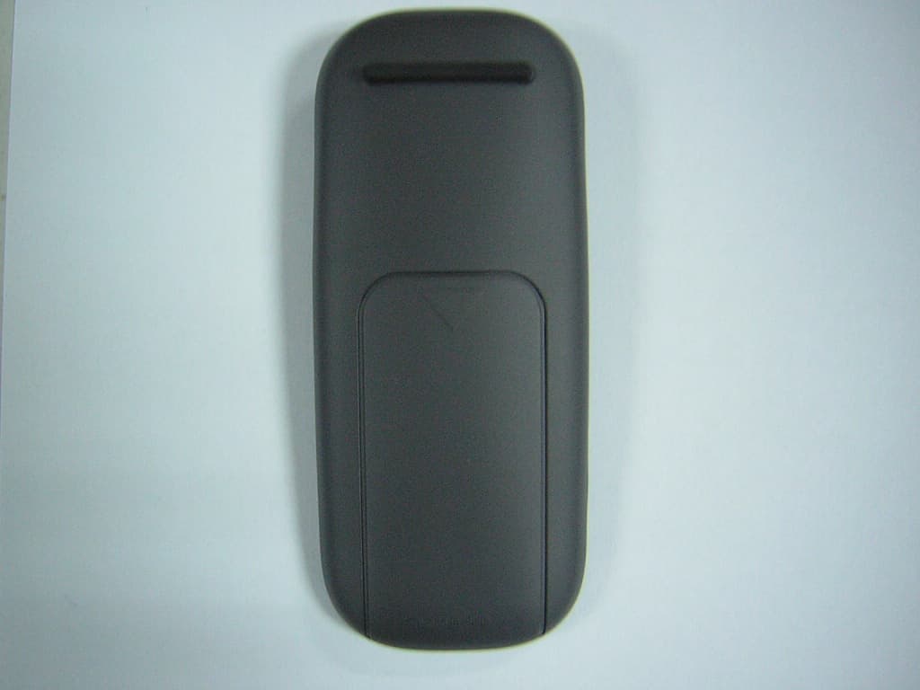
DXLC-IH-90001
Jan 30, 2007RF Remote Control
Equipment Class
DSC - Part 15 Security/Remote Control TransmitterDXLCM17A
May 29, 1997JBP - Part 15 Class B Computing Device Peripheral
Equipment Class
JBP - Part 15 Class B Computing Device PeripheralDXLDP18
Jan 02, 1997JBP - Part 15 Class B Computing Device Peripheral
Equipment Class
JBP - Part 15 Class B Computing Device PeripheralDXLSW101
Dec 09, 1996JBP - Part 15 Class B Computing Device Peripheral
Equipment Class
JBP - Part 15 Class B Computing Device PeripheralDXLCM311
Sep 08, 1996JBP - Part 15 Class B Computing Device Peripheral
Equipment Class
JBP - Part 15 Class B Computing Device Peripheral