E2K24BNHMIntel PRO/Wireless 2200BG WLAN
Dell Inc.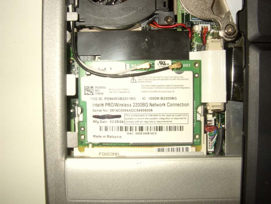
Click to zoom
Application Details
- Equipment Class
- DTS - Digital Transmission System
- Date of Grant
- Apr 26, 2005
- Application Purpose
- Original Equipment
- Date of Application
- Apr 26, 2005
- Equipment Note
- Intel PRO/Wireless 2200BG WLAN
- Frequency Range
- 2412.00000000 - 2462.00000000
- Company
- Dell Inc.
- Country
- United States
Documents & Files
Document Text
Text extracted from the exhibit documents filed with the FCC. Open a document above to read the original.
Users Manual
Dell™ User's Guide Notes, Notices, and Cautions Abbreviations and Acronyms For a complete list of abbreviations and acronyms, see the Glossary. If you purchased a Dell™ n Series computer, any references in this document to Microsoft® Windows® operating systems are not applicable. Information in this document is subject to change without notice. © 2003 Dell Inc. All rights reserved. Reproduction in any manner whatsoever without the written permission of Dell Inc. is strictly forbidden. Trademarks used in this text: Dell, the DELL logo, Latitude,Dell Precision,OptiPlex,Inspiron,Dimension,Dell TravelLite, and DellNet are trademarks of Dell Inc.; Intel and Pentium are registered trademarks and Intel SpeedStep and Centrino are trademarks of Intel Corporation; Microsoft,Windows, Windows NT, and MS-DOS are registered trademarks of Microsoft Corporation; Bluetooth is a trademark owned by Bluetooth SIG, Inc. and is used by Dell Inc. under license; ENERGY STAR is a registered trademark of the U.S. Environmental Protection Agency. As an ENERGY STAR Partner, Dell Inc. has determined that this product meets the ENERGY STAR guidelines for energy efficiency. Other trademarks and trade names may be used in this document to refer to either the entities claiming the marks and names or their products. Dell Inc. disclaims any proprietary interest in trademarks and trade names other than its own. Model PP10L September 2003 P/N M1794 Rev. A00 NOTE:A NOTE indicates important information that helps you make better use of your computer. NOTICE:A NOTICE indicates either potential damage to hardware or loss of data and tells you how to avoid the problem. CAUTION: A CAUTION indicates a potential for property damage, personal injury, or death. Page 1 of 1tp.htm 1/13/2004file://C:\Documents%20and%20Settings\msclark1\Local%20Settings\Temp\~hh985E.htm Glossary A B C D E F G H I K L M N O P R S T U V W X Z Terms in this Glossary are provided for informational purposes only and may or may not describe features included with your particular computer. A AC — alternating current — The form of electricity that powers your computer when you plug the AC adapter power cable in to an electrical outlet. ACPI — advanced configuration and power interface — A power management specification that enables Microsoft® Windows® operating systems to put a computer in standby or hibernate mode to conserve the amount of electrical power allocated to each device attached to the computer. AGP — accelerated graphics port — A dedicated graphics port that allows system memory to be used for video-related tasks. AGP delivers a smooth, true-color video image because of the faster interface between the video circuitry and the computer memory. antivirus software — A program designed to identify, quarantine, and/or delete viruses from your computer. APR — advanced port replicator — A docking device that allows you to conveniently use a monitor, keyboard, mouse, and other devices with your portable computer. ASF — alert standards format — A standard to define a mechanism for reporting hardware and software alerts to a management console. ASF is designed to be platform- and operating system-independent. B backup — A copy of a program or data file on a floppy disk, CD, or hard drive. As a precaution, back up the data files from your hard drive regularly. battery — An internal power source used to operate portable computers when not connected to an AC adapter and an electrical outlet. battery life span — The length of time (years) during which a portable computer battery is able to be depleted and recharged. battery operating time — The length of time (minutes or hours) that a portable computer battery holds a charge while powering the computer. BIOS — basic input/output system — A program (or utility) that serves as an interface between the computer hardware and the operating system. Unless you understand what effect the settings have on the computer, do not change the settings for this program. Also referred to as the system setup program. bit — The smallest unit of data interpreted by your computer. Page 1 of 14Glossary 1/13/2004file://C:\Documents%20and%20Settings\msclark1\Local%20Settings\Temp\~hhBAF1.htm Bluetooth™ — A wireless technology standard for short-range (9 m [29 feet]) networking devices that allows for enabled devices to automatically recognize each other. boot sequence — Specifies the order of the devices from which the computer attempts to boot. bootable CD — A CD that you can use to start your computer. In case your hard drive is damaged or your computer has a virus, ensure that you always have a bootable CD or floppy disk available. Your Drivers and Utilities or Resource CD is a bootable CD. bootable disk — A disk that you can use to start your computer. In case your hard drive is damaged or your computer has a virus, ensure that you always have a bootable CD or floppy disk available. bps — bits per second — The standard unit for measuring data transmission speed. BTU — British thermal unit — A measurement of heat output. bus — A communication pathway between the components in your computer. bus speed — The speed, given in MHz, that indicates how fast a bus can transfer information. byte — The basic data unit used by your computer. A byte is usually equal to 8 bits. C C — Celsius — A temperature measurement system where 0° is the freezing point and 100° is the boiling point of water. cache — A special high-speed storage mechanism which can be either a reserved section of main memory or an independent high-speed storage device. The cache enhances the efficiency of many microprocessor operations. L1 cache — Primary cache stored inside the microprocessor. L2 cache — Secondary cache which can either be external to the microprocessor or incorporated into the microprocessor architecture. carnet — An international customs document that facilitates temporary imports into foreign countries. Also known as a merchandise passport. CD — compact di…
Text truncated - open the document above for the full version.
Users Manual
Intel(R) PRO/Wireless 2200BG User's Guide Your Intel(R) PRO/Wireless 2200BG Network Connection adapter works with either 802.11b or 802.11g wireless standard. Operating at 2.4 GHz frequency at speeds of up to 54 Mbps you can now connect your computer to high-capacity existing 802.11b networks using multiple access points within large or small environments, and also to high-speed 802.11g networks. Your wireless adapter maintains automatic data rate control according to access point location to achieve the fastest possible connection. All your wireless client connections can be easily managed by the Intel(R) PROSet for Wireless utility. Using the Intel(R) PROSet for Wireless Profile Wizard, you can create profiles automatically to suite your specific connection requirements. Enhanced security measures using 802.1x, WPA encryption and authentication, and 128-bit WEP encryption is standard for both 802.11b and 802.11g. Introduction to Wireless Networking Software Installation Using Intel(R) PROSet for Wireless Connecting to a Network Security Overview Setting up Connection Security Troubleshooting Specifications Glossary Customer Support Safety and Regulatory Notices Warranty Adapter Registration Information in this document is subject to change without notice. (c) 2000–2003 Intel Corporation. All rights reserved. Intel Corporation, 5200 N.E. Elam Young Parkway, Hillsboro, OR 97124-6497 USA The copying or reproducing of any material in this document in any manner whatsoever without the written permission of Intel Corporation is strictly forbidden. Intel(R) is a trademark or registered trademark of Intel Corporation or its subsidiaries in the United States and other countries. Other trademarks and trade names may be used in this document to refer to either the entities claiming the marks and names or their products. Intel disclaims any proprietary interest in trademarks and trade names other than its own. Microsoft and Windows are registered trademarks of Microsoft Corporation. *Other names and brands may be claimed as the property of others. Intel Corporation assumes no responsibility for errors or omissions in this document. Nor does Intel make any commitment to update the information contained herein. September 2003 Back to Contents Page Wireless LAN Overview: Intel(R) PRO/Wireless 2200BG User's Guide About Wireless LAN Technology l Choosing a WLAN l Configuring a WLAN l Identifying a WLAN l Surveying the Site of Your WLAN l Factors Affecting Range A wireless network connects computers without using network cables. Computers use radio communications to send data between each other. You can communicate directly with other wireless computers, or connect to an existing network through a wireless access point. When you set up your wireless adapter, you select the operating mode for the kind of wireless network you want. You can use your wireless adapter to connect to other similar wireless devices that comply with the 802.11 standard for wireless networking. Choosing a Wireless LAN Wireless LANs can operate with or without access points, depending on the number of users in the network. Infrastructure mode uses access points to allow wireless computers to send and receive information. Wireless computers transmit to the access point, the access point receives the information and rebroadcasts it to other computers. The access point can also connect to a wired network or to the Internet. Multiple access points can work together to provide coverage over a wide area. Peer-to-Peer mode, also called Ad Hoc mode, works without access points and allows wireless computers to send information directly to other wireless computers. Ad Hoc Mode is only supported in 802.11b and 802.11g networks. You can use Peer-to-Peer mode to network computers in a home or small office or to set up a temporary wireless network for a meeting. Configuring a Wireless LAN There are three basic components that must be configured for an 802.11 wireless LAN to operate properly: l Network Name: Each wireless network uses a unique Network Name to identify the network. This name is called the Service Set Identifier (SSID). When you set up your wireless adapter, you specify the SSID. If you want to connect to an existing network, you must use the name for that network. If you are setting up your own network you can make up your own name and use it on each computer. The name can be up to 32 characters long and contain letters and numbers. l Profiles: When you set up your computer to access a wireless network, the wireless client manager creates a profile for the wireless settings that you specify. If you want to connect to another network, you can scan for existing networks and make a temporary connection, or create a new profile for that network. After you create profiles, your computer will automatically connect when you change locations. l Security: The 802.11 wireless networks use encryption to help protect your data. Wired equivalent privacy (WEP) uses a 64-bit or 128-bit shared encryption key to scramble data. Before a computer transmits data, it scrambles the data using the secret encryption key. The receiving computer uses this same key to unscramble the data. If you are connecting to an existing network, use the encryption key provided by the administrator of the wireless network. If you are setting up your own network you can make up your own key and use it on each computer. m Wi-Fi Protected Access (WPA) is a security enhancement that strongly increases the level of data protection and access control to a WLAN. WPA mode enforces 802.1x authentication and key-exchange to strengthen data encryption. WPA utilizes its Temporal Key Integrity Protocol (TKIP). TKIP provides important data encryption enhancements that include a per-packet key mixing function, a message integrity check (MIC) named "Michael", an extended initialization vector (IV) with sequencing rules, and a also re-keying mechanism. Using these improvement enhanceme…
Text truncated - open the document above for the full version.
Cover Letter(s)
AEGIS LABS, INC 22431 Antonio Parkway B160-417, Rancho Santa Margarita, CA 92688 949-459-7886 TEL 949-459-7869 FAX www.aegislabsinc.com TRANSMITTER MODULAR APPROVAL ATTESTATION April 26, 2005 Federal Communications Commission Re: Application Limited Modular Approval Certification for FCC ID: E2K24BNHM Gentlemen: The following attestation addresses the eight requirements to support modular approval as required by the FCC Public Notice DA00-1407 “Part 15 Unlicensed Modular Transmitter Approval” 1 The modular transmitter has its own RF shielding and does not rely upon the shielding provided by the Dell notebook computer (Model: PP11L) into which it is installed in order to comply with Part 15 limits. 2 The modular transmitter has buffered modulation/data inputs. All inputs to the modules are buffered through the radio circuitry. 3 The modular transmitter has its own power supply regulator. 4 The modular transmitter has an antenna that complies with section 15.203 and 15.204(c) of the FCC rules. It has a UFL type of connector at the transmitter end and is soldered to the antenna. Also the antenna will be internal in the Dell notebook computer (Model: PP11L) and inaccessible to the user. The module is being approved with Foxconn (model: HFT17-DL04) and Hitachi (Model: WDAN- DQJM5001) antennas. 5 The modular transmitter is being approved as a Limited Modular Approval; therefore it was installed in the mini PCI slot of the Dell notebook computer (Model: PP11L). The notebook computer complies with the AC line conducted requirements of Section 15.207. 6 The modular transmitter will be labeled with its own FCC ID. Also, the end user will be informed to display a label referring to the enclosed module. The exterior label will read as follows: “Contains Transmitter Module FCC ID: E2K24BNHM” or “Contains FCC ID: E2K24BNHM”. 7 The modular transmitter is manufactured so that the user cannot influence the operation of the transmitter that will operate outside of the scope of the regulations. Also, a bios lock ensures that the modules will only function in the Dell notebook computer (Model: PP11L) and any other systems that have been FCC approved or are in the review stage of the approval process through a Class II Permissive Change. Also, it ensures that module will not function in any non-Dell or non-FCC- approved Dell system. 8 The modular transmitter meets the MPE calculations of 47 CFR 1.1307(b)(1) for this Dell notebook computer (Model: PP11L). Also, SAR data is available if necessary. If there are any additional questions or if further information is needed, please contact us at your earliest convenience at (949) 459-7886. Sincerely, Rick Candelas Aegis Labs, Inc. Lab Manager
Cover Letter(s)
April 27, 2005 Federal Communications Commission 7435 Oakland Mills Road Columbia, Maryland 21046 Gentlemen: The attached documentation is provided in support of a formal submission to your organization for a “Limited Modular Approval” of an intentional unlicensed transmitter. On behalf of our client, Aegis Labs has included an application for a Grant of Equipment Authorization pursuant to Subpart C of part 15 of FCC Rules (47 CFR) regarding intentional radiators. The data within the test report demonstrates the equipment was tested in a manner described under Part 2 and 15 of the Code of Federal Regulations. This approval is for a “Limited Modular Approval” of the Intel PRO/Wireless 2200BG Network Connection (MN: WM3B2200BG, FCC ID: E2K24BNHM), which is a WLAN adapter (802.11b and 802.11g). It was tested installed in the Mini PCI slot of the Dell notebook computer Latitude | D610 (MN: PP11L) with a set of Hitachi and Foxconn multi- band antennas continuously transmitting and receiving form the MAIN and AUX antenna ports. For this submittal the INTEL PRO/Wireless 2200BG Network Connection is considered the EUT (Equipment Under Test) with the Dell notebook computer (MN: PP11L) its host. If there are any additional questions or if further information is needed, please contact us at your earliest convenience. Sincerely, Rick Candelas Aegis Labs, Inc. Lab Manager Enclosure (1 Emissions Test Report + Exhibits) AEGIS LABS, INC 22431 Antonio Parkway B160-417, Rancho Santa Margarita, CA 92688 949-459-7886 TEL 949-459-7869 FAX www.aegislabsinc.com
Cover Letter(s)
Wireless Driver Platform Lockout Proposal Comms Wireless Development Engineering Version 0.1 04-02-2004 Note: Please refer to http://cec.us.dell.com to see if a newer version exists Table of Contents Table of Contents................................................................................................................ 2 Document Revision History................................................................................................ 3 1.0 Purpose.......................................................................................................................... 4 2.0 Implementation............................................................................................................. 4 3.0 References..................................................................................................................... 4 Document Revision History Version Date Description Name 0.1 04-02-2004 Initial Draft Benjamin Kelley 1.0 Purpose The purpose of this document is to outline an implementation that prevents a wireless driver from installing on predetermined platforms. 2.0 Implementation Wireless NDIS 5.1/5.0 drivers and associated applications will be blocked from installing on predetermined systems based on a system PCI Device ID or Regulatory ID. The system Device ID and Regulatory ID are stored in the SMBIOS table. Because the SMBIOS information can not be read directly from Windows and not all information elements are exposed via WMI, Dell will provide a 16-bit DOS application that will query the appropriate SMBIOS tables and map the information into the Windows registry at HKEY_LOCAL_MACHINE\SOFTWARE\Dell Computer Corporation\SysInfo The vendor is responsible for architecting their Install Shield (MSI) package such that sysinfo.exe is executed (e.g. “launchappandwait()”) to generate the appropriate SMBIOS information in the registry. The Install Shield package is then required to query the following keys: If “System Manufactuer” does not contain the string “Dell” Then fail (“Installation not supported on non Dell platforms.”) Else if “SystemId” is not found in SystemId map OR “RegulatoryID” is not found in RegulatoryID map Then fail (“Installation not supported on this platform.”) The Install shield package is responsible for checking the SystemId and RegulatoryID against values stored in a separate file (e.g. .ini). The vendor is responsible for providing basic encryption/decryption tools that allow Dell to scramble the SystemID/RegulatoryID lists into the .ini file. This allows Dell to add support for new systems to existing Installer packages, and prevents the driver lock from being circumvented. 3.0 References Dellinfo.zip (pw = “dell”)
Cover Letter(s)
www.dell.com | support.dell.com Installing and Configuring the Mini PCI Card5 Installing and Configuring the Mini PCI Card CAUTION: Before performing any of the procedures listed below, read and follow the safety instructions in the System Information Guide or the Owner's Manual that came with your computer. Read the information on the following pages before you complete the setup of your wireless network. Before You Begin Ensure that you have the following items: •Your portable computer •Your Mini PCI card •The CD that came with your wireless Mini PCI card •The Dell™ TrueMobile™ 1180/1300/1400 Wireless Mini PCI Card and Intel ® Pro/Wireless LAN 3A Mini PCI Adapter Setup Guide •The regulatory label(s) if required in your region For Latitude™ D600/D500 and Inspiron™ 600m/500m Computers Installing the Mini PCI Card 1Ensure that the work surface is flat and clean to prevent the computer cover from being scratched. 2Save and close any open files, exit any open programs, and then shut down the computer. www.dell.com | support.dell.com 6Installing and Configuring the Mini PCI Card 3If the computer is connected to a docking device (docked), undock it. See the documentation that came with your docking device for instructions. 4Disconnect the computer from the electrical outlet. 5Wait 10 to 20 seconds, and then disconnect any attached devices. 6Remove any installed PC Cards, batteries, and module bay devices. NOTICE: Handle components and cards by their edges, and avoid touching pins and contacts. Ground yourself by touching a metal connector on the back of the computer. Continue to ground yourself periodically during this procedure. 7 Turn the computer over. 8Loosen the captive screw from the Mini PCI card cover, and remove the cover. www.dell.com | support.dell.com Installing and Configuring the Mini PCI Card7 9If a Mini PCI card is not already installed, go to step 10. If you are replacing a Mini PCI card, remove the existing card: aDisconnect the Mini PCI card from any attached cables. bRelease the Mini PCI card by spreading the metal securing tabs until the card pops up slightly. cLift the Mini PCI card out of its connector. NOTICE: To avoid damaging the Mini PCI card, never place cables on top of or under the card. NOTICE: The connectors are keyed to ensure correct insertion. If you feel resistance, check the connectors and realign the card. antenna cables (2) www.dell.com | support.dell.com 8Installing and Configuring the Mini PCI Card 10Align the Mini PCI card with the connector at a 45-degree angle, and press the Mini PCI card into the connector until you feel a click. 11Connect the antenna cables to the Mini PCI card. 12Replace the cover and tighten the screw. Attaching the Regulatory Label NOTICE: You must affix the provided label because it is a regulatory requirement. Failure to do so may void your authority to operate the equipment. NOTE: If your kit came with a SIRIM label, attach the label as shown . 1Close the display and turn the computer upside down on a clean, flat work surface. www.dell.com | support.dell.com Installing and Configuring the Mini PCI Card9 2Remove the adhesive cover from the back of the regulatory label and attach the label. NOTE: The label shown is a sample only. It may not exactly represent the characters and words appearing on your enclosed label. For Latitude D800, Inspiron 8500, and Dell Precision™ M60 Computers Installing the Mini PCI Card 1Ensure that the work surface is flat and clean to prevent the computer cover from being scratched. 2Save and close any open files, exit any open programs, and then shut down the computer. SIRIM label Mini PCI card regulatory label www.dell.com | support.dell.com 10Installing and Configuring the Mini PCI Card 3If the computer is connected to a docking device (docked), undock it. See the documentation that came with your docking device for instructions. 4Disconnect the computer from the electrical outlet. 5Wait 10 to 20 seconds, and then disconnect any attached devices. 6Remove any installed PC Cards, batteries, and module bay devices. NOTICE: Handle components and cards by their edges, and avoid touching pins and contacts. Ground yourself by touching a metal connector on the back of the computer. Continue to ground yourself periodically during this procedure. 7 Turn the computer over. 8Loosen the captive screw from the Mini PCI card/modem cover, and remove the cover. www.dell.com | support.dell.com Installing and Configuring the Mini PCI Card11 9If a Mini PCI card is not already installed, go to step 10. If you are replacing a Mini PCI card, remove the existing card: aDisconnect the Mini PCI card from any attached cables. bRelease the Mini PCI card by spreading the metal securing tabs until the card pops up slightly. cLift the Mini PCI card out of its connector. NOTICE: To avoid damaging the Mini PCI card, never place cables on top of or under the card. NOTICE: The connectors are keyed to ensure correct insertion. If you feel resistance, check the connectors and realign the card. Mini PCI card antenna cables (2) www.dell.com | support.dell.com 12Installing and Configuring the Mini PCI Card 10Align the Mini PCI card with the connector at a 45-degree angle, and press the Mini PCI card into the connector until you feel a click. 11Connect the antenna cables to the Mini PCI card. 12Replace the cover and tighten the screw. Attaching the Regulatory Label NOTICE: You must affix the provided label because it is a regulatory requirement. Failure to do so may void your authority to operate the equipment. NOTE: If your kit came with a SIRIM label, attach the label as shown . 1Close the display and turn the computer upside down on a clean, flat work surface. 2Remove the adhesive cover from the back of the regulatory label and attach the label. Mini PCI card antenna cables (2) www.dell.com | support.dell.com Installing and Configuring the Mini PCI Card13 NOTE: The label shown is a sample only. It may not exactly represent the charact…
Text truncated - open the document above for the full version.
Cover Letter(s)
April 26, 2005 RE: Dell Computer Corporation FCC ID: E2K24BNHM Answers to the ATCB comments on the above referenced Application. 1. A Limited Modular Approval Cover (specific to the tested system) letter addressing all appropriate issues should be provided. Please refer to Modular Approval Attestation. 2. Information regarding what systems (and antennas) are being approved and what systems the bios lock will limit the card to be operational in. This could be included as part of 1) above if desired. Please refer to Modular Approval Attestation. 3. Dell labeling (artwork, photos, and/or drawings as can be provided) showing the Card labeled using Dell's FCC ID. Current labels appear to only have Intel FCC ID's. Please refer to the Label Information. The FCC ID and IC ID are printed in the Intel factory to the label wrap and these ID’s are contained in the exhibit “Label Information - FCC ID”. The other exhibit (Label Information - Marks) shows the other regulatory marks that are pre-printed on the label wrap. In the end, all of the markings in both files are on the card regulatory label prior to arriving at Dell. 4. The current labeling exhibit shows the external portion of the laptop being labeled. An explanation as to how this label is applied only to devices that contain the wireless feature and not to laptops that do not have this feature should be supplied. In the Dell factory, there is a factory kit that contains the wireless card, wireless regulatory label that is placed on the platform, user guide, etc...). If an order calls for a wireless card, the wireless regulatory label is applied in the factory to the bottom of the platform. If an order does not call for a wireless card, no wireless regulatory label is applied to the platform. At the card level, there is always the Intel regulatory label present.
External Photos
View of the WLAN Transmitter Location Inside the Laptop View of the WLAN Transmitter Location Inside the Laptop (Close-Up)
ID Label/Location Info
E178682E178682 CUS Model: WM3B2200BG MoW This Class B digital apparatus meets all requirements of the Canadian Interference-Causing equipment Regulations. CANADA ICES/NMB-003 Class/Classe (B) Tested to Comply with FCC Standards D10701-001 *D10701-001* D1070101 This device is only authorized for use as instructed by Intel. Specific regulatory approvals applicable only with Intel authorized antenna solutions. This component is intended to be used as a part of a system in which the system integrator must install. 0336 Z189 Instytut Lacznosci Potw zgodn. Nr. 471/2003 R-LARN-04-0043 Approved by IDA for use in Singapore. DB02941 NTC Type Accepted No.: ESD-0401729C N A T I O N A L T E L E C O M M U N I C A T I O N S C O M M I S S I O N POSTEL 01945/POSTEL/2004 SCT: RCPINWM04-126 SUBTEL: 31567/F-1 No 650 CONATEL: N de Reg: 000132 0 CMII ID: 2004DJ0184 SIRIM 0677-04-2327 Veja a documentação dos usuários para o barcode 003NY031200216 D03-0064JPB N232 E T C 0 9 4 L P D 0 1 0 7 IC: 1514BB-24BNHM FCC ID: E2K24BNHM
Internal Photos
Top View of the WLAN Transmitter “With Insulation” Bottom View of the WLAN Transmitter “With Insulation” Top View of the WLAN Transmitter “Insulation Removed” Bottom View of the WLAN Transmitter “Insulation Removed” Top View of the WLAN Transmitter “Shielding Removed”
RF Exposure Info
Dell Azeda Antenna Specification for FCC Supplier Address: Hon Hai Precision Co., Ltd. 2 Tzu Yu St. Tu-Chen Industrial Park District Taipei Hsien, 23606 Taiwan Tel: 886-2-2268-3466 Antenna Specifications N/A Mid-Line Connector Type (If Applicable) IPEX 20351-111R-37, Foxconn SGX0003-2, HRS U-FL-088 Radio Connector Type 1.63dBi Peak Gain (802.11a / 5GHz Band) (dBi) 1.18dBi Peak Gain (802.11b/g / 2.4GHz Band) (dBi) 2.4 ~ 2.5GHz, 4.9 ~ 5.875GHz Operating Frequency Range(s) WDAN-DQJM5001 (Dell p/n: C4719) Antenna Model Number Phosphor Bronze, PIFA type Antenna Type (Material, Technology) Note: Peak Gain should include all system losses (connector, cable, etc) Note: For single cable assembly (no mid-li ne connector), use the 'Total' co lumn for each cable length and list N/A in the ‘ LCD ’ and ‘ Base ’ fields Cable Loss should be reported fo r the total cable assembly (for both Main and Aux antennas) Cable Specifications Color => Black, O.D. 1.37mm,Foxconn, Kurabe, Junkosha, or NisseiCoaxial cable Color => White, O.D. 1.37mm, Foxconn, Kurabe, Junkosha, or NisseiCoaxial cable Description (Color, Diameter, Manufacturer) 1.803dB => 2.4GHz 2.700dB => 5.15GHz 2.906dB => 5.8GHz 1.347dB => 2.4GHz2.017dB => 5.15GHz2.171dB => 5.8GHz Loss (Including Connectors) (dB) 731 N/A N/A 546 N/A N/A Length (mm) Total Base Side LCD Side Total Base Side LCD Side Aux Main Cable Parameters Antenna Assembly Drawing LEFT ANTENNA -1 Foxconn P/N: -1 -1 -1 RIGHT ANTENNA A A Antenna Body Drawing / Photo ( Left Antenna ) (Right Antenna ) Antenna Assembly Photo XX.0 mm XX.0 mmXX.0 mm XX.0 mm XX.0 mm AUX ANTENNA MAIN ANTENNA 240 Antenna Location in NB 310240 240 250Main Antenna Aux. Antenna Main antenna: 2400 MHz Ce nte r Fre qune ncy 2400 M Hz Horizontal pe ak gain (dB i…
Text truncated - open the document above for the full version.
Contact Information
Applicant
Don A Bobo(Distinguished Member of Technical Staff)
Technical Contact
Aegis Labs, Inc.Rick Candelas
[email protected]949-459-7886
22431 Antonio Parkway, #B160-417 · Rancho Santa Margarita, California · United States
Test Firm
AEGIS Labs, Inc.Steve Kuiper
Technical Specifications
| # | Rule Parts | Frequency Range | Power Output |
|---|---|---|---|
| 1 | 15C | 2.41 GHz - 2.46 GHz | 50.00 mW |
Other Applications from Dell Inc.
E2K-DWRFID2601
Aug 17, 2026RFID 13.56MHz Wireless Module
Equipment Class
DXX - Part 15 Low Power Communication Device TransmitterE2K-DWRFID2501
May 04, 2026RFID 13.56MHz Wireless Module
Equipment Class
DXX - Part 15 Low Power Communication Device Transmitter
E2K-DWRFID2406
Sep 30, 2025RFID 13.56MHz Wireless Module
Equipment Class
DXX - Part 15 Low Power Communication Device Transmitter
E2K-DRU77440
Dec 01, 20245G NR Remote Radio Unit 4TX 4RX 40W-per-TX
Equipment Class
TNB - Licensed Non-Broadcast Station Transmitter
E2K-DWRFID2401
Oct 03, 2024RFID 13.56MHz Wireless Module
Equipment Class
DXX - Part 15 Low Power Communication Device Transmitter