E2K24CLNSWireless 2100 LAN 3A Mini PCI Adapter
Dell Inc.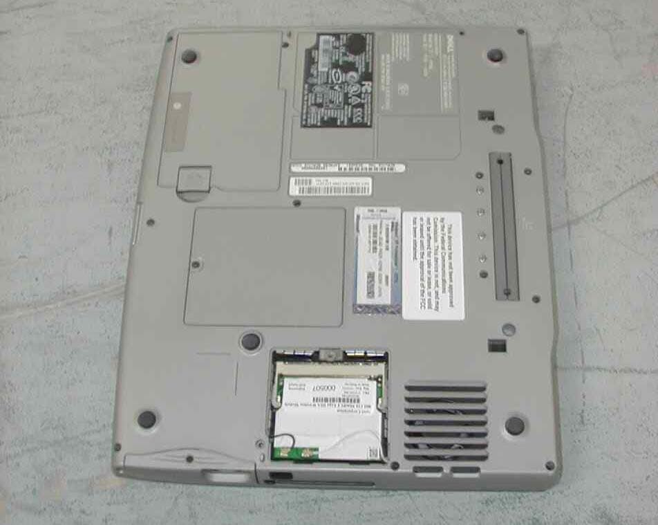
Click to zoom
Application Details
- Equipment Class
- DTS - Digital Transmission System
- Date of Grant
- Feb 26, 2003
- Application Purpose
- Original Equipment
- Date of Application
- Feb 26, 2003
- Equipment Note
- Wireless 2100 LAN 3A Mini PCI Adapter
- Frequency Range
- 2412.00000000 - 2462.00000000
- Company
- Dell Inc.
- Country
- United States
Documents & Files
Document Text
Text extracted from the exhibit documents filed with the FCC. Open a document above to read the original.
Users Manual
www.dell.com | support.dell.com Installing and Configuring the Mini PCI Card5 Installing and Configuring the Mini PCI Card CAUTION: Before performing any of the procedures listed below, read and follow the safety instructions in the System Information Guide or the Owner's Manual that came with your computer. Read the information on the following pages before you complete the setup of your wireless network. Before You Begin Ensure that you have the following items: •Your portable computer •Your Mini PCI card •The CD that came with your wireless Mini PCI card •The Dell™ TrueMobile™ 1180/1300/1400 Wireless Mini PCI Card and Intel ® Pro/Wireless 2100 LAN 3A Mini PCI Adapter Setup Guide •The regulatory label(s) if required in your region For Latitude™ D600/D500 and Inspiron™ 600m/500m Computers Installing the Mini PCI Card 1Ensure that the work surface is flat and clean to prevent the computer cover from being scratched. 2Save and close any open files, exit any open programs, and then shut down the computer. www.dell.com | support.dell.com 6Installing and Configuring the Mini PCI Card 3If the computer is connected to a docking device (docked), undock it. See the documentation that came with your docking device for instructions. 4Disconnect the computer from the electrical outlet. 5Wait 10 to 20 seconds, and then disconnect any attached devices. 6Remove any installed PC Cards, batteries, and module bay devices. NOTICE: Handle components and cards by their edges, and avoid touching pins and contacts. Ground yourself by touching a metal connector on the back of the computer. Continue to ground yourself periodically during this procedure. 7 Turn the computer over. 8Loosen the captive screw from the Mini PCI card cover, and remove the cover. www.dell.com | support.dell.com Installing and Configuring the Mini PCI Card7 9If a Mini PCI card is not already installed, go to step 10. If you are replacing a Mini PCI card, remove the existing card: aDisconnect the Mini PCI card from any attached cables. bRelease the Mini PCI card by spreading the metal securing tabs until the card pops up slightly. cLift the Mini PCI card out of its connector. NOTICE: To avoid damaging the Mini PCI card, never place cables on top of or under the card. NOTICE: The connectors are keyed to ensure correct insertion. If you feel resistance, check the connectors and realign the card. antenna cables (2) www.dell.com | support.dell.com 8Installing and Configuring the Mini PCI Card 10Align the Mini PCI card with the connector at a 45-degree angle, and press the Mini PCI card into the connector until you feel a click. 11Connect the antenna cables to the Mini PCI card. 12Replace the cover and tighten the screw. Attaching the Regulatory Label NOTICE: You must affix the provided label because it is a regulatory requirement. Failure to do so may void your authority to operate the equipment. NOTE: If your kit came with a SIRIM label, attach the label as shown . 1Close the display and turn the computer upside down on a clean, flat work surface. www.dell.com | support.dell.com Installing and Configuring the Mini PCI Card9 2Remove the adhesive cover from the back of the regulatory label and attach the label. NOTE: The label shown is a sample only. It may not exactly represent the characters and words appearing on your enclosed label. For Latitude D800, Inspiron 8500, and Dell Precision™ M60 Computers Installing the Mini PCI Card 1Ensure that the work surface is flat and clean to prevent the computer cover from being scratched. 2Save and close any open files, exit any open programs, and then shut down the computer. SIRIM label Mini PCI card regulatory label www.dell.com | support.dell.com 10Installing and Configuring the Mini PCI Card 3If the computer is connected to a docking device (docked), undock it. See the documentation that came with your docking device for instructions. 4Disconnect the computer from the electrical outlet. 5Wait 10 to 20 seconds, and then disconnect any attached devices. 6Remove any installed PC Cards, batteries, and module bay devices. NOTICE: Handle components and cards by their edges, and avoid touching pins and contacts. Ground yourself by touching a metal connector on the back of the computer. Continue to ground yourself periodically during this procedure. 7 Turn the computer over. 8Loosen the captive screw from the Mini PCI card/modem cover, and remove the cover. www.dell.com | support.dell.com Installing and Configuring the Mini PCI Card11 9If a Mini PCI card is not already installed, go to step 10. If you are replacing a Mini PCI card, remove the existing card: aDisconnect the Mini PCI card from any attached cables. bRelease the Mini PCI card by spreading the metal securing tabs until the card pops up slightly. cLift the Mini PCI card out of its connector. NOTICE: To avoid damaging the Mini PCI card, never place cables on top of or under the card. NOTICE: The connectors are keyed to ensure correct insertion. If you feel resistance, check the connectors and realign the card. Mini PCI card antenna cables (2) www.dell.com | support.dell.com 12Installing and Configuring the Mini PCI Card 10Align the Mini PCI card with the connector at a 45-degree angle, and press the Mini PCI card into the connector until you feel a click. 11Connect the antenna cables to the Mini PCI card. 12Replace the cover and tighten the screw. Attaching the Regulatory Label NOTICE: You must affix the provided label because it is a regulatory requirement. Failure to do so may void your authority to operate the equipment. NOTE: If your kit came with a SIRIM label, attach the label as shown . 1Close the display and turn the computer upside down on a clean, flat work surface. 2Remove the adhesive cover from the back of the regulatory label and attach the label. Mini PCI card antenna cables (2) www.dell.com | support.dell.com Installing and Configuring the Mini PCI Card13 NOTE: The label shown is a sample only. It may not exactly represent the ch…
Text truncated - open the document above for the full version.
Users Manual
Regulatory Information: Intel(R) PRO/Wireless LAN 3A Mini PCI Adapter User's Guide Information For the User Regulatory Information Information for the user Safety Notices The FCC with its action in ET Docket 96-62 has adopted a safety standard for human exposure to radio frequency (RF) electromagnetic energy emitted by FCC certified equipment. The Intel(R) PRO/Wireless 2100 LAN 3A Mini PCI Adapter meets the Human Exposure limits found in OET Bulletin 65, 2001, and ANSI/IEEE C95.1, 1992. Proper operation of this radio according to the instructions found in this manual will result in exposure substantially below the FCC’s recommended limits. The Intel(R) PRO/Wireless 2100 LAN 3A Mini PCI Adapter has been tested and complies with the FCC & Industry Canada SAR (Specific Absorption Rate) requirements operating in a typical laptop configuration. The following safety precautions should be observed: • Do not touch or move antenna while the unit is transmitting or receiving. • Do not hold any component containing the radio such that the antenna is very close or touching any exposed parts of the body, especially the face or eyes, while transmitting. • Do not operate the radio or attempt to transmit data unless the antenna is connected; if not, the radio may be damaged. • Use in specific environments: o The use of wireless devices in hazardous locations is limited by the constraints posed by the safety directors of such environments. o The use of wireless devices on airplanes is governed by the Federal Aviation Administration (FAA). o The use of wireless devices in hospitals is restricted to the limits set forth by each hospital. • Explosive Device Proximity Warning (see below) • Antenna Warning (see below) • Use on Aircraft Caution (see below) • Other Wireless Devices (see below) • Power Supply (Access Point) (see below) Explosive Device Proximity Warning Warning: Do not operate a portable transmitter (such as a wireless network device) near unshielded blasting caps or in an explosive environment unless the device has been modified to be qualified for such use. Antenna Warnings Warning: Intel(R) PRO/Wireless LAN products are not designed for use with high-gain directional antennas. Use of such antennas with these products is illegal. Use On Aircraft Caution Caution: Regulations of the FCC and FAA prohibit airborne operation of radio-frequency wireless devices because their signals could interfere with critical aircraft instruments. Other Wireless Devices Safety Notices for Other Devices in the Wireless Network: Refer to the documentation supplied with wireless Ethernet adapters or other devices in the wireless network. Local Restrictions on 802.11b Radio Usage Caution: Due to the fact that the frequencies used by 802.11b wireless LAN devices may not yet be harmonized in all countries, 802.11b products are designed for use only in specific countries, and are not allowed to be operated in countries other than those of designated use. As a user of these products, you are responsible for ensuring that the products are used only in the countries for which they were intended and for verifying that they are configured with the correct selection of frequency and channel for the country of use. Any deviation from the permissible settings for the country of use is an infringement of national law and may be punished as such. For country-specific information, see the additional compliance information supplied with the product. Wireless interoperability The Intel(R) PRO/Wireless 2100 LAN 3A Mini PCI adapters are designed to be interoperable with any wireless LAN product that is based on direct sequence spread spectrum (DSSS) radio technology and to comply with the following standards: • IEEE Std. 802.1b-1999. Standard on Wireless LAN. • Wireless Fidelity (WiFi) certification, as defined by the WECA (Wireless Ethernet Compatibility Alliance). The Intel(R) PRO/Wireless 2100 LAN 3A Mini PCI adapter and your health The Intel(R) PRO/Wireless 2100 LAN 3A Mini PCI adapter, like other radio devices, emits radio frequency electromagnetic energy. The level of energy emitted by this device, however, is less than the electromagnetic energy emitted by other wireless devices such as mobile phones. The Intel(R) PRO/Wireless 2100 LAN 3A Mini PCI adapter wireless devices operate within the guidelines found in radio frequency safety standards and recommendations. These standards and recommendations reflect the consensus of the scientific community and result from deliberations of panels and committees of scientists who continually review and interpret the extensive research literature. In some situations or environments, the use of the Intel(R) PRO/Wireless 2100 LAN 3A Mini PCI adapter wireless devices may be restricted by the proprietor of the building or responsible representatives of the applicable organization. Examples of such situations include the following: • Using the Intel(R) PRO/Wireless 2100 LAN 3A Mini PCI adapter equipment on board airplanes, or • Using the Intel(R) PRO/Wireless 2100 LAN 3A Mini PCI adapter equipment in any other environment where the risk of interference with other devices or services is perceived or identified as being harmful. If you are uncertain of the policy that applies to the use of wireless devices in a specific organization or environment (an airport, for example), you are encouraged to ask for authorization to use the Intel(R) PRO/Wireless 2100 LAN 3A Mini PCI adapter wireless device before you turn it on. Regulatory information Please refer to the full Grant of equipment document for other restrictions. The Intel(R) PRO/Wireless 2100 LAN 3A Mini PCI adapter wireless network device must be installed and used in strict accordance with the manufacturer's instructions as described in the user documentation that comes with the product. For country-specific approvals, see Radio approvals. Dell Computer Corporation is not responsible for any radio or television interference caused by unauthor…
Text truncated - open the document above for the full version.
Cover Letter(s)
File: R49947 January 21, 2003 American TCB 6731 Whittier Ave. Suite C110 McLean, VA. 22101 Gentlemen: The enclosed documents constitute a formal submittal and application for a Grant of Equipment Authorization pursuant to Subpart C of Part 15 of FCC Rules (CFR 47) regarding intentional radiators. Data within this report demonstrates that the equipment tested complies with the FCC limits for intentional radiators. This application is for approval of an 802.11b Wireless LAN Mini PCI card installed in a Dell PP05L chassis. This chassis is used by the Inspiron and Latitude series of laptops (please refer to the attestation letter from Dell included with this application). This chassis may also contain a wireless BlueTooth module, approved as a modular device under FCC ID IXMUB22111S. The grant for this modular prohibits co-location with other transmitters. The RF safety exhibits for this application argue that the separation between the antennas of the two devices, combined with the substantially higher output power of the 802.11b device demonstrate that the two modules are not considered to have been co-located. Elliott Laboratories, as duly authorized agent prepared this submittal. A copy of the letter of our appointment as agent is enclosed. If there are any questions or if further information is needed, please contact Elliott Laboratories for assistance. Sincerely, Mark Briggs Director of Engineering MB/bab Enclosures: Agent Authorization Letter Emissions Test Report with Exhibits Attestation Letter describing the host chassis
Cover Letter(s)
51 Spectrum Way Tel (613) 820-2730 Email: [email protected] Nepean, Ontario Fax (613) 820-4161 HTTP://www.aprel.com Canada K2R 1E6 7 th February 2003 Mr. Robert Paxman Intel Corporation 2300 Corporate Center Drive Thousand Oaks, CA 91320 Reference FCC ID: E2K24CLNS Dear Mr. Paxman, Enclosed are the responses to the questions set by Mr. Dennis Ward ATCB. I have only answered the questions, which address the areas of the project executed by APREL Laboratories. Question 4. Page 15 states that conducted power was 17.6dBm, page 3 says 17.8dBm. Please make documentation consistent. The maximum conducted power, which was assessed by APREL Laboratories, was measured at 17.8dBm, which was measured on the Mid and High channels for the device(s) tested. A conducted power measurement of 17.5dBm was measured for the low channel. Depending on the channel where the conservative SAR was measured the power level changed. The table located on page 15 of the SAR report should have shown the average conducted power measured for all channels after correction. This value should have read 17.7dBm. It must be noted that this table is provided to show no power drift was measured during the experimental analysis. The statement on page 3 of the SAR report is correct, where the maximum measured conducted power for the device tested was 17.8dBm. Question 6. Please note that the SAR report contains hand SAR testing. Since there is no approved FCC approach to this sort of SAR, this data needs to be removed from the report. Please report Body SAR only. It is the understanding of APREL Laboratories that the term Hand SAR has been replaced with the definition of Direct Contact SAR. Direct Contact SAR deals with analysis of extremities, and as the hand is classed as an extremity the reported 10g average values are necessary to prove conformance for the device(s) tested. I would recommend that you request from the ATCB audit engineer an official FCC public release where it is clearly stated that “Direct Contact SAR” is no longer required to prove conformity of a device tested. It is the opinion of APREL Laboratories that by removing the results in question the FCC will be in a position to with draw or suspend the grant as issued until the data is provided. 51 Spectrum Way Tel (613) 820-2730 Email: [email protected] Nepean, Ontario Fax (613) 820-4161 HTTP://www.aprel.com Canada K2R 1E6 Question 7. On page 4 of the SAR report you state that the max SAR with only the WLAN transmitting, the SAR was 1.16w/kg. Then you state that with both the WLAN and Bluetooth transmitting simultaneously the SAR was 0.94w/kg. The explanation only states that you performed additional testing. If both devices were transmitting at maximum power and since the manufacturer has stated that the antennae for both devices are separated by more than 20cm (thus no collocation) I would expect that the SAR would be about the same, but certainly not decrease. This decrease can be for a number of reasons. One primary cause may be power. Please verify that the power of each device during this test was at maximum and that the power of each device was not adversely reduced due to simultaneous operation. If power was reduced, please provide how this is part of the normal operation, or alternately, provide an explanation of the decreased power. (See also Neweb antenna SAR report) For both of the experimental analysis exercises executed by APREL Laboratories (both SAR reports) it was not possible for conducted power measurements to be made on the Bluetooth device. APREL Laboratories recommend that the conservative SAR measured, which represents the analysis made on the 802.11b module, be reported in the grant. As a lower value was assessed while the Bluetooth and 802.11b module were transmitting at the same time the term “Conservative” does not apply and as such would not be acceptable for the FCC. As the conservative SAR value has been recorded and reported APREL do not see the need for additional analysis or explanation as to why lower values were assessed. Where the lower number was to be used in the grant then it would be acceptable for a request for additional data to be presented (where this recorded value is not termed as conservative). It is the understanding of APREL Laboratories that the “Conservative” assessed SAR value of 1.16 W/kg is to be used on the grant. Question 8. Please note that SAR measurements are to have power drift included in the data for each plot. I cannot find power drift information on the plot or plot data sheets. Please provide the required power drift information on the plotted data. The following paragraphs should have been included in both reports on page 15. The device was set to transmit for a period of 30 minutes (exceeded scan time) and conducted power measurements were made at 5-minute intervals to gauge power drift. Over the course of the 30-minute period no power drift was measured. The same process was executed as above while the Bluetooth device was set to transmit and the power was assessed, no power drift was measured. The table on page 15 for both SAR reports indicate that no power drift was measured throughout the assessment process. In future applications APREL Laboratories shall repeat this information on the plot data pages. 51 Spectrum Way Tel (613) 820-2730 Email: [email protected] Nepean, Ontario Fax (613) 820-4161 HTTP://www.aprel.com Canada K2R 1E6 Question 9. Page 26 and 36 of the Hitachi SAR report (Product Data) says the transmit power was 1 Watt. Is this the EUT power? Please explain what this 1 Watt is referring to. The transmit power for the device was not 1Watt. This value reflects the normalised power value for the system validation, and is a field, which should be updated by the metrology engineer who executed the analysis prior to the start of the assessment process. This 1W value has no effect on the measurement process or the results. The value recorded is a result of the test reports generated by the syst…
Text truncated - open the document above for the full version.
External Photos
External Photographs Picture Showing Placement Of 802.11b Card In The Laptop WLAN card installed in mini PCIslot in laptop base
Internal Photos
FCC ID: PD9WM3A2100 Top View “Insulation removed” FCC ID: PD9WM3A2100 Bottom View “Insulation removed” FCC ID: PD9WM3A2100 Top View “Shielding removed” FCC ID: PD9WM3A2100 Top View “Insulation Added” FCC ID: PD9WM3A2100 Bottom View “Insulation Added”
RF Exposure Info
Page 1 of 54 ITLB-DELL-Single Band Mini PCI Type 3a-3976 51 Spectrum Way Tel. (613) 820-2730 Nepean, Ontario, K2R 1E6 Fax (613) 820 4161 e-mail: [email protected] © APREL 2002 This report shall not be reproduced, except in full, without the express written approval of APREL Laboratories. Experimental Analysis SAR Report Subject: Specific Absorption Rate (SAR) Hand and Body Report Product: Intel Mini PCI Type 3A 802.11b Wireless LAN Adapter model WM3A2100 inside Dell laptop chassis model number PP05L Model: PP05L Applicant: Intel Corporation 2300 Corporate Center Drive Thousand Oaks, CA 91320 Manufacturer: Dell Computer Corporation One Dell Way Round Rock, TX 78613 Project #: ITLB-DELL-Single Band Mini PCI Type 3a-3976 Prepared by: APREL Laboratories 51 Spectrum Way Nepean, Ontario K2R 1E6 Approved by ___________________________ Date: ________________ Stuart Nicol Director Product Development, Dosimetric R&D Submitted by ____________________________ Date: _________________ Jay Sarkar Technical Director of Standards & Certification Released by _____________________________ Date: _________________ Dr. Jacek J. Wojcik, P. Eng. PP05L Page 2 of 54 ITLB-DELL-Single Band Mini PCI Type 3a-3976 51 Spectrum Way Tel. (613) 820-2730 Nepean, Ontario, K2R 1E6 Fax (613) 820 4161 e-mail: [email protected] © APREL 2002 This report shall not be reproduced, except in full, without the express written approval of APREL Laboratories. Applicant: Intel Corporation Manufacturer: Dell Computer Corporation FCC ID: E2K24CLNS Equipment: Intel Mini PCI Type 3A 802.11b Wireless LAN Adapter model WM3A2100 inside Dell laptop chassis model number PP05L Model: PP05L Standard: FCC 96-326, Guidelines for Evaluating the Environmental Effects of Radio-Frequency Radiation ENGINEERING SUMMARY This report contains the results of the engineering evaluation performed on the Intel Mini PCI Type 3A 802.11b Wireless LAN Adapter model WM3A2100 inside Dell laptop chassis model number PP05L. The analysis was carried out in accordance with the requirements of FCC 96-326, Guidelines for Evaluating the Environmental Effects of Radio-Frequency Radiation in accordance with Supplement C and, using methodologies contained within IEEE P-1528. The Intel Mini PCI Type 3A 802.11b Wireless LAN Adapter model WM3A2100 inside Dell laptop chassis model number PP05L was evaluated for compliance to the RF exposure requirements contained in section 2. “Applicable Documents”. The Intel Mini PCI Type 3A 802.11b Wireless LAN Adapter model WM3A2100 inside Dell laptop chassis model number PP05L was assessed for SAR at the maximum available power level of 17.8dBm while operating with the duty cycle set at 100%. The Intel Pro/Wireless 2100 WLAN Mini-PCI Type 3A Adapter is an internally located unit tested with an internal Hitachi antenna. The Intel Pro/Wireless 2100 WLAN Mini-PCI Type 3A Adapter has no body worn applications and can only function while located within the Dell laptop chassis model number PP05L. The Intel Pro/Wireless 2100 WLAN Mini-PCI Type 3A Adapter has been developed as an OEM module, which shall be integrated within the Dell laptop chassis model number PP05L by the laptop manufacturer. The Intel Pro/Wireless 2100 WLAN Mini-PCI Type 3A Adapter was integrated by APREL for the purpose of the analysis. The Dell laptop chassis model number PP05L is a production model, which has a set of integrated antennas. The antennas are not visible to the user. The Dell laptop chassis model number PP05L as tested incorporated a low power Bluetooth module (<1mW), along with the Intel Pro/Wireless 2100 WLAN Mini-PCI Type 3A Adapter operating at the 802.11b standard. Activation codes were provided to APREL for the purpose of this analysis, which enabled the engineer to set the operational parameters of the SAR assessment (frequency and Tx power). Page 3 of 54 ITLB-DELL-Single Band Mini PCI Type 3a-3976 51 Spectrum Way Tel. (613) 820-2730 Nepean, Ontario, K2R 1E6 Fax (613) 820 4161 e-mail: [email protected] © APREL 2002 This report shall not be reproduced, except in full, without the express written approval of APREL Laboratories. For the purpose of the SAR analysis executed and subsequent report the Dell laptop chassis model number PP05L, which incorporated the Intel Pro/Wireless 2100 WLAN Mini-PCI Type 3A Adapter operating at the 802.11b standard and Bluetooth module will be called the DUI (Device Under Investigation). The Dell laptop chassis model number PP05L incorporating the Intel Pro/Wireless 2100 WLAN Mini-PCI Type 3A Adapter was evaluated for both body exposure and direct contact SAR (extremities) at low (ch#1), middle (ch#6) and high (ch#11) for the frequency range of 2412MHz to 2462MHz. Tests were executed at zero separation distance, for direct contact SAR (extremities) and, a 10mm separation distance for body analysis. Further analysis was made of the Intel Pro/Wireless 2100 WLAN Mini-PCI Type 3A Adapter while the Bluetooth device was transmitting, at the low mid, and high channels. The results of this additional analysis are presented in this report. The conservative 10g average for direct contact SAR analysis (hand/extremities) was found to be 0.50 W/kg for the peak RF output power of the low channel (ch#1, f=2412MHz) for the left side of the Dell laptop chassis model number PP05L at 0 mm separation. A further analysis was performed while the Bluetooth device was transmitting synchronously with the 802.11b module and the conservative 10g average was found to be 0.87 W/kg at the mid channel (ch#6, f=24737MHz). For body SAR analysis a separation distance of 5 mm from the left side of the Dell laptop chassis model number PP05L was assessed where the conservative 1g SAR was found to be 1.16 W/kg for the peak RF output power of the Mid channel (ch#6, f=2437MHz). A further analysis was performed while the Bluetooth device was transmitting synchronously with the 802.11b module and the conservative 1g average was found to be 0.94 W/kg at the low channel (ch#1, f=241…
Text truncated - open the document above for the full version.
RF Exposure Info
Page 1 of 57 ITLB-DELL-Single Band Mini PCI Type 3a-397751 Spectrum Way Tel. (613) 820-2730 Nepean, Ontario, K2R 1E6 Fax (613) 820 4161 e-mail: [email protected] © APREL 2002 This report shall not be reproduced, except in full, without the express written approval of APREL Laboratories. Experimental Analysis SAR Report Subject: Specific Absorption Rate (SAR) Hand and Body Report Product: Intel Mini PCI Type 3A 802.11b Wireless LAN Adapter model WM3A2100 inside Dell laptop chassis model number PP05L Model: PP05L Client: DELL Computers Applicant: Intel Corporation 2300 Corporate Center Drive Thousand Oaks, CA 91320 Manufacturer: Dell Computer Corporation One Dell Way Round Rock, TX 78613 Project #: ITLB-DELL-Single Band Mini PCI Type 3a-3977 Prepared by: APREL Laboratories 51 Spectrum Way Nepean, Ontario K2R 1E6 Approved by ___________________________ Date: ________________ Stuart Nicol Director Product Development, Dosimetric R&D Submitted by ____________________________ Date: _________________ Jay Sarkar Technical Director of Standards & Certification Released by _____________________________ Date: _________________ Dr. Jacek J. Wojcik, P. Eng. PP05L Page 2 of 57 ITLB-DELL-Single Band Mini PCI Type 3a-397751 Spectrum Way Tel. (613) 820-2730 Nepean, Ontario, K2R 1E6 Fax (613) 820 4161 e-mail: [email protected] © APREL 2002 This report shall not be reproduced, except in full, without the express written approval of APREL Laboratories. Applicant: Intel Corporation Manufacturer: Dell Computer Corporation FCC ID: E2K24CLNS Equipment: Intel Mini PCI Type 3A 802.11b Wireless LAN Adapter model WM3A2100 inside Dell laptop chassis model number PP05L Model: PP05L Standard: FCC 96-326, Guidelines for Evaluating the Environmental Effects of Radio-Frequency Radiation ENGINEERING SUMMARY This report contains the results of the engineering evaluation performed on the Intel Mini PCI Type 3A 802.11b Wireless LAN Adapter model WM3A2100 inside Dell laptop chassis model number PP05L. The analysis was carried out in accordance with the requirements of FCC 96-326, Guidelines for Evaluating the Environmental Effects of Radio-Frequency Radiation in accordance with Supplement C and, using methodologies contained within IEEE P-1528. The Intel Mini PCI Type 3A 802.11b Wireless LAN Adapter model WM3A2100 inside Dell laptop chassis model number PP05L was evaluated for compliance to the RF exposure requirements contained in section 2. “Applicable Documents”. The Intel Mini PCI Type 3A 802.11b Wireless LAN Adapter model WM3A2100 inside Dell laptop chassis model number PP05L was assessed for SAR at the maximum available power level of 17.8dBm while operating with the duty cycle set at 100%. The Intel Pro/Wireless 2100 WLAN Mini-PCI Type 3A Adapter is an internally located unit tested with an internal Neweb antenna. The Intel Pro/Wireless 2100 WLAN Mini-PCI Type 3A Adapter has no body worn applications and can only function while located within the Dell laptop chassis model number PP05L. The Intel Pro/Wireless 2100 WLAN Mini-PCI Type 3A Adapter has been developed as an OEM module, which shall be integrated within the Dell laptop chassis model number PP05L by the laptop manufacturer. The Intel Pro/Wireless 2100 WLAN Mini-PCI Type 3A Adapter was integrated by APREL for the purpose of the analysis. The Dell laptop chassis model number PP05L is a production model, which has a set of integrated antennas. The antennas are not visible to the user. The Dell laptop chassis model number PP05L as tested incorporated a low power Bluetooth module (<1mW), along with the Intel Pro/Wireless 2100 WLAN Mini-PCI Type 3A Adapter operating at the 802.11b standard. Activation codes were provided to APREL for the purpose of this analysis, which enabled the engineer to set the operational parameters of the SAR assessment (frequency and Tx power). Page 3 of 57 ITLB-DELL-Single Band Mini PCI Type 3a-397751 Spectrum Way Tel. (613) 820-2730 Nepean, Ontario, K2R 1E6 Fax (613) 820 4161 e-mail: [email protected] © APREL 2002 This report shall not be reproduced, except …
Text truncated - open the document above for the full version.
Contact Information
Applicant
Don A Bobo(Distinguished Member of Technical Staff)
Technical Contact
Elliott Laboratories IncMark Briggs
[email protected]408-245-7800
684 West Maude Avenue · Sunnyvale, California · United States
Test Firm
Elliott Laboratories LLCDavid Bare
Technical Specifications
| # | Rule Parts | Frequency Range | Power Output |
|---|---|---|---|
| 1 | 15C | 2.41 GHz - 2.46 GHz | 44.00 mW |
Other Applications from Dell Inc.
E2K-DWRFID2601
Aug 17, 2026RFID 13.56MHz Wireless Module
Equipment Class
DXX - Part 15 Low Power Communication Device TransmitterE2K-DWRFID2501
May 04, 2026RFID 13.56MHz Wireless Module
Equipment Class
DXX - Part 15 Low Power Communication Device Transmitter
E2K-DWRFID2406
Sep 30, 2025RFID 13.56MHz Wireless Module
Equipment Class
DXX - Part 15 Low Power Communication Device Transmitter
E2K-DRU77440
Dec 01, 20245G NR Remote Radio Unit 4TX 4RX 40W-per-TX
Equipment Class
TNB - Licensed Non-Broadcast Station Transmitter
E2K-DWRFID2401
Oct 03, 2024RFID 13.56MHz Wireless Module
Equipment Class
DXX - Part 15 Low Power Communication Device Transmitter