E2KWM3945ABGIntel PRO/Wireless 3945ABG Network Connection
Dell Inc.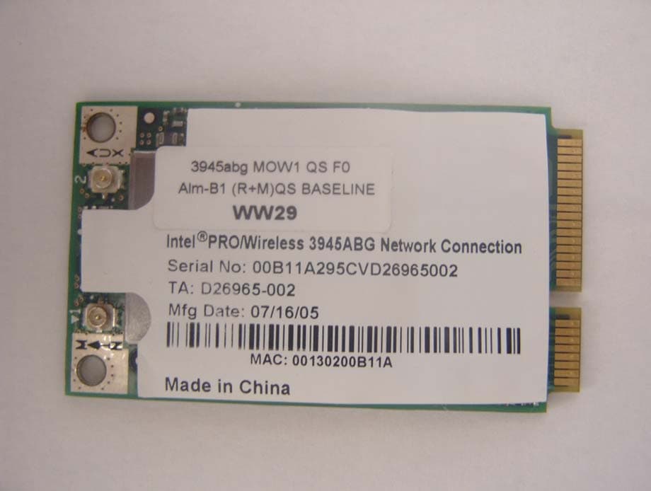
Click to zoom
Application Details
- Equipment Class
- NII - Unlicensed National Information Infrastructure TX
- Date of Grant
- Dec 04, 2005
- Application Purpose
- Original Equipment
- Date of Application
- Dec 04, 2005
- Equipment Note
- Intel PRO/Wireless 3945ABG Network Connection
- Frequency Range
- 5260.00000000 - 5320.00000000
- Company
- Dell Inc.
- Country
- United States
Documents & Files
Document Text
Text extracted from the exhibit documents filed with the FCC. Open a document above to read the original.
Users Manual
Intel(R) PRO/Wireless 3945ABG Network Connection User Guide With your wireless network card, you can access wireless networks, share files or printers, or even share your Internet connection. All of these features can be explored with a wireless network in your home or office. This wireless local area network (WLAN) solution is designed for both home and business use. Additional users and features can be added as your networking needs grow and change. Your Intel(R) PRO/Wireless 3945ABG Network Connection adapter is compatible with 802.11a, 802.11b and 802.11g wireless standards. Operating at 5 GHz or 2.4 GHz frequency at speeds of up to 54 Mbps you can now connect your computer to existing high-speed networks that use multiple access points within large or small environments. Your wireless adapter maintains automatic data rate control according to access point location to achieve the fastest possible connection. All of your wireless network connections are easily managed by Intel(R) PROSet/Wireless software. Profiles that are set up through the Intel PROSet/Wireless software provide enhanced security measures with 802.1x network authentication. NOTE: The software is compatible with the Intel(R) PRO/Wireless 2915ABG Network Connection and the Intel(R) PRO/Wireless 2200BG Network Connection. Table of Contents l Use Intel PROSet/Wireless Software l Connect to a Network l Use Profiles l Set up Security l Troubleshooting l Administrator Tool l Glossary l Wireless Network Overview l Security Overview l Specifications l Customer Support l Safety and Regulatory Information l Warranty l Adapter Registration Information in this document is subject to change without notice. © 2004–2005 Intel Corporation. All rights reserved. Intel Corporation, 5200 N.E. Elam Young Parkway, Hillsboro, OR 97124-6497 USA The copying or reproducing of any material in this document in any manner whatsoever without the written permission of Intel Corporation is strictly forbidden. Intel(R) is a trademark or registered trademark of Intel Corporation or its subsidiaries in the United States and other countries. Other trademarks and trade names may be used in this document to refer to either the entities claiming the marks and names or their products. Intel disclaims any proprietary interest in trademarks and trade names other than its own. Microsoft and Windows are registered trademarks of Microsoft Corporation. *Other names and brands may be claimed as the property of others. Intel Corporation assumes no responsibility for errors or omissions in this document. Nor does Intel make any commitment to update the information contained herein. "Important Notice FOR ALL USERS OR DISTRIBUTORS!!!! Intel wireless LAN adapters are engineered, manufactured, tested, and quality checked to ensure that they meet all necessary local and governmental regulatory agency requirements for the regions that they are designated and/or marked to ship into. Since wireless LANs are generally unlicensed devices that share spectrum with radars, satellites, and other licensed and unlicensed devices, it is sometimes necessary to dynamically detect, avoid, and limit usage to avoid interference with these devices. In many instances Intel is required to provide test data to prove regional and local compliance to regional and governmental regulations before certification or approval to use the product is granted. Intel's wireless LAN's EEPROM, firmware, and software driver are designed to carefully control parameters that affect radio operation and to ensure electromagnetic compliance (EMC). These parameters include, without limitation, RF power, spectrum usage, channel scanning, and human exposure. For these reasons Intel cannot permit any manipulation by third parties of the software provided in binary format with the wireless WLAN adapters (e.g., the EEPROM and firmware). Furthermore, if you use any patches, utilities, or code with the Intel wireless LAN adapters that have been manipulated by an unauthorized party (i.e., patches, utilities, or code (including open source code modifications) which have not been validated by Intel), (i) you will be solely responsible for ensuring the regulatory compliance of the products, (ii) Intel will bear no liability, under any theory of liability for any issues associated with the modified products, including without limitation, claims under the warranty and/or issues arising from regulatory non-compliance, and (iii) Intel will not provide or be required to assist in providing support to any third parties for such modified products. Note: Many regulatory agencies consider Wireless LAN adapters to be "modules", and accordingly, condition system-level regulatory approval upon receipt and review of test data documenting that the antennas and system configuration do not cause the EMC and radio operation to be non-compliant." July 2005 Back to Contents Use Intel(R) PROSet/Wireless Software: Intel(R) PRO/Wireless 3945ABG Network Connection User Guide l Use Intel PROSet/Wireless as your Wireless Manager l Start Intel PROSet/Wireless l Start Intel PROSet/Wireless from the Taskbar m Taskbar Icons m Tool Tips and Desktop Alerts l Intel PROSet/Wireless Main Window m Wireless Networks List m Connection Status Icons m Network Properties m Connection Details m Profiles List l Intel PROSet/Wireless Menus l Tools Menu m Application Settings m Intel Wireless Troubleshooter m Administrator Tool l Advanced Menu m Adapter Settings m Advanced Statistics m Use Windows to manage Wi-Fi l Profiles Menu m Manage Profiles m Import/Export m Manage Exclusions l Enable and Disable the Radio l Install and Uninstall the Software Use Intel PROSet/Wireless as your Wireless Manager Intel(R) PROSet/Wireless is used to setup, edit and manage network profiles to connect to a network. It also includes advanced settings such as power management and channel selection for setting up ad- hoc networks. If you use Microsoft(R) Windows(R) XP Wireless Zero Confi…
Text truncated - open the document above for the full version.
Cover Letter(s)
American Telecommunications Certification Body Inc. 6731 Whittier Ave, McLean, VA 22101 December 1, 2005 RE: FCC ID: E2KWM3945ABG_ATCB002985 Attention: Johnny Candelas I have a few comments on this Application. Please note that further comments may arise in response to answers provided to the questions below. 1. Please note that the manual mentions wall or pole mounted high gain antenna(s) which are professionally installed. However, the antenna(s) tested with this device are not considered high gain antenna(s). Please note that only those antenna(s) tested with this device or antenna(s) of the same type with equal or lower gain can be used. Any use of the type antenna mentioned in the manual as ‘wall mount or pole mounted” high gain antenna(s) is not allowed unless they are tested and shown compliant. Please either remove such notice from the manual or please provide evidence that the rf exposure distances mentioned can be met. 2. Please note that the manual states, “As a user of these products, you are responsible for ensuring that the products are used only in the countries for which they were intended and for verifying that they are configured with the correct selection of frequency and channel for the country of use.” This indicates that the device frequency may have the possibility of being changed by the end user so that an illegal frequency may be used in the US. Please note that the rules specifically state that a device must be manufactured in such a way that “adjustments of any control that is readily accessible by or intended to be accessible to the user will not cause operation of the device in violation of the regulations.” This includes any software or downloadable drivers (Intel only) that will allow the user to change the frequencies so as to operate the device illegally. Please verify and attest (show evidence) how the user cannot change any ‘readily accessible or intended accessible control’ so as to operate the US version of this device outside allowed US frequencies. 3. Please note that as this is a Modular approval the device must be tested in stand alone mode. Please note that the test set up photos do not clearly show this device as being tested in stand alone configuration. Please clearly show where this device is in the radiated and conducted test setup photos. 4. FYI – no action needed. Please note that the assumed 68.3dBuV/m limit representing -27dBm may not address all situations adequately as it assumes certain factors such as an isotropic gain of 0dBi that may not actually apply. The correct method of determining compliance to the -17dBm limit is to use the formula (ed)^2/30G. The reason the generic limit 68.3dBuV/m may not address all situations is that it does not include any information about the transmitting device antenna; and this must be considered. For example a spurious emissions reading of 68.3dBuV/m for a 0dBi gain antenna and the same reading for a 5 dBi gain and -5dBi gain antenna does not calculate to be the same EIRP. Even though the 68.3dBuV/m value is obtained from both situations the 0dBi antenna would yield an EIRP of -27dBm, while the EIRP of the 5dBi gain antenna would be - 31dBm and the EIRP of an antenna with -5dBi gain would be -21dBm. While the erroneous 68.3dBuV/m limit may work for gains greater than 0dBi, they can be very misleading for any antenna whose gain is less the 0dBi. Please consider these facts in future tests. 5. Please verify that this device does not have a turbo mode at 5.25GHz. 6. Please note that IC testing should be done using the most current RSS210 issue 6. While testing may be similar, the references in the specified standards are different. Please address this issue. z Page 2 December 1, 2005 Dennis Ward mailto:[email protected] The items indicated above must be submitted before processing can continue on the above referenced application. Failure to provide the requested information may result in application termination. Correspondence should be considered part of the permanent submission and may be viewed from the Internet after a Grant of Equipment Authorization is issued. Please do not respond to this correspondence using the email reply button. In order for your response to be processed expeditiously, you must submit your documents through the AmericanTCB.com website. Also, please note that partial responses increase processing time and should not be submitted. Any questions about the content of this correspondence should be directed to the sender.
Cover Letter(s)
December 05, 2005 RE: Dell Computer Corporation FCC ID: E2KWM3945ABG Answers to the ATCB comments on the above referenced Application. 1. Please note that the manual mentions wall or pole mounted high gain antenna(s) which are professionally installed. However, the antenna(s) tested with this device are not considered high gain antenna(s). Please note that only those antenna(s) tested with this device or antenna(s) of the same type with equal or lower gain can be used. Any use of the type antenna mentioned in the manual as ‘wall mount or pole mounted” high gain antenna(s) is not allowed unless they are tested and shown compliant. Please either remove such notice from the manual or please provide evidence that the rf exposure distances mentioned can be met. Per the manufacture, wall or pole mounted high gain antennas will be professionally installed and tested in the future if used. 2. Please note that the manual states, “As a user of these products, you are responsible for ensuring that the products are used only in the countries for which they were intended and for verifying that they are configured with the correct selection of frequency and channel for the country of use.” This indicates that the device frequency may have the possibility of being changed by the end user so that an illegal frequency may be used in the US. Please note that the rules specifically state that a device must be manufactured in such a way that “adjustments of any control that is readily accessible by or intended to be accessible to the user will not cause operation of the device in violation of the regulations.” This includes any software or downloadable drivers (Intel only) that will allow the user to change the frequencies so as to operate the device illegally. Please verify and attest (show evidence) how the user cannot change any ‘readily accessible or intended accessible control’ so as to operate the US version of this device outside allowed US frequencies. Refer to “Channel attestation E2KWM3945ABG” exhibit. 3. Please note that as this is a Modular approval the device must be tested in stand alone mode. Please note that the test set up photos do not clearly show this device as being tested in stand alone configuration. Please clearly show where this device is in the radiated and conducted test setup photos. Refer to “Photographs – Test Setup – Rev. A” exhibit. 5. Please verify that this device does not have a turbo mode at 5.25GHz. This device does not operate in turbo mode on any channel. 6. Please note that IC testing should be done using the most current RSS210 issue 6. While testing may be similar, the references in the specified standards are different. Please address this issue. For the 2400 – 2483.5 MHz band report the new RSS210 issue 6 is referenced. For 5150 – 5350 MHz band we still reference RSS210 issue 5 because we did not test for DFS and TPC. According to Annex 9 of RSS210 issue 6 we can still use RSS210 issue 5 for this frequency band. See text below from RSS210 issue 6 Annex 9. Annex 9: Local Area Network Devices This annex provides standards for licence-exempt local area network (LE-LAN) devices operating in the 5150-5350 MHz and 5470-5825 MHz bands. Devices operating in the 5250-5350 MHz which do not comply with the provisions in this annex but only with the requirements in RSS-210, Issue 5 will be allowed to be certified until May 1, 2008. After that date, devices operating in this band shall be certified only if they comply with the provisions in this annex.
Cover Letter(s)
AEGIS LABS, INC 22431 Antonio Parkway B160-417, Rancho Santa Margarita, CA 92688 949-459-7886 TEL 949-459-7869 FAX www.aegislabsinc.com TRANSMITTER MODULAR APPROVAL ATTESTATION November 28, 2005 Federal Communications Commission Re: Application Modular Approval Certification for FCC ID: E2KWM3945ABG Gentlemen: The following attestation addresses the eight requirements to support modular approval as required by the FCC Public Notice DA00-1407 “Part 15 Unlicensed Modular Transmitter Approval” 1 The modular transmitter has its own RF shielding and does not rely upon the shielding provided by the device into which it is installed in order to comply with Part 15 limits. 2 The modular transmitter has buffered modulation/data inputs. All inputs to the modules are buffered through the radio circuitry. 3 The modular transmitter has its own power supply regulator. 4 The modular transmitter has an antenna that complies with section 15.203 and 15.204(c) of the FCC rules. It has a UFL type of connector at the transmitter end and is soldered to the antenna (depending on OEM configuration). Also the antenna will be internal in the OEM host equipment and inaccessible to the user. 5 The modular transmitter was tested outside of a host desktop computer using a PCI extender card. The PCI extender card allows the transmitter to be placed outside of the chassis of the host desktop computer. 6 The modular transmitter will be labeled with its own FCC ID. Also, the OEM host computer manufacturer will be informed to display a label referring to the enclosed module. The exterior label will read as follows: “Contains Transmitter Module FCC ID” or “Contains TXFCCID”. 7 The modular transmitter is manufactured so that the user cannot influence the operation of the transmitter that will operate outside of the scope of the regulations. 8 The modular transmitter meets the MPE calculations of 47 CFR 1.1307(b)(1). If there are any additional questions or if further information is needed, please contact us at your earliest convenience at (949) 459-7886. Sincerely, Johnny Candelas Aegis Labs, Inc. Test Technician
Cover Letter(s)
1 Antenna Regulatory Information z Product type z WLAN antenna z Model number z DELL Travis (HAL00) z Revision z A01 z Manufacturer Part No. : Main / Aux z S03011-L-1-FPCB z S03011-R-FPCB z Dell Part No. : Main / Aux z DC330007L0L/DC330007M0L Amphenol Shanghai Amphenol Airwave Communication Electronics Co., LTD No. 88 Lai Ting S. Rd, Jiu Ting, Song Jiang, Shanghai, China (201615) 2 1. Specifications Antenna Specifications Remark: Peak Gains include all system losses (connector, cable, etc) Cable Specifications Antenna Type (Material, Technology) Flex, Inverted-F Antenna (IFA) Antenna Model Number DELL Travis (HAL00) Operating Frequency Range(s) 2.4GHz ~ 2.5GHz and 4.9GHz ~ 5.9GHz Peak Gain (802.11b/g / 2.4GHz Band) (dBi) -0.26 dBi Peak Gain (802.11a / 5GHz Band) (dBi) 2.66 dBi Radio Connector Type IPEX 20308-111R-32/ 20363-111R-37 or equivalent connector Mid-Line Connector Type (If Applicable) N/A Main Aux Cable Parameters LCD Side Base Side Total LCD Side Base Side Total Length (mm) N/A N/A 493 N/A N/A 543 Loss (Including Connectors) (dB, 2.4GHz / 5GHz) 1.27/ 2.10 1.39 / 2.23 Description (Color, Diameter, Manufacturer) Color: White OD: 1.32~1.37 mm Vendor: GBE or equivalent Color: Black OD: 1.32~1.37 mm Vendor: GBE or equivalent 3 2. Antenna Assembly 3. Antenna Assembly Installed in The Notebook Aux Antenna Main Antenna 4 4. Mechanical Drawing of Antennas Note: (1) is the Main WLAN cable (4) is the Auxiliary WLAN cable 5 5. Gain Patterms - Main Antenna 6 7 - Aux Antenna 8
Cover Letter(s)
Regulatory WLAN Antenna Information for ZRS Hitachi Cable, Ltd 1-6-1, Otemachi, Chiyoda-ku, Tokyo, Japan Antenna Specifications Note: Peak Gain should include all system losses (connector, cable, etc) Cable Specifications Note: For single cable assembly (no mid-line connector), use the 'Total' column for each cable length and list N/A in the ‘LCD’ and ‘Base’ fields Cable Loss should be reported for the total cable assembly (for both Main and Aux antennas) Antenna Type (Material, Technology) Main ; Monopole Type Aux ; PIFA Type Antenna Model Number HMT05/HFT17-DL07 Operating Frequency Range(s) 2.40 – 2.4835 GHz / 4.90 – 5.875 GHz Peak Gain (802.11b/g / 2.4GHz Band) (dBi) Main 1.5 / Aux 3.0 Peak Gain (802.11a / 5GHz Band) (dBi) Main 5.1 / Aux 5.4 Radio Connector Type Micro Coaxial Connector Mid-Line Connector Type (If Applicable) NA Main Aux Cable Parameters LCD Side Base Side Total LCD Side Base Side Total Length (mm) NA NA 385 NA NA 478 Loss (Including Connectors) (dB) 2.4 GHz / 5 GHz 1.0/1.6 1.3/2.2 Description (Color, Diameter, Manufacturer) White φ 1.37 mm Hitachi Cable Black φ 1.37 mm Hitachi Cable (a) Main Antenna (b) Aux Antenna Picture of Antenna installed in the notebook Picture of Antenna 1.0 V + H Peak Gain (dBi) -0.2 Horizontal Peak Gain (dBi) -0.8 Vertical Peak Gain (dBi) 2412 Frequency (MHz) 1.7 V + H Peak Gain (dBi) -0.8 Horizontal Peak Gain (dBi) -0.7 Vertical Peak Gain (dBi) 2437 Frequency (MHz) 1.6 V + H Peak Gain (dBi) -1.1 Horizontal Peak Gain (dBi) -1.1 Vertical Peak Gain (dBi) 2462 Frequency (MHz) Main Antenna (1) 2.412 GHz Vertic alHorizontalV+H 90° 270° 180° 2.437 GHz Vertic alHorizontalV+H 90° 270° 180° 2.462 GHz Vertic alHoriz ontalV+ H 90° 270° 180° 1.3 V + H Peak Gain (dBi) 0.3 Horizontal Peak Gain (dBi) -0.1 Vertical Peak Gain (dBi) 4900 Frequency (MHz) 2.9 V + H Peak Gain (dBi) -0.1 Horizontal Peak Gain (dBi) 1.9 Vertical Peak Gain (dBi) 5150 Frequency (MHz) 3.5 V + H Peak Gain (dBi) 1.3 Horizontal Peak Gain (dBi) 1.4 Vertical Peak Gain (dBi) 5350 Frequency (MHz) Main Antenna (2) 4.900 GHz Vertic alHorizontalV+H 90° 270° 180° 5.150 GHz Vertic alHorizontalV+H 90° 270° 180° 5.350 GHz Vertic alHoriz ontalV+H 90° 270° 180° 4.0 V + H Peak Gain (dBi) 2.5 Horizontal Peak Gain (dBi) 1.7 Vertical Peak Gain (dBi) 5.47 Frequency (MHz) 4.2 V + H Peak Gain (dBi) 3.4 Horizontal Peak Gain (dBi) 2.3 Vertical Peak Gain (dBi) 5725 Frequency (MHz) 1.3 V + H Peak Gain (dBi) 2.9 Horizontal Peak Gain (dBi) 0.1 Vertical Peak Gain (dBi) 5875 Frequency (MHz) Main Antenna (3) 5.470 GHz Vertic alHorizontalV+H 90° 270° 180° 5.725 GHz Vertic alHorizontalV+H 90° 270° 180° 5.875 GHz Vertic alHoriz ontalV+H 90° 270° 180° 3.9 V + H Peak Gain (dBi) 2.8 Horizontal Peak Gain (dBi) -0.1 Vertical Peak Gain (dBi) 2412 Frequency (MHz) 3.8 V + H Peak Gain (dBi) 2.9 Horizontal Peak Gain (dBi) 0.3 Vertical Peak Gain (dBi) 2437 Frequency (MHz) 3.3 V + H Peak Gain (dBi) 2.4 Horizontal Peak Gain (dBi) 0.4 Vertical Peak Gain (dBi) 2462 Frequency (MHz) Aux Antenna (1) 2.412 GHz Vertic alHorizontalV+H 90° 270° 180° 2.437 GHz Vertic alHorizontalV+H 90° 270° 180° 2.462 GHz Vertic alHoriz ontalV+ H 90° 270° 180° 4.1 V + H Peak Gain (dBi) 1.1 Horizontal Peak Gain (dBi) 4.1 Vertical Peak Gain (dBi) 4900 Frequency (MHz) 3.9 V + H Peak Gain (dBi) 1.8 Horizontal Peak Gain (dBi) 2.1 Vertical Peak Gain (dBi) 5150 Frequency (MHz) 5.6 V + H Peak Gain (dBi) 1.8 Horizontal Peak Gain (dBi) 4.2 Vertical Peak Gain (dBi) 5350 Frequency (MHz) Aux Antenna (2) 4.900 GHz Vertic alHorizontalV+H 90° 270° 180° 5.150 GHz Vertic alHorizontalV+H 90° 270° 180° 5.350 GHz Vertic alHoriz ontalV+H 90° 270° 180° 4.2 V + H Peak Gain (dBi) -0.5 Horizontal Peak Gain (dBi) 4.1 Vertical Peak Gain (dBi) 5.47 Frequency (MHz) 5.8 V + H Peak Gain (dBi) 1.5 Horizontal Peak Gain (dBi) 4.8 Vertical Peak Gain (dBi) 5725 Frequency (MHz) 6.2 V + H Peak Gain (dBi) -0.1 Horizontal Peak Gain (dBi) 5.4 Vertical Peak Gain (dBi) 5875 Frequency (MHz) Aux Antenna (3) 5.470 GHz Vertic alHorizontalV+H 90° 270° 180° 5.725 GHz Vertic alHorizontalV+ H 90° 270° 180° 5.875 GHz Vertic alHoriz ontalV+ H 90° 270° 180°
External Photos
Top View Bottom View
Internal Photos
Top View “Insulation removed” Bottom View “Insulation removed” Top View “Shielding removed”
RF Exposure Info
MPE Calculations Systems operating under the provision of 47 CFR 1.1307(b)(1) shall be operated in a manor that ensures that the public is not exposed to radio frequency energy levels in excess of the FCC guidelines. The EUT will only be used with a separation of 20 centimeters or greater between the antenna and the body of the user or nearby persons and can therefore be considered a mobile transmitter per 47 CFR 2.1091(b). The MPE calculation for this exposure is shown below. Using the Antennas with highest output power: The peak radiated output power (EIRP) is calculated as follows: Antenna Frequency (GHz) Power input to the antenna (P) (dBm) Power gain of the antenna (G) (dBi) EIRP (P+G) (dBm) EIRP Log -1(dBm/10) (mW) Dell Travis Antenova 2.4 24.77 2.70 27.47 558.47 Dell Travis Antenova 5 19.72 2.50 22.22 166.72 Dell Travis Amphenol 2.4 24.77 -0.26 24.51 282.49 Dell Travis Amphenol 5 19.72 2.66 22.38 172.98 Dell ZRS Hitachi (Main) 2.4 24.77 1.50 26.27 423.64 Dell ZRS Hitachi (Main) 5 19.72 5.10 24.82 303.39 Dell ZRS Hitachi (Aux) 2.4 24.77 3.00 27.77 598.41 Dell ZRS Hitachi (Aux) 5 19.72 5.40 25.12 325.09 EIRP = P + G Where P = Power input to the antenna (mW). G = Power gain of the antenna (dBi) The numeric gain (G) of the antenna with a gain specified in dB is determined by: Antenna Frequency (GHz) Antenna Gain (G) (dBi) Numeric Antenna Gain Log -1(dBm/10) (dB) Dell Travis Antenova 2.4 2.70 1.86 Dell Travis Antenova 5 2.50 1.78 Dell Travis Amphenol 2.4 -0.26 0.94 Dell Travis Amphenol 5 2.66 1.85 Dell ZRS Hitachi (Main) 2.4 1.50 1.41 Dell ZRS Hitachi (Main) 5 5.10 3.24 Dell ZRS Hitachi (Aux) 2.4 3.00 2.00 Dell ZRS Hitachi (Aux) 5 5.40 3.47 G = Log -1 (dB antenna gain/10) Power density at the specific separation: Antenna Frequency (GHz) Power input to the antenna (P) (mW) Numeric Power Gain of the Antenna (G) (dB) Maximum Power Spectral Density S=PG/(4R 2 π) (mW/cm 2 ) Maximum Power Spectral Density Limit (mW/cm 2 ) Dell Travis Antenova 2.4 299.92 1.86 0.111 1.00 Dell Travis Antenova 5 93.76 1.78 0.033 1.00 Dell Travis Amphenol 2.4 299.92 0.94 0.056 1.00 Dell Travis Amphenol 5 93.76 1.85 0.034 1.00 Dell ZRS Hitachi (Main) 2.4 299.92 1.41 0.084 1.00 Dell ZRS Hitachi (Main) 5 93.76 3.24 0.060 1.00 Dell ZRS Hitachi (Aux) 2.4 299.92 2.00 0.119 1.00 Dell ZRS Hitachi (Aux) 5 93.76 3.47 0.065 1.00 S = PG/(4R 2 π) Where S = Maximum power density (mW/cm 2 ) P = Power input to the antenna (mW). G = Numeric power gain of the antenna R = Distance to the center of the radiation of the antenna (20cm = limit for MPE) The maximum permissible exposure (MPE) for the general population is 1mW/cm 2 . The power density at 20cm does not exceed the 1mW/cm 2 limit. Therefore, the exposure condition is compliant with FCC rules.
Test Report
Page 1 of 18 Report Number: INTEL-051111F FCC ID: E2KWM3945ABG Modular Approval Test Report And Application for Grant of Equipment Authorization Pertaining To: EUT FCC ID: Intel PRO/Wireless 3945ABG Network Connection, MN: WM3945ABG E2KWM3945ABG Configuration 802.11a / 802.11b / 802.11g with a set of Travis Antenova, Travis Amphenol, & ZRS Hitachi Antennas MEASUREMENTS PERFORMED IN ACCORDANCE WITH Regulatory Standard(s) 47 CFR Part 15, Subpart C Section 15.247 Test Method: ANSI C63.4: 2003 American National Standard for Methods of Measurement of Radio-Noise Emissions from Low- Voltage Electrical and Electronic Equipment in the Range of 9 kHz to 40 GHz Certificate Number: 1111.01 APPLICANT: PREPARED BY: Dell Computer Corporation Aegis Labs, Inc. One Dell Way 22431 Antonio Parkway B160-417 Round Rock, TX 78682 Rancho S. Margarita, CA 92688 Contact(s): Mr. Jason Limoges Agent(s): Mr. Steve Kuiper Mr. Rick Candelas Mr. Johnny Candelas Test Report #: INTEL-051111F APPENDICES REPORT BODY A TOTAL PAGES Test Report Revision: None The contents of this report shall not be reproduced except in full, without the written approval of Aegis Labs, Inc. Page 2 of 18 Report Number: INTEL-051111F FCC ID: E2KWM3945ABG TABLE OF CONTENTS SECTION TITLE PAGE COVER SHEET................................................................................... 01 TABLE OF CONTENTS............................................................................................... 02 1.0 CERTIFICATION OF TEST DATA............................................................................. 03 2.0 SUMMARY OF TEST RESULTS............................................................. 06 3.0 ADMINISTRATIVE DATA AND TEST DESCRIPTION.......................................... 07 4.0 DESCRIPTION OF EUT..................................................................................... 08 4.1 EUT Description.................................................................................... 08 4.1.1 Channel Number and Frequencies................................................................ 09 4.2 EUT Configuration.................................................................................. 10 4.3 List of EUT Sub-Assemblies and Host Equipment...................................................... 11 4.4 I/O Cabling Diagram and Description............................................................................. 12 5.0 TEST EQUIPMENT AND TEST SETUPS............................................................... 13 5.1 AC Power Line Conducted Emissions............................................................ 13 5.2 Spurious Radiated Emissions...................................................................... 14 5.3 Conducted Emissions At The Antenna Port.................................................................... 14 5.4 Test and Measurement Equipment Used......................................................... 15 6.0 SAMPLE CALCULATIONS......................................................................................... 16 7.0 MODIFICATIONS AND RECOMMENDATIONS........................................ 18 APPENDICES A Test Data Page 3 of 18 Report Number: INTEL-051111F FCC ID: E2KWM3945ABG 1.0 CERTIFICATION OF TEST DATA Aegis Labs, Inc. operates as both a Nevada and California Corporation with no organizational or financial relationship with any company, institution, or private individual. Testing and engineering functions provided by Aegis Labs are furnished through the use of part-time, full-time or consulting engineers with the appropriate qualifications to carry out their duties. The intended purpose of this test report is to describe the measurement procedure and to determine whether the equipment under test “EUT” complies with both the conducted and radiated limits. Limits for emissions testing are described under Subpart C of Part 15 of the FCC rules. The data, data evaluation and equipment configuration represented herein are a true and accurate representation of the Equipment Under Test (EUT) under the requirements specified in the emissions standard as described below. The test results contained in this report are only representative of the test sample tested as described in Section 3.0 of this report. Certification of the EUT is required as a prerequisite to marketing as defined in Part 2 of the FCC Rules. Report Prepared By: 11/18/05 Johnny Candelas Date: Test Technician Aegis Labs, Inc Report Reviewed By: ________________________11/18/05 Rick Candelas Date: Lab Manager Aegis Labs, Inc. Report Approved By: ________________________11/18/05 Steve J. Kuiper Date: Quality Assurance Manager Aegis Labs, Inc. Page 4 of 18 Report Number: INTEL-051111F FCC ID: E2KWM3945ABG 2.0 SUMMARY OF TEST RESULTS The test results provided within this report, indicate that the EUT has been found to be in COMPLIANCE with the test specifications based upon the following RF compliance standards: Pass/Fail determination is based upon the nominal values of the test data. 802.11a Mode (5745-5825 MHz) EMISSIONS STANDARD FCC Part 15 Section Description Results Comments 15.247(a)(2) The minimum 6dB bandwidth shall be at least 500 kHz. PASSED 5745 MHz = 16.58 MHz 5785 MHz = 16.67 MHz 5825 MHz = 16.67 MHz 15.247(b)(3) The maximum peak output power of the intentional radiator shall not exceed 1 watt. PASSED 5745 MHz = 1…
Text truncated - open the document above for the full version.
Contact Information
Applicant
Don A Bobo(Distinguished Member of Technical Staff)
Technical Contact
aJohnny Candelas
23091 Antonio Parkway, #B160-417 · Rancho Santa Margarita, California · United States
Test Firm
Aegis Labs, Inc.Rick Candelas
Technical Specifications
| # | Rule Parts | Frequency Range | Power Output |
|---|---|---|---|
| 2 | 15E | 5.26 GHz - 5.32 GHz | 69.00 mW |
Other Applications from Dell Inc.
E2K-DWRFID2601
Aug 17, 2026RFID 13.56MHz Wireless Module
Equipment Class
DXX - Part 15 Low Power Communication Device TransmitterE2K-DWRFID2501
May 04, 2026RFID 13.56MHz Wireless Module
Equipment Class
DXX - Part 15 Low Power Communication Device Transmitter
E2K-DWRFID2406
Sep 30, 2025RFID 13.56MHz Wireless Module
Equipment Class
DXX - Part 15 Low Power Communication Device Transmitter
E2K-DRU77440
Dec 01, 20245G NR Remote Radio Unit 4TX 4RX 40W-per-TX
Equipment Class
TNB - Licensed Non-Broadcast Station Transmitter
E2K-DWRFID2401
Oct 03, 2024RFID 13.56MHz Wireless Module
Equipment Class
DXX - Part 15 Low Power Communication Device Transmitter