E2X-RCESL Remote Controller
Samsung Electro Mechanics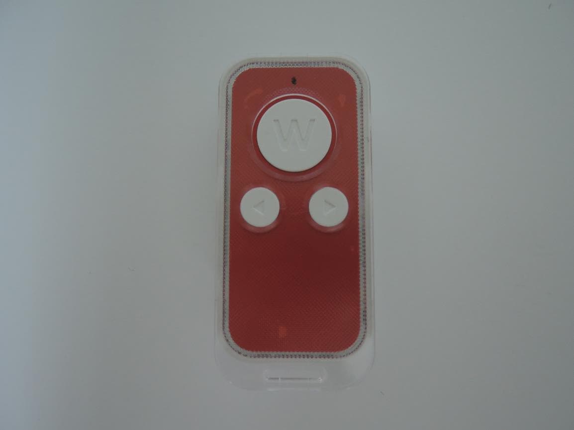
Click to zoom
Application Details
- Equipment Class
- DTS - Digital Transmission System
- Date of Grant
- Oct 12, 2014
- Application Purpose
- Original Equipment
- Date of Application
- Oct 12, 2014
- Equipment Note
- ESL Remote Controller
- Frequency Range
- 2405.00000000 - 2480.00000000
- Company
- Samsung Electro Mechanics
- Country
- South Korea
Documents & Files
Document Text
Text extracted from the exhibit documents filed with the FCC. Open a document above to read the original.
Cover Letter(s)
314 Maetan-3 Dong Pal Dal-Ku Kyungki-Do, Suwon-City, Korea, 442-743 Date: Sep. 16, 2014 Letter of Authorization We, the undersigned, hereby authorize Harvey Sung of DT&C Co., Ltd. to act on our behalf in all manners relating to application for equipment authorization for FCCID: E2X-RC including signing of all documents relating to these matters. Any and all acts carried out by Harvey Sung of DT&C Co., Ltd. on our behalf shall have the same affect as acts of our own. This authorization is valid until further written notice from Samsung Electro Mechanics “I, the undersigned, hereby certify that we are not subject to a denial of federal benefits, that includes FCC benefits, pursuant to Section 5301 of the Anti-Drug Abuse Act of 1988, 21 U.S.C. 853(a).” Sincerely, Jin Hwan, Lim Assistant Manager
Cover Letter(s)
DT&C Co., Ltd. 42, Yurim-ro, 154beon-gil, Cheoin-gu, Yongin-si, Gyeonggi-do, Korea 449-935 Date: Sep 16, 2014 UL Verification Services Inc. 47173 Benicia Street Fremont, CA 94538, USA To whom it may concern: I, the undersigned, hereby authorize Ms. Claire Hoque/Application Examiner of Compliance Engineering Services, Inc., d.b.a. Compliance Certification Services and hereafter referred to as CCS, to act on our behalf in all manners relating to application for equipment authorization, including signing of all documents relating to these matters. Any and all acts carried out by Ms. Claire Hoque of CCS on our behalf shall have the same effect as acts of our own. I, the undersigned, hereby certify that we are not subject to a denial of federal benefits, that includes FCC benefits, pursuant to Section 5301 of the Anti-Drug Abuse Act of 1988, 21 U.S.C. 853(a). In authorizing CCS as our agent, we still recognize that we are responsible to: a) comply with the relevant provisions of the certification program; b) make all necessary arrangements for the conduct of the evaluation, including provision for examining documentation and access to all areas, records (including internal audit reports) and personnel for the purposes of evaluation (e.g. testing, inspection, assessment, surveillance, reassessment) and resolution of complaints; c) make claims regarding certification only in respect of the scope for which certification has been granted; d) do not use our product certification in such a manner as to bring the Certification Division into disrepute and not make any statement regarding our product certification which the Certification Division may consider misleading or unauthorized; e) upon suspension or cancellation of certification, discontinue use of all advertising matter that contains any reference thereto and return any certification documents as required by the Certification Division; f) use certification only to indicate the products are certified as being in conformity with specified standards;
Cover Letter(s)
Samsung Electro Mechanics 314, Maethan-3 Dong, Paldal-Ku, Kyungki-Do, Suwon-City, Korea, 442-743 Date: Sep 16, 2014 UL Verification Services Inc. 47173 Benicia Street Fremont, CA 94538, USA RE: Request of Confidentiality for FCCID: E2X-RC To Whom It may Concern: Pursuant to Sections 0.457 and 0.459 of the Commission`s Rules(CFR 47), and Section 552 (b) (4) of the Freedom of Information Act, Samsung Electro Mechanics hereby requests confidentiality and treatment of certain information accompanying this application. The materials contain trade secrets and proprietary information not customarily released to the public. The public disclosure of these matters might be harmful to the Applicant and provide unjustified benefits to its competitors. We are also hereby request Short-Term Confidentiality for 180 days after the grant as outlined in Public Notice DA 04-1705. This provision will give Samsung Electro Mechanics temporary confidentiality of commercially sensitive information prior to product release. The requested permanent and Short-Term Confidential exhibits are listed as follows: PERMANENT & SHORT-TERM CONFIDENTIAL LIST Exhibit Description PERMANENT 1 Block Diagram 2 Schematics 3 Part Lists 4 Operation Description SHORT-TERM 5 Internal Photos 6 External Photos 7 Test-Setup Photos 8 User Manual The Applicant understands that pursuant to Rule 0.457, disclosure of this application and all accompanying documentations, where applicable, will not be public before the date of the Grant for this application. Sincerely, Jin Hwan, Lim Manager
External Photos
FCCID: E2X-RC Copyright Ⓒ 2014, DT&C Co., Ltd. View 1 FCCID: E2X-RC Copyright Ⓒ 2014, DT&C Co., Ltd. View 2 FCCID: E2X-RC Copyright Ⓒ 2014, DT&C Co., Ltd. View 3
ID Label/Location Info
FCC ID: E2X-RC Copyright Ⓒ 2014, DT&C Co., Ltd. FCC ID SAMPLE LABEL & LOCATION LABELLING REQUIREMENTS PER §2.925 The Label shown shall be permanently affixed at a conspicuous location on the device and be readily visible to the user at the time of purchase - The FCC label shown is representative of the label that will appear on the radio when in production. Other information may also be included in the user manual.
Internal Photos
FCCID: E2X-RC Copyright Ⓒ 2014, DT&C Co., Ltd. Page 1 / 3 View 1 FCCID: E2X-RC Copyright Ⓒ 2014, DT&C Co., Ltd. Page 2 / 3 View 2 FCCID: E2X-RC Copyright Ⓒ 2014, DT&C Co., Ltd. Page 3 / 3 View 3
RF Exposure Info
Portable device Movile device MHzmm = dBi = [ ( 8mW / 5mm ) ] X [ √2.48GHz ] = 2.5 - Max. transmitting frequency = 9.00 dBm dBm [ ( max. power of channel, including tune-up tolerance, mW ) / ( min. test separation distance, mm ) ] · [ √f(GHz) ] ≤ 3.0 for 1g SAR and ≤ 7.5 for 10g extremity SAR September 23, 2014 FCC ID : E2X-RC KDB 447498 D01 clasue 4.3.1 Step 1) SAR test exclusion thresho lds for 100MHz to 6GHz at test separationn distances ≤ 50 mm - Device category = Standalone SAR test exclusion considerations 0 - Max. power with turn-up tolerance = 8.0 2480 - Min. test separ ation distance = mW 9.00 - Max. Antenna Gain = 1.7 Max. Typical Power = Note. The calculation result was rounded to one decimal place f or comparison. → SAR evaluation for general population exposure conditions by measurement or numerical simulation is not required. Copyright ⓒ 2014, DT&C Co., Ltd.
Test Report
FCCID: E2X-RC DEMC1405-02052 Report No.: DRTFCC1409-1201 TRF-RF226(00)140710 Page 2 / 30 Copyright ○ C 2014, DT&C Co., Ltd. Test Report Version Test Report No. Date Description DRTFCC1409-1201 Sep. 22, 2014 Initial issue FCCID: E2X-RC DEMC1405-02052 Report No.: DRTFCC1409-1201 TRF-RF226(00)140710 Page 3 / 30 Copyright ○ C 2014, DT&C Co., Ltd. Table of Contents 1. EUT DESCRIPTION .................................................................... 4 2. SUMMARY OF TESTS ................................................................ 5 3. TEST METHODOLOGY .............................................................. 6 3.1 EUT Configuration .............................................................................................. 6 3.2 EUT Exercise ...................................................................................................... 6 3.3 General Test Procedures ................................................................................... 6 3.4 Description of Test Modes ................................................................................ 6 4. INSTRUMENT CALIBRATION .................................................... 7 5. FACILITIES AND ACCREDITATIONS ........................................ 7 5.1 Facilities .............................................................................................................. 7 5.2 Equipment ........................................................................................................... 7 6. ANTENNA REQUIREMENTS ..................................................... 7 7. TEST RESULT ............................................................................ 8 7.1 6dB Bandwidth ................................................................................................... 8 7.2 Maximum Peak Conducted Output Power ..................................................... 11 7.3 Maximum Power Spectral Density. ................................................................. 14 7.4 Out of Band Emissions in non-restricted frequency band ........................... 17 7.5 Out of Band Emissions in restricted frequency band .................................. 24 7.6 AC Power-line Conducted Emissions ............................................................ 27 7.7 Occupied Bandwidth ........................................................................................ 28 8. LIST OF TEST EQUIPMENT ..................................................... 29 APPENDIX I................................................................................... 30 FCCID: E2X-RC DEMC1405-02052 Report No.: DRTFCC1409-1201 TRF-RF226(00)140710 Page 4 / 30 Copyright ○ C 2014, DT&C Co., Ltd. 1. EUT DESCRIPTION Product ESL Remote Controller Model Name SLT-RC004 Power Supply DC 3.0V(Lithium Ion Battery) Frequency Range 2405 ~ 2480MHz(16 channels) Modulation Type OQPSK(ZIGBEE) Antenna Specification Antenna Type: InternalAntenna Antenna Gain: 1.70 dBi(PK) FCCID: E2X-RC DEMC1405-02052 Report No.: DRTFCC1409-1201 TRF-RF226(00)140710 Page 5 / 30 Copyright ○ C 2014, DT&C Co., Ltd. 2. SUMMARY OF TESTS FCC Part Section(s) RSS Section(s) Parameter Limit Test Condition Status Note 1 I. Transmitter Mode (TX) 15.247(a) RSS-210 [A8.2] 6 dB Bandwidth > 500 kHz Conducted C 15.247(b) RSS-210 [A8.4] Transmitter Output Power < 1Watt C 15.247(d) RSS-210 [A8.5] Out of Band Emissions / Band Edge 20dBc in any 100kHz BW C 15.247(e) RSS-210 [A8.2] Transmitter Power Spectral Density < 8dBm / 3kHz C - RSS Gen [4.6.1] Occupied Bandwidth (99%) RSS-Gen(4.6.1) NA 15.205 15.209 RSS-210 [A8.5] General Field Strength Limits (Restricted Bands and Radiated Emission Limits) <FCC 15.209 limits Radiated C Note2 15.207 RSS-Gen [7.2.4] AC Conducted Emissions < FCC 15.207 limits AC Line Conducted NA Note3 15.203 - Antenna Requirements FCC 15.203 - C Note 1: C=Comply NC=Not Comply NT=Not Tested NA=Not Applicable Note 2: This test item was performed in each axis and the worst case data was reported. Note 3: The power of this device is only DC(Not rechargeable Battery). FCCID: E2X-RC DEMC1405-02052 Report No.: DRTFCC1409-1201 TRF-RF226(00)140710 Page 6 / 30 Copyright ○ C 2014, DT&C Co., Ltd. 3. TEST METHODOLOGY Generally the tests were performed according to the KDB558074 v03r02. And ANSI C63.10-2009 was used to reference appropriate EUT setup and maximizing procedures of radiated spurious emission and AC line conducted emission testing. 3.1 EUT Configuration The EUT configuration for testing is installed on RF field strength measurement to meet theCommissions requirement and operating in a manner that intends to maximize its emissioncharacteristics in a continuous normal application. 3.2 EUT Exercise The EUT was operated in the engineering mode to fix the TX frequency that was for the purpose ofthe measurements. According to its specifications, the EUT must comply with the requirements ofthe Section 15.207, 15.209 and 15.247 under the FCC Rules Part 15 Subpart C. 3.3 General Test Procedures Conducted Emissions According to therequirements in Section 6.2 of ANSI C63.10, the EUT is placed on the turntable, which is 0.8 m above ground plane and the conducted emissions from theEUT are measured in the frequency range between 0.15 MHz and 30MHz using CISPR Quasi-peakand Average detector. Radiated Emissions The EUT is placed on a turntable, which is 0.8 m above ground plane. The turntable shall rotate360 degrees to determine the position of maximum emission level. EUT is set 3 m away from thereceiving antenna, which varied from 1 m to 4 m to find out the highest emission. And also, eachemission was to be maximized by changing the polarization of receiving antenna both horizontaland vertical. In order to find out the highest emission, the relative positions of this hand-heldtransmitter (EUT) was rotated through three orthogonal axis according to the requirements inSection6.3 of ANSI C63.10 3.4 Description of Test Modes The EUT has been tested withthe operating condition for max…
Text truncated - open the document above for the full version.
Test Setup Photos
FCC ID: E2X-RC Copyright Ⓒ 2014, DT&C Co., Ltd. Test Setup Photo of Radiated Measurement
Contact Information
Applicant
Jinhwan Lim(Assistant Manager)
Test Firm
DT&C Co.,Changho Lee
Technical Specifications
| # | Rule Parts | Frequency Range | Power Output |
|---|---|---|---|
| 1 | 15C | 2.40 GHz - 2.48 GHz | 8.00 mW |
Other Applications from Samsung Electro Mechanics

E2X-ST-GR2900N
Oct 01, 2015ESL Graphic TAG
Equipment Class
DTS - Digital Transmission System
E2X-ST-GM29XXF
Sep 23, 2015ESL Graphic TAG
Equipment Class
DTS - Digital Transmission System
E2X-ST-GM22XXF
Sep 16, 2015ESL Graphic TAG
Equipment Class
DTS - Digital Transmission System
E2X-ST-GM42003N
Sep 10, 2015ESL Graphic TAG
Equipment Class
DTS - Digital Transmission System
E2X-ST-GM6000N
Aug 26, 2015ESL Graphic TAG
Equipment Class
DTS - Digital Transmission System