E2X-ST-GM16XX1ESL Graphic TAG
Samsung Electro Mechanics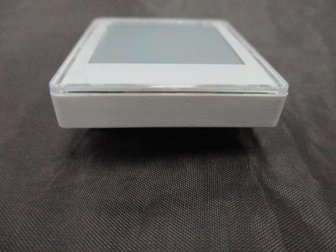
Click to zoom
Application Details
- Equipment Class
- DTS - Digital Transmission System
- Date of Grant
- Nov 13, 2014
- Application Purpose
- Original Equipment
- Date of Application
- Nov 13, 2014
- Equipment Note
- ESL Graphic TAG
- Frequency Range
- 2405.00000000 - 2480.00000000
- Company
- Samsung Electro Mechanics
- Country
- South Korea
Documents & Files
Document Text
Text extracted from the exhibit documents filed with the FCC. Open a document above to read the original.
Users Manual
1. General Outline 1.1 Overview S-Label EPD-TAG is the product for RF transmission solution ideal for ZigBee and other low cost, low power IEEE 802.15.4 RF transmission applications. S-Label EPD- TAG consists of RF Transceiver, RF circuitry and 8051- compatible MCU offering ZigBee network protocol and 802.15.4 MAC protocol and other peripheral devices. 1.2 Features · Display : EPD PANEL ( Graphic type) · Communication : Wireless communication based on IEEE 802.15.4 · Operating on 2.4 GHz Unlicensed ISM band for ZigBee · Low Power Consumption · External Wakeup : RF Wakeup(using ISM Band(2.4GHz)) · Outline Dimension : 37 mm x 44.9 mm x 13.9 mm · Active Area : 27.6 x 27.6 mm · No additional anti - theft locking structure : Rail Mounted only · RoHS compliant 1.3 Application · Retail industry with the electronic display and platform, solutions, and services · Intelligently communicating, managing, and optimizing price and product informations. 1.4 Physical Dimension ( mm) 1.5 Exploded View of EPD TAG 2. Specifications 2.1 Product ItemDescription Size 37 x 44.9 x 13.9 mm Battery CR2477 Lithium Battery (3 V, 1 ea) 2.4 ~ 3.3 Vdc(condtion : In active status) DisplayEPD PANEL display ( Graphic type) Information displayPrice, Unit, Discount, etc. Communication IEEE802.15.4 2.4 GHz ISM Band (2405 MHz~2480MHz) DistanceRadius 20m ( Indoor, Line of Sight) Operation Temp. 5 ~ 40 °C Etc.No additional anti-theft locking structure : Rail Mounted only 2.2 Radio ( RF) 2.2.1 R&D Characteristic & OQC ItemsParameter spec. UnitsCondition Min Typ Max TX Transmit Power -5 0 5 d Bm Error Vector Magnitude 10 30 % When measured for 100 chips Tx Current - 40 mA Total current at max Tx Power RXReceiver Sensitivity -90 -- dBmPER < 1% 2.2.2 Production Characteristic ItemsParameter spec. UnitsCondition Min Typ Max TX Transmit Power -3 0 5 dBm Error Vector Magnitude 10 28 % When measured for 100 chips Tx Current - 37 mA Total current at max Tx Power RXReceiver Sensitivity -90 -- dBmPER < 1% * Test Channel : 2480 MHz ( RX Test Channel can be changed according to the environment) * The contents in the grayed cells are not necessary to manage by Cpk. 2.3MAC Label drawing & example ( Front, Back) · Product information is indicated in a printed sticker label. The information consists of MODEL(model name), MFD(manufacturing date), S/N(serial number), MAC(MAC address), CE certification mark, and Manufacturer(SEMCO). 1) Model Name : ST-GM16XX1 2) MFD : ( month).(date).(year) ex) SEP.25.2013 3) S/N : numeric & barcode & barcode number(hexadecimal 10 digit) 4) MAC : barcode & barcode number(hexadecimal 16 digit) - 6 digits(1st ~ 6 th) : xxxxxx ( Company code) - 6 digits(7th ~ 12 th) : xxxxxx ( Increasing number : 000000 ~ FFFFFF) - 4 digits(13th ~ 16 th) : 1601 3. Package Specifications 4 Cautions for Treatment Provisions should be made to protect against any damage to the product caused by improper handling. It is highly recommended that the product should be installed within 3 months from the date of arrival in the logistics hub. Recommended storage condition is in 5-40 Celsius degree, 20-60% RH environment. This RF device operates on the 2.4 GHz frequency band and can produce radio interference. The device, therefore, may not be used for applications where safety of human lives is concerned. 4.1 Usage Environment Take extra cautions when using this RF device in the vicinity of other electronic devices and appliances. Most electronic devices and appliances use electromagnetic waves. Electromagnetic waves emitted by this RF device can affect other electronic devices and appliances. If using the device in an explosion hazard area, follow all safety regulations, instructions, and signals. 4.2 Storage and Use - Moisture and liquids can damage internal parts and circuit boards if allowed to enter into the device itself. - Do not place or store the product on a sloped surface. The product may slide and fall off the surface and damaged. - Use the product in temperatures ranging from +5 °C to +40 °C . Parts and circuits may be damaged if used or stored under temperature extremes. - The display panel needs extra care when handling. - Do not apply any impacts on outside since e-Paper display is fragile. - Continuous exposure to excessive moisture ( over 60% RH) or UV makes display lifetime shortened. - Ghosting image may be appeared in temperature conditions of less than 15 Celsius degree. - Avoid areas with strong magnetism or subject to magnetism. Contact between the device and a magnetic object can lead to malfunctions. - Do not place the product near heat-producing kitchen appliances like a stove or a microwave or in the vicinity of highly pressurized containers. - External impact to the product, such as from being dropped, can damage the product. - Twisting and bending the product can damage the exterior casing and the internal components. - If this product operates abnormally in eliminating battery vinyl or replacing battery, you should discharge it by contacting battery terminal (+) and (-). - This product uses 2.4 GHz frequency band for wireless communication network. Radio communications can be limited or affected by other applications which share same frequency band, such as WiFi, Bluetooth, Zigbee, etc. - Frequent communications, updates and screen renewals may reduce battery life time. WARNING : This equipment may generate or use radio frequency energy. Changes or modifications to this equipment may cause harmful interference unless the modifications are expressly approved in the instruction manual. The user could lose the authority to operate this equipment if an unauthorized change or modification is made. This device complies with part 15 of the FCC Rules. Operation is subject to the following two conditions: (1) This device may not cause harmful interference, and (2) this device must accept any interference received, Including interference that may cause undesired operation. NOT E : This equipment has been tested and found t…
Text truncated - open the document above for the full version.
Cover Letter(s)
314 Maetan-3 Dong Pal Dal-Ku Kyungki-Do, Suwon-City, Korea, 442-743 Date: Oct. 31, 2014 Letter of Authorization We, the undersigned, hereby authorize Harvey Sung of DT&C Co., Ltd. to act on our behalf in all manners relating to application for equipment authorization for FCCID: E2X-ST-GM16XX1 including signing of all documents relating to these matters. Any and all acts carried out by Harvey Sung of DT&C Co., Ltd. on our behalf shall have the same affect as acts of our own. This authorization is valid until further written notice from Samsung Electro Mechanics “I, the undersigned, hereby certify that we are not subject to a denial of federal benefits, that includes FCC benefits, pursuant to Section 5301 of the Anti-Drug Abuse Act of 1988, 21 U.S.C. 853(a).” Sincerely, Jin Hwan, Lim Assistant Manager
Cover Letter(s)
DT&C Co., Ltd. 42, Yurim-ro, 154beon-gil, Cheoin-gu, Yongin-si, Gyeonggi-do, Korea 449-935 Date: Oct. 31, 2014 UL Verification Services Inc. 47173 Benicia Street Fremont, CA 94538, USA To whom it may concern: I, the undersigned, hereby authorize Ms. Claire Hoque/Application Examiner of Compliance Engineering Services, Inc., d.b.a. Compliance Certification Services and hereafter referred to as CCS, to act on our behalf in all manners relating to application for equipment authorization, including signing of all documents relating to these matters. Any and all acts carried out by Ms. Claire Hoque of CCS on our behalf shall have the same effect as acts of our own. I, the undersigned, hereby certify that we are not subject to a denial of federal benefits, that includes FCC benefits, pursuant to Section 5301 of the Anti-Drug Abuse Act of 1988, 21 U.S.C. 853(a). In authorizing CCS as our agent, we still recognize that we are responsible to: a) comply with the relevant provisions of the certification program; b) make all necessary arrangements for the conduct of the evaluation, including provision for examining documentation and access to all areas, records (including internal audit reports) and personnel for the purposes of evaluation (e.g. testing, inspection, assessment, surveillance, reassessment) and resolution of complaints; c) make claims regarding certification only in respect of the scope for which certification has been granted; d) do not use our product certification in such a manner as to bring the Certification Division into disrepute and not make any statement regarding our product certification which the Certification Division may consider misleading or unauthorized; e) upon suspension or cancellation of certification, discontinue use of all advertising matter that contains any reference thereto and return any certification documents as required by the Certification Division; f) use certification only to indicate the products are certified as being in conformity with specified standards;
Cover Letter(s)
Samsung Electro Mechanics 314, Maethan-3 Dong, Paldal-Ku, Kyungki-Do, Suwon-City, Korea, 442-743 Date: Oct. 31, 2014 UL Verification Services Inc. 47173 Benicia Street Fremont, CA 94538, USA RE: Request of Confidentiality for FCCID: E2X-ST-GM16XX1 To Whom It may Concern: Pursuant to Sections 0.457 and 0.459 of the Commission`s Rules(CFR 47), and Section 552 (b) (4) of the Freedom of Information Act, Samsung Electro Mechanics hereby requests confidentiality and treatment of certain information accompanying this application. The materials contain trade secrets and proprietary information not customarily released to the public. The public disclosure of these matters might be harmful to the Applicant and provide unjustified benefits to its competitors. We are also hereby request Short-Term Confidentiality for 180 days after the grant as outlined in Public Notice DA 04-1705. This provision will give Samsung Electro Mechanics temporary confidentiality of commercially sensitive information prior to product release. The requested permanent and Short-Term Confidential exhibits are listed as follows: PERMANENT & SHORT-TERM CONFIDENTIAL LIST Exhibit Description PERMANENT 1 Block Diagram 2 Schematics 3 Part Lists 4 Operation Description SHORT-TERM 5 Internal Photos 6 External Photos 7 Test-Setup Photos 8 User Manual The Applicant understands that pursuant to Rule 0.457, disclosure of this application and all accompanying documentations, where applicable, will not be public before the date of the Grant for this application. Sincerely, Jin Hwan, Lim Manager
Cover Letter(s)
SAMSUNG ELECTRO-MECHANICS 314,Metan 3-dong,Yeongtong-gu,Suwon-si,Gyeonggi-do 443-743,Korea 2014.10.22 DT&C Co.,Ltd. DECLARATION OF IDNTITY Manufacturer : SAMSUNG ELECTRO-MECHANICS Type of Product : ESL Graphic TAG Model Name : ST-GM16XX1 FCC ID : E2X-ST-GM16XX1 We hereby declare that Before After ST-GM16XX1 ST-GM16XX1 ST-GM16KC1 the color of case is 2 type(White color = ST-GM16XX1 & Black color = ST-GM16KC1). ST-GM16XX1 ST-GM16KC1 Sincerely, Dong-sik Yoon (Principal Engineer)
External Photos
FCCID: E2X-ST-GM16XX1 Copyright Ⓒ 2014, DT&C Co., Ltd. View 1 FCCID: E2X-ST-GM16XX1 Copyright Ⓒ 2014, DT&C Co., Ltd. View 2 FCCID: E2X-ST-GM16XX1 Copyright Ⓒ 2014, DT&C Co., Ltd. View 3
ID Label/Location Info
FCC ID : E2X-ST-GM16XX1 Copyright Ⓒ 2014, DT&C Co., Ltd. FCC ID SAMPLE LABEL & LOCATION LABELLING REQUIREMENTS PER §2.925 The Label shown shall be permanently affixed at a conspicuous location on the battery cover of the device and be readily visible to the user at the time of purchase. If the battery cover is removed, this device does not work. - The FCC label shown is representative of the label that will appear on the radio when in production. Other information may also be included in the user manual.
Internal Photos
FCCID: E2X-ST-GM16XX1 Copyright Ⓒ 2014, DT&C Co., Ltd. Page1 / 3 View 1 FCCID: E2X-ST-GM16XX1 Copyright Ⓒ 2014, DT&C Co., Ltd. Page2 / 3 View 2 FCCID: E2X-ST-GM16XX1 Copyright Ⓒ 2014, DT&C Co., Ltd. Page3 / 3 View 3
Parts List/Tune Up Info
Portable device Movile device MHzmm = dBi = [ ( 3.2mW / 5mm ) ] X [ √2.48GHz ] = 1 Note. The calculation result was rounded to one decimal place f or comparison. - Max. transmitting frequency = 5.00 dBm dBm [ ( max. power of channel, including tune-up tolerance, mW ) / ( min. test separation distance, mm ) ] · [ √f(GHz) ] ≤ 3.0 for 1g SAR and ≤ 7.5 for 10g extremity SAR November 11, 2014 FCC ID : E2X-ST-GM16XX1 KDB 447498 D01 clasue 4.3.1 Step 1) SAR test exclusion thresho lds for 100MHz to 6GHz at test separationn distances ≤ 50 mm - Device category = Standalone SAR test exclusion considerations 0 - Max. power with turn-up tolerance = 3.2 2480 - Min. test separ ation distance = mW 5.00 - Max. Antenna Gain = -3.7 Max. Typical Power = → SAR evaluation for general population exposure conditions by measurement or numerical simulation is not required. Copyright ⓒ 2014 DT&C Co Ltd Copyright ⓒ 2014 , DT&C Co ., Ltd .
Test Report
FCCID: E2X-ST-GM16XX1 DTNC1409-04032 Report No.: DRTFCC1411-1422 TRF-RF226(00)140710 Page 2 / 30 Copyright ○ C 2014, DT&C Co., Ltd. Test Report Version Test Report No. Date Description DRTFCC1411-1422 Nov. 11, 2014 Initial issue FCCID: E2X-ST-GM16XX1 DTNC1409-04032 Report No.: DRTFCC1411-1422 TRF-RF226(00)140710 Page 3 / 30 Copyright ○ C 2014, DT&C Co., Ltd. Table of Contents 1. EUT DESCRIPTION .................................................................... 4 2. SUMMARY OF TESTS ................................................................ 5 3. TEST METHODOLOGY .............................................................. 6 3.1 EUT Configuration .............................................................................................. 6 3.2 EUT Exercise ...................................................................................................... 6 3.3 General Test Procedures ................................................................................... 6 3.4 Description of Test Modes ................................................................................ 6 4. INSTRUMENT CALIBRATION .................................................... 7 5. FACILITIES AND ACCREDITATIONS ........................................ 7 5.1 Facilities .............................................................................................................. 7 5.2 Equipment ........................................................................................................... 7 6. ANTENNA REQUIREMENTS ..................................................... 7 7. TEST RESULT ............................................................................ 8 7.1 6dB Bandwidth ................................................................................................... 8 7.2 Maximum Peak Conducted Output Power ..................................................... 11 7.3 Maximum Power Spectral Density. ................................................................. 14 7.4 Out of Band Emissions in non-restricted frequency band ........................... 17 7.5 Out of Band Emissions in restricted frequency band .................................. 24 7.6 AC Power-line Conducted Emissions ............................................................ 27 7.7 Occupied Bandwidth ........................................................................................ 28 8. LIST OF TEST EQUIPMENT ..................................................... 29 APPENDIX I................................................................................... 30 FCCID: E2X-ST-GM16XX1 DTNC1409-04032 Report No.: DRTFCC1411-1422 TRF-RF226(00)140710 Page 4 / 30 Copyright ○ C 2014, DT&C Co., Ltd. 1. EUT DESCRIPTION Product ESL Graphic TAG Model Name ST-GM16XX1 Add Model Name ST-GM16KC1 Power Supply DC 3.0V(Lithium Ion Battery) Frequency Range 2405 ~ 2480MHz(16 channels) Modulation Type OQPSK(ZIGBEE) Antenna Specification Antenna Type: Internal Antenna Antenna Gain: -3.70 dBi(PK) FCCID: E2X-ST-GM16XX1 DTNC1409-04032 Report No.: DRTFCC1411-1422 TRF-RF226(00)140710 Page 5 / 30 Copyright ○ C 2014, DT&C Co., Ltd. 2. SUMMARY OF TESTS FCC Part Section(s) RSS Section(s) Parameter Limit Test Condition Status Note 1 I. Transmitter Mode (TX) 15.247(a) RSS-210 [A8.2] 6 dB Bandwidth > 500 kHz Conducted C 15.247(b) RSS-210 [A8.4] Transmitter Output Power < 1Watt C 15.247(d) RSS-210 [A8.5] Out of Band Emissions / Band Edge 20dBc in any 100kHz BW C 15.247(e) RSS-210 [A8.2] Transmitter Power Spectral Density < 8dBm / 3kHz C - RSS Gen [4.6.1] Occupied Bandwidth (99%) RSS-Gen(4.6.1) NA 15.205 15.209 RSS-210 [A8.5] General Field Strength Limits (Restricted Bands and Radiated Emission Limits) < FCC 15.209 limits Radiated C Note2 15.207 RSS-Gen [7.2.4] AC Conducted Emissions < FCC 15.207 limits AC Line Conducted NA Note3 15.203 - Antenna Requirements FCC 15.203 - C Note 1: C=Comply NC=Not Comply NT=Not Tested NA=Not Applicable Note 2: This test item was performed in each axis and the worst case data was reported. Note 3: The power of this device is only DC(Not rechargeable Battery). FCCID: E2X-ST-GM16XX1 DTNC1409-04032 Report No.: DRTFCC1411-1422 TRF-RF226(00)140710 Page 6 / 30 Copyright ○ C 2014, DT&C Co., Ltd. 3. TEST METHODOLOGY Generally the tests were performed according to the KDB558074 v03r02. And ANSI C63.10-2009 was used to reference appropriate EUT setup and maximizing procedures of radiated spurious emission and AC line conducted emission testing. 3.1 EUT Configuration The EUT configuration for testing is installed on RF field strength measurement to meet the Commissions requirement and operating in a manner that intends to maximize its emission characteristics in a continuous normal application. 3.2 EUT Exercise The EUT was operated in the engineering mode to fix the TX frequency that was for the purpose of the measurements. According to its specifications, the EUT must comply with the requirements of the Section 15.207, 15.209 and 15.247 under the FCC Rules Part 15 Subpart C. 3.3 General Test Procedures Conducted Emissions According to the requirements in Section 6.2 of ANSI C63.10, the EUT is placed on the turntable, which is 0.8 m above ground plane and the conducted emissions from the EUT are measured in the frequency range between 0.15 MHz and 30MHz using CISPR Quasi-peak and Average detector. Radiated Emissions The EUT is placed on a turntable, which is 0.8 m above ground plane. The turntable shall rotate360 degrees to determine the position of maximum emission level. EUT is set 3 m away from the receiving antenna, which varied from 1 m to 4 m to find out the highest emission. And also, each emission was to be maximized by changing the polarization of receiving antenna both horizontal and vertical. In order to find out the highest emission, the relative positions of this hand-held transmitter (EUT) was rotated through three orthogonal axis according to the requirements in Section6.3 of ANSI C63.10 3.4 Descripti…
Text truncated - open the document above for the full version.
Test Setup Photos
FCC ID: E2X-ST-GM16XX1 Copyright Ⓒ 2014, DT&C Co., Ltd. Test Setup photographs EUT Position: X-axis EUT Position: Y-axis EUT Position: Z-axis FCC ID: E2X-ST-GM16XX1 Copyright Ⓒ 2014, DT&C Co., Ltd. Test Setup Photo of Radiated Measurement (0.009 ~ 30MHz) FCC ID: E2X-ST-GM16XX1 Copyright Ⓒ 2014, DT&C Co., Ltd. Test Setup Photo of Radiated Measurement (below 1000MHz) FCC ID: E2X-ST-GM16XX1 Copyright Ⓒ 2014, DT&C Co., Ltd. Test Setup Photo of Radiated Measurement (Above 1GHz)
Contact Information
Applicant
Jinhwan Lim(Assistant Manager)
Test Firm
DT&C Co., Ltd.WonJung Lee
Technical Specifications
| # | Rule Parts | Frequency Range | Power Output |
|---|---|---|---|
| 1 | 15C | 2.40 GHz - 2.48 GHz | 2.00 mW |
Other Applications from Samsung Electro Mechanics

E2X-ST-GR2900N
Oct 01, 2015ESL Graphic TAG
Equipment Class
DTS - Digital Transmission System
E2X-ST-GM29XXF
Sep 23, 2015ESL Graphic TAG
Equipment Class
DTS - Digital Transmission System
E2X-ST-GM22XXF
Sep 16, 2015ESL Graphic TAG
Equipment Class
DTS - Digital Transmission System
E2X-ST-GM42003N
Sep 10, 2015ESL Graphic TAG
Equipment Class
DTS - Digital Transmission System
E2X-ST-GM6000N
Aug 26, 2015ESL Graphic TAG
Equipment Class
DTS - Digital Transmission System