E2XSWL-2210PWLAN PCI Card
Samsung Electro Mechanics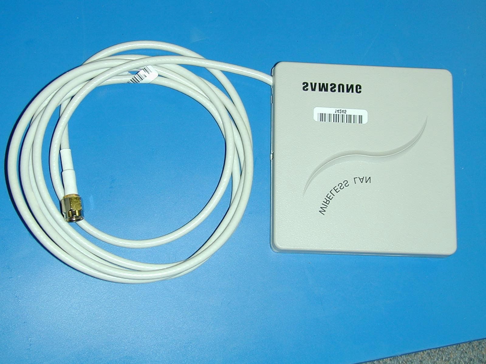
Click to zoom
Application Details
- Equipment Class
- DSS - Part 15 Spread Spectrum Transmitter
- Date of Grant
- Sep 02, 2002
- Application Purpose
- Original Equipment
- Date of Application
- Sep 02, 2002
- Equipment Note
- WLAN PCI Card
- Frequency Range
- 2412.00000000 - 2462.00000000
- Company
- Samsung Electro Mechanics
- Country
- South Korea
Documents & Files
Document Text
Text extracted from the exhibit documents filed with the FCC. Open a document above to read the original.
Users Manual
Rhein Tech Laboratories Report number: 2002120 360 Herndon Parkway FCC: Part 15.247 Suite 1400 Industry Canada: RSS-210 FCC ID: E2XSWL-2210P Herndon, VA 20170 http://www.rheintech.com M/N: SWL-2210P Page 45 of 61 APPENDIX J: MANUAL Please see the following pages. 1 SAMSUNG MagicLAN SWL-2210M/P User Manual (Rev. 1.4) 2 Table of Contents 1. MagicLAN Installation ................................................................................9 1.1 Introduction ........................................................................................9 1.2 Technical Background ..........................................................................9 1.3 MagicLAN Overview............................................................................11 2. Before the Installation ...............................................................................13 2.1 What is in your Package ......................................................................13 2.2 System Requirement ...........................................................................13 2.3 Preparations For Installation..................................................................13 3. MagicLAN Installation for Windows 98/ME/NT4.0/2000/XP/Linux ................14 3.1 Installation Overview ..........................................................................14 3.2 Installation Procedure of Windows 98 ..............................................14 3.3 Installation Procedure of Windows ME ..............................................21 3.4 Installation Procedure of Windows NT4.0 ............................................. 27 3.5 Installation Procedure of Windows 2000 ...........................................36 3.6 Installation Procedure of Windows XP ..............................................42 3.7 Installation Procedure of Linux ...........................................................48 3.8 Update of MagicLAN Wireless LAN Card Driver........................................54 3.9 Removal of MagicLAN Wireless LAN Card Driver.........................54 4. The Program for setting MagicLAN................................................................56 4.1 The concept of Profile.........................................................................56 4.2 Installation Procedure....................................................................56 5. The main configuration of Program.................................................................61 5.1 Profile.............................................................................................63 5.1.1 The ‘New’ button......................................................................63 5.1.2 The ‘Apply’ button....................................................................63 5.1.3 The ‘Edit’ button......................................................................63 5.1.4 The ‘Delete’ button....................................................................66 5.2 Status..............................................................................................66 5.2.1 The ‘Current Status’ button..........................................................67 5.2.2 The ‘AP Status’ button...............................................................67 3 5.2.3 The ‘Site Survey’ button............................................................68 5.2.4 Statistics.................................................................................69 5.3 General Settings...................................................................................69 5.3.1 The ‘DHCP’ button.................................................................69 5.3.2 The ‘Options’ button................................................................70 5.4 Version........................................................................................70 6. Troubleshooting ....................................................................................72 Probable Symptoms and their Diagnosis................................................ 4 Notice 1 This manual cannot be reproduced in any form without the prior written permission of SAMSUNG Electro-Mechanics Co., Ltd. SAMSUNG Electro-Mechanics Co., Ltd. reserves the right to change this manual and the spec ifications to improve products without prior notice. You can get the most recent software and user documentation for all MagicLAN products on our web site. All other brand and product names are trademarks of registered trademarks of their respective holders. http://www.MagicLAN.com Service Dept . Young-sik Lyu ([email protected] ) Tel : +82-31-218-2416 Fax : +82-31-218-2413 Sales America Eun-Sung Cho([email protected]) Tel : +82-31-218-2407 Fax : +82-31-218-2414 Europe Yong-Il Kim ([email protected]) Tel : +82-31-218-2408 Fax : +82-31-218-2414 Asia Seong-Mun Jeong ([email protected] ) Tel : +82-31-218-2412 Fax : +82-31-218-2414 Copyright 1999 - 2002 SAMSUNG Electro-Mechanics Co., Ltd. All rights reserved. This is a generic manual; references to other products are contained herein. Note: This equipment has been tested and found to comply with the limits for a Class B digital device, pursuant to part 15 of the FCC Rules. these limits are designed to provide reasonable protection against harmful interference in a residential installation. This equipment generates, uses and can radiate radio frequency energy and, if not installed and used in accordance with the instructions, may cause harmful interference to radio communications. However, there is no guarantee that interference will not occur in a particular installation. If this equipment does cause harmful inter- ference to radio or television reception, which can be determined by turning the equipment off and on, the user is encouraged to try to correct the interference by one or more of the following measures: - Reorient or relocate the receiving antenna. - Increase the separation between the equipment and receiver. - Connect the equipment into an o…
Text truncated - open the document above for the full version.
Cover Letter(s)
American Telecommunications Certification Body Inc. 6731 Whittier Ave, McLean, VA 22101 August 29, 2002 RE: Samsung FCC ID: E2XSWL-2210P I have a few comments on this Application. 1.) The requested Pout is 33.9mW, but the Manual indicates a typical Pout of 50mW, approximately +1.7dB higher. Please resubmit all data at 50mW or justify. Response: The manual was incorrect; please see the revised manual that was uploaded with this response. 2.) Please confirm that this equipment as sold in US cannot be tuned to frequencies outside of 2400-2483.5MHz. Response: As sold in the US, this equipment cannot be tuned to frequencies outside of 2400- 2483.5MHz. Please see the revised manual uploaded with this response. 3.) Internal Photos, External Photos, and Label Location photos are of unacceptable quality. Please re-shoot and eliminate hot spots resulting from the flash, and all graininess. Response: Photos were retaken and were uploaded with this response. 4.) Please re-segregate the Internal Photos and External Photos. All views of the card and antenna before any disassembly should be considered an External Photo. Any view showing disassembly including removal of subassemblies should be considered an Internal View. Response: I apologize for the inconvenience. The photos have been properly segregated and were uploaded with this response. 5.) Please provide further justification of why the Operational Description should be held Confidential. This document does not appear to have sufficient detail to justify Confidential status. Please remember to change Confidentiality Request letter as required. Response: Please see the revised Confidentiality Request letter uploaded with this response. 6.) FYI: Band Edge Plots 3.1 to 3.4 are much more difficult to read than Modulated Bandwidth Plots in Section 7. For consistency and readability, in the future please choose the ploting techniques used in Section 7. Response: Noted. 7.) FYI: The boxed warning on pp. 5 of Manual is only marginally acceptable – the grammar is such that it can be open to interpretation. You may wish to advise your client to re-phrase the third and forth sentences. Response: Thank you for this comment, I will advise client. 8.) Your 731 form requests the use of DTS. Please show how this equipment fits the description of DTS and not DSS. Response: We request that this application be accepted as a DSS, not a DTS. William H. Graff President and Examining Engineer mailto: [email protected] The items indicated above must be submitted before processing can continue on the above referenced application. Failure to provide the requested information may result in application termination. Correspondence should be considered part of the permanent submission and may be viewed from the Internet after a Grant of Equipment Authorization is issued. Please do not respond to this correspondence using the email reply button. In order for your response to be processed expeditiously, you must submit your documents through the AmericanTCB.com website. Also, please note that partial responses increase processing time and should not be submitted. Any questions about the content of this correspondence should be directed to the sender.
Cover Letter(s)
Rhein Tech Laboratories Report number: 2002120 360 Herndon Parkway FCC: Part 15.247 Suite 1400 Industry Canada: RSS-210 FCC ID: E2XSWL-2210P Herndon, VA 20170 http://www.rheintech.com M/N: SWL-2210P Page 37 of 61 APPENDIX C: AGENCY AUTHORIZATION LETTER Please see the following page. September 22, 2000 American Telecommunications Certification Body, Inc. 6731 Whittier Avenue Suite C110 McLean, VA 22101 To Whom It May Concern: Please be advised that Samsung Electro-Mechanics authorizes Rhein Tech Laboratories, Inc. to act on our behalf, until otherwise notified, for applications submitted to American Telecommunications Certification Body, Inc. (ATCB). We certify that we are not subject to denial of federal benefits, that includes FCC benefits, pursuant to Section 5301 of the Anti-Drug Abuse ACT of 1988, U.S.C. 862. Further, no party, as defined in 47 CFR 1.2002(b), to the application is subject to denial of federal benefits, that includes FCC benefits. Thank you for your attention to this matter.
Cover Letter(s)
Federal Communications Commission Equipment Authorization Branch 7435 Oakland Mills Rd. Columbia, MD 21406 USA Subject: FCC ID: E2XSWL-2210P APRIL 18, 2002 Gentlemen, Samsung Electro-Mechanics hereby requests that the following items be kept confidential under sections 0.457 and 0.459 of the CFR. If this information was to be made public record it would adversely affect the core business. I would like to request the following items be confidential: (1) Schematics (2) Block Diagram (3) Product Description Sincerely, John K. Seo Senior Manager Network Division, R&D Lab. 2 nd Wireless LAN ELECTRO-MECHANICS 31 4,Maetan 3- Dong, Paldal-ku, Suwoni, Kyung ki- Do,Kor ea,441- 743 T E L 82 -31 -2 10- 57 12 FAX 82- 31 -21 0- 552 9
Cover Letter(s)
American Telecommunications Certification Body Inc. 6731 Whittier Ave, McLean, VA 22101 August 29, 2002 RE: Samsung FCC ID: E2XSWL-2210P I have a few comments on this Application. 1.) The requested Pout is 33.9mW, but the Manual indicates a typical Pout of 50mW, approximately +1.7dB higher. Please resubmit all data at 50mW or justify. 2.) Please confirm that this equipment as sold in US cannot be tuned to frequencies outside of 2400-2483.5MHz. 3.) Internal Photos, External Photos, and Label Location photos are of unacceptable quality. Please re-shoot and eliminate hot spots resulting from the flash, and all graininess. 4.) Please re-segregate the Internal Photos and External Photos. All views of the card and antenna before any disassembly should be considered an External Photo. Any view showing disassembly including removal of subassemblies should be considered an Internal View. 5.) Please provide further justification of why the Operational Description should be held Confidential. This document does not appear to have sufficient detail to justify Confidential status. Please remember to change Confidentiality Request letter as required. 6.) FYI: Band Edge Plots 3.1 to 3.4 are much more difficult to read than Modulated Bandwidth Plots in Section 7. For consistency and readability, in the future please choose the ploting techniques used in Section 7. 7.) FYI: The boxed warning on pp. 5 of Manual is only marginally acceptable – the grammar is such that it can be open to interpretation. You may wish to advise your client to re-phrase the third and forth sentences. 8.) Your 731 form requests the use of DTS. Please show how this equipment fits the description of DTS and not DSS.. William H. Graff President and Examining Engineer mailto: [email protected] The items indicated above must be submitted before processing can continue on the above referenced application. Failure to provide the requested information may result in application termination. Correspondence should be considered part of the permanent submission and may be viewed from the Internet after a Grant of Equipment Authorization is issued. Please do not respond to this correspondence using the email reply button. In order for your response to be processed expeditiously, you must submit your documents through the AmericanTCB.com website. Also, please note that partial responses increase processing time and should not be submitted. Any questions about the content of this correspondence should be directed to the sender.
External Photos
Rhein Tech Laboratories Report number: 2002120 360 Herndon Parkway FCC: Part 15.247 Suite 1400 Industry Canada: RSS-210 FCC ID: E2X-SWL2210P Herndon, VA 20170 http://www.rheintech.com M/N: SWL-2210P APPENDIX L: EXTERNAL PHOTOGRAPHS PHOTOGRAPH 5: FRONT VIEW OF ANTENNA Rhein Tech Laboratories Report number: 2002120 360 Herndon Parkway FCC: Part 15.247 Suite 1400 Industry Canada: RSS-210 FCC ID: E2X-SWL2210P Herndon, VA 20170 http://www.rheintech.com M/N: SWL-2210P PHOTOGRAPH 6: BACK VIEW OF ANTENNA Rhein Tech Laboratories Report number: 2002120 360 Herndon Parkway FCC: Part 15.247 Suite 1400 Industry Canada: RSS-210 FCC ID: E2X-SWL2210P Herndon, VA 20170 http://www.rheintech.com M/N: SWL-2210P PHOTOGRAPH 7: FRONT VIEW SWL-2210P WITH SWL-2210M Rhein Tech Laboratories Report number: 2002120 360 Herndon Parkway FCC: Part 15.247 Suite 1400 Industry Canada: RSS-210 FCC ID: E2X-SWL2210P Herndon, VA 20170 http://www.rheintech.com M/N: SWL-2210P PHOTOGRAPH 8: BACK VIEW SWL-2210P
ID Label/Location Info
Rhein Tech Laboratories Report number: 2002120 360 Herndon Parkway FCC: Part 15.247 Suite 1400 Industry Canada: RSS-210 FCC ID: E2X-SWL2210P Herndon, VA 20170 http://www.rheintech.com M/N: SWL-2210P APPENDIX G: LABEL LOCATION AND LABEL PHOTOGRAPH 1: IDENTIFICATION LABEL ON DEVICE Rhein Tech Laboratories Report number: 2002120 360 Herndon Parkway FCC: Part 15.247 Suite 1400 Industry Canada: RSS-210 FCC ID: E2XSWL-2210P Herndon, VA 20170 http://www.rheintech.com M/N: SWL-2210P Page 42 of 61 PHOTOGRAPH 2: FCC IDENTIFICATION LABEL This device complies with Part 15 of the FCC R ules. Operation is subject to the following two c onditions: (1 ) This device may not cause harmful interference (2 ) this device must accept any interference re ceived, including interference that may cause un desired operation.
Internal Photos
Rhein Tech Laboratories Report number: 2002120 360 Herndon Parkway FCC: Part 15.247 Suite 1400 Industry Canada: RSS-210 FCC ID: E2X-SWL2210P Herndon, VA 20170 http://www.rheintech.com M/N: SWL-2210P APPENDIX M: INTERNAL PHOTOGRAPHS PHOTOGRAPH 9: FRONT VIEW SWL-2210P WITHOUT SWL-2210M Rhein Tech Laboratories Report number: 2002120 360 Herndon Parkway FCC: Part 15.247 Suite 1400 Industry Canada: RSS-210 FCC ID: E2X-SWL2210P Herndon, VA 20170 http://www.rheintech.com M/N: SWL-2210P PHOTOGRAPH 10: FRONT VIEW OF SWL-2210M WITH SHIELDS Rhein Tech Laboratories Report number: 2002120 360 Herndon Parkway FCC: Part 15.247 Suite 1400 Industry Canada: RSS-210 FCC ID: E2X-SWL2210P Herndon, VA 20170 http://www.rheintech.com M/N: SWL-2210P PHOTOGRAPH 11: FRONT VIEW OF SWL-2210M WITHOUT SHIELDS Rhein Tech Laboratories Report number: 2002120 360 Herndon Parkway FCC: Part 15.247 Suite 1400 Industry Canada: RSS-210 FCC ID: E2X-SWL2210P Herndon, VA 20170 http://www.rheintech.com M/N: SWL-2210P PHOTOGRAPH 12: BACK VIEW OF SWL-2210M Rhein Tech Laboratories Report number: 2002120 360 Herndon Parkway FCC: Part 15.247 Suite 1400 Industry Canada: RSS-210 FCC ID: E2X-SWL2210P Herndon, VA 20170 http://www.rheintech.com M/N: SWL-2210P PHOTOGRAPH 13: PCB OF PATCH ANTENNA Rhein Tech Laboratories Report number: 2002120 360 Herndon Parkway FCC: Part 15.247 Suite 1400 Industry Canada: RSS-210 FCC ID: E2X-SWL2210P Herndon, VA 20170 http://www.rheintech.com M/N: SWL-2210P I PHOTOGRAPH 14: FRONT PCB OF ANTENNA Rhein Tech Laboratories Report number: 2002120 360 Herndon Parkway FCC: Part 15.247 Suite 1400 Industry Canada: RSS-210 FCC ID: E2X-SWL2210P Herndon, VA 20170 http://www.rheintech.com M/N: SWL-2210P I PHOTOGRAPH 15: BACK PCB OF ANTENNA Rhein Tech Laboratories Report number: 2002120 360 Herndon Parkway FCC: Part 15.247 Suite 1400 Industry Canada: RSS-210 FCC ID: E2X-SWL2210P Herndon, VA 20170 http://www.rheintech.com M/N: SWL-2210P PHOTOGRAPH 16: INSIDE FRONT AND BACK ANTENNA CASE
RF Exposure Info
Rhein Tech Laboratories Report number: 2002120 360 Herndon Parkway FCC: Part 15.247 Suite 1400 Industry Canada: RSS-210 FCC ID: E2XSWL-2210P Herndon, VA 20170 http://www.rheintech.com M/N: SWL-2210P Page 36 of 61 APPENDIX B: ANTENNA SPECIFICATIONS Please see the following pages.
Test Report
Engineering and Testing for EMC and Safety Compliance 360 Herndon Parkway, Suite 1400 Herndon, VA 20170 Phone: 703-689-0368; Fax: 703-689-2056; Metro: 703-471-6441 CERTIFICATION APPLICATION REPORT FCC PART 15.247 CERTIFICATION & INDUSTRY CANADA CERTIFICATION Test Lab: Rhein Tech Laboratories, Inc. Phone: 703-689-0368 360 Herndon Parkway Fax: 703-689-2056 Suite 1400 Web Site:www.rheintech.com Herndon, VA 20170 Contact : [email protected] Applicant Information: Samsung Electro-Mechanics Co., LTD Contact: Jae-Jung Ko Phone: 82-31-210-6779 R&D Center 4th floor Fax: 82-31-210-5529 314, Maetan-3Dong, Paldal-Gu Email: [email protected] Paldal-Gu Suwon, Kyunggi-Do 442-743 Korea FCC ID: E2XSWL-2210P GRANTEE FRN NUMBER: 0006-9029-36 PLAT FORM: N/A RTL WORK ORDER NUMBER: 2002120 MODEL(S): SWL-2210P RTL QUOTE NUMBER: QRTL02-485 DATE OF TEST REPORT: August 23, 2002 American National Standard Institute: DA000705 for FHSS and fcc97114 for DSSS FCC Classification: DTS – Digital Transmission System FCC Rule Part(s): Part 15.247: Operation within the bands 920-928 MHz, 2400-2483.5 MHz and 5725-5850 MHz Direct Sequence System Industry Canada Standard: RSS-210: Low Power License-Exempt Radio Communication Devices (All Frequency Bands) Digital Interface Information Digital Interface was found to be compliant Receiver Information Receiver was found to be compliant Frequency Range (MHz) Output Power (W) Frequency. Tolerance Emission Designator 2412-2462 0.0339 N/A N/A We, the undersigned, hereby declare that the equipment tested and referenced in this report conforms to the identified standard(s) as described in this test report. No modifications were made to the equipment during testing in order to achieve compliance with these standards. Furthermore, there was no deviation from, additions to, or exclusions from the FCC Part 2, FCC Part 15, Industry Canada RSS-210, ANSI C63.4, DA000705 for FHSS and fcc97114 for DSSS. Signature: Date: August 23, 2002 Typed/Printed Name: Desmond A. Fraser Position: President Rhein Tech Laboratories Report number: 2002120 360 Herndon Parkway FCC: Part 15.247 Suite 1400 Industry Canada: RSS-210 FCC ID: E2XSWL-2210P Herndon, VA 20170 http://www.rheintech.com M/N: SWL-2210P Page 2 of 61 TABLE OF CONTENTS 1 GENERAL INFORMATION ............................................................................................................................................................................ 5 1.1 SCOPE .......................................................................................................................................................................... 5 1.2 TEST FACILITY .......................................................................................................................................................... 5 1.3 RELATED SUBMITTAL(S)/GRANT(S)..................................................................................................................... 5 2 TEST INFORMATION..................................................................................................................................................................................... 6 2.1 TEST JUSTIFICATION ............................................................................................................................................... 6 2.2 EXERCISING THE EUT .............................................................................................................................................. 6 2.3 TEST RESULT SUMMARY ........................................................................................................................................ 6 2.4 TEST SYSTEM DETAILS ........................................................................................................................................... 7 2.5 CONFIGURATION OF TESTED SYSTEM ................................................................................................................ 8 3 COMPLIANCE WITH THE RESTRICTED BAND EDGE - §15.205 .............................................................................................................. 9 3.1 TEST PROCEDURE..................................................................................................................................................... 9 3.2 COMPLIANCE WITH THE RESTRICTED BAND EDGE TEST DATA .................................................................. 9 3.3 COMPLIANCE WITH THE RESTRICTED BAND EDGE PLOTS ......................................................................... 10 4 CONDUCTED LIMITS - §15.207 .................................................................................................................................................................. 14 4.1 TEST METHODOLOGY FOR CONDUCTED EMISSIONS MEASUREMENTS .................................................. 14 4.2 CONDUCTED EMISSION TEST .............................................................................................................................. 14 4.3 CONDUCTED EMISSION TEST DATA .................................................................................................................. 15 5 RADIATED EMISSION LIMITS RECEIVER/DIGITAL INTERFACE - §15.209 ........................................................................................... 17 5.1 RADIATED EMISSION LIMITS TEST PROCEDURE............................................................................................ 17 5.2 RADIATED EMISSION LIMITS TEST DATA ........................................................................................................ 17 6 RADIATED EMISSION LIMITS RADIATED HARMONICS - §15.247......................................................................................................... 18 6.1 RADIATED EMISSION LIMITS TEST PROCEDURE............................................................................................ 18 6.2 RADIATED EMISSION LIMITS TEST DATA .........................…
Text truncated - open the document above for the full version.
Test Setup Photos
Rhein Tech Laboratories Report number: 2002120 360 Herndon Parkway FCC: Part 15.247 Suite 1400 Industry Canada: RSS-210 FCC ID: E2XSWL-2210P Herndon, VA 20170 http://www.rheintech.com M/N: SWL-2210P Page 46 of 61 APPENDIX K: TEST PHOTOGRAPHS PHOTOGRAPH 3: RADIATED EMISSIONS FRONT VIEW WORST CASE CONFIGURATION Rhein Tech Laboratories Report number: 2002120 360 Herndon Parkway FCC: Part 15.247 Suite 1400 Industry Canada: RSS-210 FCC ID: E2XSWL-2210P Herndon, VA 20170 http://www.rheintech.com M/N: SWL-2210P Page 47 of 61 PHOTOGRAPH 4: RADIATED EMISSIONS REAR VIEW WORST CASE CONFIGURATION
Contact Information
Applicant
Jinhwan Lim(Assistant Manager)
Technical Contact
Rhein Tech Laboratories, Inc.Desmond Fraser
[email protected]703 689 0368
360 Herndon Parkway · Herndon, Virginia · United States
Test Firm
Rhein Tech Laboratories, Inc.Rick McMurray
Technical Specifications
| # | Rule Parts | Frequency Range | Power Output |
|---|---|---|---|
| 1 | 15C | 2.41 GHz - 2.46 GHz | 33.90 mW |
Other Applications from Samsung Electro Mechanics

E2X-ST-GR2900N
Oct 01, 2015ESL Graphic TAG
Equipment Class
DTS - Digital Transmission System
E2X-ST-GM29XXF
Sep 23, 2015ESL Graphic TAG
Equipment Class
DTS - Digital Transmission System
E2X-ST-GM22XXF
Sep 16, 2015ESL Graphic TAG
Equipment Class
DTS - Digital Transmission System
E2X-ST-GM42003N
Sep 10, 2015ESL Graphic TAG
Equipment Class
DTS - Digital Transmission System
E2X-ST-GM6000N
Aug 26, 2015ESL Graphic TAG
Equipment Class
DTS - Digital Transmission System