E5A-ADMP2PAPrint and Apply Machine
Printronix Inc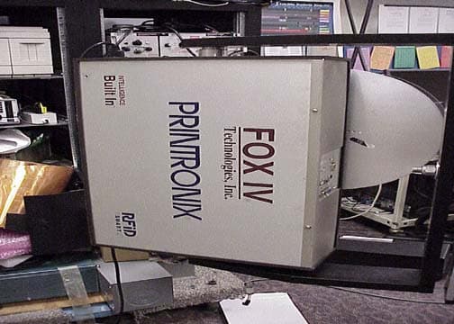
Click to zoom
Application Details
- Equipment Class
- DSS - Part 15 Spread Spectrum Transmitter
- Date of Grant
- Oct 24, 2005
- Application Purpose
- Original Equipment
- Date of Application
- Oct 24, 2005
- Equipment Note
- Print and Apply Machine
- Frequency Range
- 902.00000000 - 928.00000000
- Company
- Printronix Inc
- Country
- United States
Documents & Files
Document Text
Text extracted from the exhibit documents filed with the FCC. Open a document above to read the original.
Users Manual
SLPA7000 e Smart Label Printer Applicator Operator’s Reference Training Manual Operator’s Reference Training Manual SLPA7000 e Smart Label Printer Applicator IMPORTANT WARRANTY INFORMATION PRINTER WARRANTY Printronix ® warrants to purchaser that under normal use and service, this printer (excluding the thermal printhead) purchased hereunder shall be free from defects in material and workmanship for a period of ninety (90) days from the date of shipment from Printronix. Consumable items such as media and ribbons are not covered under this warranty. This warranty does not cover equipment or parts that have been misused, altered, or used for purposes other than those for which they were manufactured. This warranty also does not cover loss, shipping damage, damage resulting from accident or damages resulting from unauthorized service. THERMAL PRINTHEAD Printronix warrants the printhead for a period of one hundred eighty (180) days, or 1,000,000 linear inches for direct thermal use, or 2,000,000 linear inches for thermal transfer use, whichever comes first. The warranty does not cover printheads that have been misused, damaged due to improper cleaning, or damaged due to use of improper ribbons or media. SUPPLIES For the nearest Printronix full-service distributor that carries Printronix genuine supplies, please call (800) 733-1900 or fax (714) 368-2354. Supplies design, specification, and selection are integral to the development of any computer imaging system. Printronix’s extensive manufacturing and research capabilities, along with years of experience in the design of printers and their applications, assures that you will receive the exact materials that you require to maximize the performance of your Printronix printer. For more information, call the Printronix Customer Solutions Center at (714) 368-2686 or access the Printronix website at http://www.printronix.com. ON-SITE MAINTENANCE SERVICE Printronix offers on-site support services in the United States. Please contact the Printronix Maintenance Contracts Group at (714) 368-2798 for detailed service agreement information. COPYRIGHT 2005 PRINTRONIX, INC. 1 Setup Procedures ................................................ 7 Removing Label Backing...................................................................... 7 Threading The Label Roll ..................................................................... 8 Loading Ribbon .................................................................................. 16 Positioning The Air Jets...................................................................... 19 Calibrating The Printer ....................................................................... 20 Running Auto Calibrate ................................................................. 21 2 Control Panel ..................................................... 23 LCD .................................................................................................... 24 Keypad ............................................................................................... 24 Key and Indicator Descriptions........................................................... 26 Pneumatic Control Valves And Gauges ............................................. 28 Applicator Delay Menu ....................................................................... 29 QUICK SETUP Menu ......................................................................... 30 QUICK SETUP Menu Items .......................................................... 31 Saving The Configuration ................................................................... 37 Selecting The Power-Up Configuration .............................................. 37 Loading A Saved Configuration.......................................................... 37 3 Printing And Applying Labels ............................. 39 Printing And Applying Labels ............................................................. 39 Label Application (Positioning) Adjustments ................................. 39 Adjusting The Cylinder Extend Time ............................................. 41 The Print And Apply Process ........................................................ 42 4 Preventive Maintenance And Cleaning .............. 43 Cleaning ............................................................................................. 43 General Cleaning .......................................................................... 43 Cleaning The Printhead, Platen Roller And Media Sensors.......... 45 Cleaning Procedure ...................................................................... 45 Cleaning The Applicator Pad ........................................................ 46 Cleaning/Replacing The Vacuum Generator................................. 47 Cleaning Schedule ........................................................................ 48 Table of Contents Table of Contents System Adjustments........................................................................... 49 Printhead Pressure Adjustment .................................................... 49 Printhead Pressure Block Adjustments ......................................... 50 Positioning The Media Sensors .................................................... 50 Sensing Different Media Types ..................................................... 52 Calibrating The Media Sensors ..................................................... 57 5 Illustrated Parts Breakdown ............................... 61 Organization Of This Chapter............................................................. 61 Illustrated Parts Breakdown ............................................................... 61 7 1Setup Procedures Removing Label Backing If the media rewind spool needs to be unloaded during operation, proceed as follows: 1. Press the Pause key to take the SLPA offline. Disable the product sensor if necessary. 2. Tear the label backing near the media rewind hub, then reach around…
Text truncated - open the document above for the full version.
Users Manual
SLPA7000 r Smart Label Printer Applicator User’s Manual User’s Manual SLPA7000 r Smart Label Printer Applicator IMPORTANT WARRANTY INFORMATION PRINTER WARRANTY Printronix® warrants to the purchaser that under normal use and service, this printer (excluding the thermal printhead) purchased hereunder shall be free from defects in material and workmanship for a period of one year from the date of shipment from Printronix. (In the United States and Canada, this period provides for onsite support service in the first 90 days of ownership, with return-to-factory service provided from the 91st day of ownership until the end of one year, costs of shipping to be borne by the purchaser.) Consumable items such as media and ribbons are not covered under this warranty. This warranty does not cover equipment or parts that have been misused, altered, or used for purposes other than those for which they were manufactured. This warranty also does not cover loss, shipping damage, damage resulting from accident or damages resulting from unauthorized service. THERMAL PRINTHEAD Printronix warrants the printhead for a period of one hundred eighty (180) days, or 1,000,000 linear inches for direct thermal use, or 2,000,000 linear inches for thermal transfer use, whichever comes first. The warranty does not cover printheads that have been misused, damaged due to improper cleaning, or damaged due to use of improper ribbons or media. SUPPLIES For the nearest Printronix full-service distributor that carries Printronix genuine supplies, please call 1-800-733-1900 or fax (714)-368-2354. Supplies design, specification, and selection are integral to the development of any computer imaging system. Printronix's extensive manufacturing and research capabilities, along with years of experience in the design of printers and their applications, assures that you will receive the exact materials that you require to maximize the performance of your Printronix printer. For more information, call the Printronix Customer Solutions Center at (714) 368-2686 or access the Printronix website at http://www.printronix.com. ON-SITE MAINTENANCE SERVICE Printronix offers on-site support services in the United States and Canada. Please contact the Printronix Maintenance Contracts Group at 800-854-6463 - option 1 for detailed service agreement information. Model ____________ Setup Values Software Version___________________________ Touch-Blo Control___________________________ Print Mode___________________________ Apply Mode___________________________ Print Darkness___________________________ Machine Type___________________________ Pinch Roller___________________________ Random Stroke Delay___________________________ Cycle Time Delay___________________________ Cylinder Extend Time ___________________________ Vacuum Delay Time___________________________ CPU Dip Switch Settings __________________________ Printer Serial Number ___________________________ Communication Notices This equipment has been tested and found to comply with the limits for a Class B digital device, pursuant to Part 15 of the FCC Rules. These limits are designed to provide reasonable protection against harmful interference in a residential installation. This equipment generates, uses, and can radiate radio frequency energy and, if not installed and used in accordance with the instructions, may cause harmful interference to radio communications. However, there is no guarantee that interference will not occur in a particular installation. If this equipment does cause harmful interference to radio or television reception, which can be determined by turning the equipment off and on, the user is encouraged to try to correct the interference by one or more of the following measures: •Reorient or relocate the receiving antenna. •Increase the separation between the equipment and receiver. •Connect the equipment into an outlet on a circuit different from that to which the receiver is connected. •Consult the dealer or an experienced radio/TV technician for help. Unauthorized changes or modifications could void the user’s authority to operate the equipment. This device complies with part 15 of the FCC Rules. Operation is subject to the following two conditions: (1) this device may not cause harmful interference, and (2) this device must accept any interference received, including interference that may cause undesired operation. Any change or modification to this product voids the user’s authority to operate it per FCC Part 15 Subpart A Section 15.21 regulations. This product contains an intentional radiator with the following parameters: Operating Frequency: 902 to 928 MHz Typical RF Power: 25 to 100 milliwatts (SL5x04 MP) or 25 to 205 milliwatts (SL5x04 C1) Maximum RF Power: 1 Watt under abnormal conditions Canada This Class B digital apparatus complies with Canadian ICES-003 and RSS 210. Cet appareil numérique de la classe B est conforme à la norme NMB-003 du Canada. Operation is subject to the following two conditions: (1) this device may not cause interference, and (2) this device must accept any interference, including interference that may cause undesired operation of the device. This device has been designed to operate with the antennas listed below, and having a maximum gain of –18 dBi. Antennas not included in this list or having a gain greater than –18 dBi dB are strictly prohibited for use with this device. The required antenna impedance is 50 ohms. Tested To Comply With FCC Standards Printronix SL5000 r and T5000 r FOR HOME OR OFFICE USE To reduce potential radio interference to other users, the antenna type and its gain should be so chosen that the equivalent isotropically radiated power (e.i.r.p.) is not more than that permitted for successful communication. CE Notice (European Union) Marking by the CE symbol indicates compliance of this Printronix system to the EMC Directive and the Low Voltage Directive of the European Union. Such marking is indicative that this Printro…
Text truncated - open the document above for the full version.
Users Manual
76 Chapter3Moving Within The Configuration Menu 4. When the desired number displays, press the ↵ key to select it. The following message displays briefly: When processing is completed, the display shows: NOTE:If the configuration number has been previously saved and Protect Configs. = Enabled under CONFIG CONTROL, the following error message displays: If the above occurs, see “Modifying A Saved Configuration” on page 78, step 4. 5. Print your configuration and store it in a safe place for future reference. Refer to “Printing A Configuration” on page 79. Auto Save Configuration If you make any changes to the factory default configuration menu items, you will be prompted to save the changes to “Config #” when you place the printer online. “#” equals the next available unassigned configuration number. When prompted, press one of the following keys: •Enter. Saves to Config 1 or the next available Config, and becomes the power-up config. NOTE:If all eight Configs are assigned, you will be prompted to select which Config to overwrite. •Pause. Changes will be implemented but saved only temporarily until deliberately saved as a new configuration or until you power off the printer. All changes will be lost when you power off the printer. Saving Configuration Save Config. X* CONFIG. EXISTS Delete First Specifying A Power-Up Configuration 77 Specifying A Power-Up Configuration You can specify any one of the nine configurations (1-8 or Factory) as the power-up configuration: 1. Press the key until the following message displays: 2. Press the ↓ key until the following message displays: 3. Press the + or – key to cycle through the options (1-8 and Factory). When the desired number displays, press the ↵ key to select it. The following message displays: NOTE:If the configuration number has not been saved previously, the following error message displays: If this error message displays, see “Saving A Configuration” on page 75. Once you have saved a configuration, repeat the steps in this procedure. . . . MENU MODE CONFIG. CONTROL Power-Up Config. 1* Power-Up Config. X* CONFIG. DOES NOT EXIST/Save First 78 Chapter3Moving Within The Configuration Menu Modifying A Saved Configuration You can change a saved configuration by rewriting over it. For example, you can modify Config. 1, shown below. Suppose you want to keep all the settings but you want to select the parallel Centronics interface instead of the IEEE 1284 interface. 1. Load the configuration to be changed (for example, Config. 1). a. Press the key until the following message displays: b. Press the ↓ key until the following message displays: c. Press the + or – key to cycle through the options: Factory 1-8. d. When the desired number displays, press the ↵ key to select it. The following message displays: Then, the following message displays when it is loaded: 2. Move through the menu and change all the desired values. (In this example, press the key until PARALLEL PORT displays. Press the ↓ key until Port Type/IEEE 1284 displays. Press the - key until Centronics displays.) 3. Press the ↵ key to select each new value. An asterisk (*) displays. 4. Before saving the modified configuration, you must delete the original configuration if the Protect Configs. option is enabled. a. Press the ↑ or ↓ key until the following message displays: b. Press the + or – key to cycle through the options (1-8). When the desired number displays, press the ↵ key to select it. The following message displays: . . . MENU MODE CONFIG. CONTROL Load Config. Factory Loading Saved Configuration Load Config. X* . . . Delete Config. 1* Deleting Configuration Printing A Configuration 79 Then, the following displays when it is deleted: 5. Save the new configuration as described in the “Saving A Configuration” on page 75. Make sure you select the same number (e.g., Config. 1) when saving the modified configuration. The new configuration writes over the existing one. 6. Print a copy of this newest configuration and store it in a safe place. Refer to “Printing A Configuration” on page 79. Printing A Configuration We recommend that you print and store your configurations for future reference. The printout provides a list of the parameters that were set when you configured the printer. To print a configuration: 1. Press the key until the following message displays: 2. Press the ↓ key until the following message displays: 3. Press the + or – key to cycle through the following printout options: Current* Factory Power-Up All 1-8 customized configurations 4. When the desired option displays, press the ↵ key. The printer prints the specified configuration. NOTE:If the configuration you want to print has not been saved, the following message displays momentarily: This message indicates that no configuration menu has been saved under the configuration value you have selected and therefore cannot be printed. You must either select another configuration to print or load and then save a configuration to that configuration value first. Delete Config. X* . . . MENU MODE CONFIG. CONTROL Print Config. Current* CONFIG. DOES NOT EXIST/Save First 80 Chapter3Moving Within The Configuration Menu Figure 29. Sample Configuration Printout Printing A Configuration 81 Sample Configuration Printout (cont.) 82 Chapter3Main Menus Main Menus Load Config. Save Config. Print Config. Delete Config. Power-Up Config. Protect Configs. Name Config 1 Name Config 2 Name Config 3 Name Config 4 Name Config 5 Name Config 6 Name Config 7 Name Config 8 Reset Cfg Names CONFIG. CONTROL (page 105) NOTES: Italicized items appear only if Admin User is set to Enable (in the PRINTER CONTROL menu). 1 Gap/Mark Sensor and Paper Out Sensor work in conjunction, as shown in the T5000r User’s Manual. If you change the Gap/Mark Sensor or Paper Out Sensor, you must recalibrate the media. 2 Display item only. RFID CONTROL (page 97) RFID Reader Tag Type Error Handling Label Retry Max Retry Error Tag Write Cnt 2 Failed Tag Cnt 2 Tag Void Cnt 2 Tag R…
Text truncated - open the document above for the full version.
Cover Letter(s)
ISO 9000 Registered Worldwide 14600 Myford Road, P.O. Box 19559 Irvine, California 92623-9559 Telephone (714) 368-2300 Fax (714) 368-2941 http://www.printronix.com September 21, 2005 Federal Communications Commission 7435 Oakland Mills Road Columbia, MD 21046 Gentlemen: This letter is to comply with Section 0.457 and 0.459 pertaining to confidential material. Printronix would like the following documents regarding this submission for FCC ID: E5A-ADMP2PA and IC: 5448A- ADMP2PA to be kept confidential. 1. List file name or type of information. All Schematics. The above material contains trade secrets or technical data, which would customarily be guarded from competitors. We do not want these documents to be accessible to the general public. Sincerely, Zaven Mangassarian Sr. Product Safety / EMC Engineer
Cover Letter(s)
Response to E05-000320-1 1. A confidentiality letter has been uploaded. 2. An operational description has been uploaded. 3. A user’s manual has been uploaded. 4. a. The test report has been revised to show the AC power was varied from 85% to 115%. b. This modification was done on the portion that would only reduce the radiated emission, ie removing paint on the part that shied the antenna, relocate antenna. Hence, conducted emissions is not needed since conducted emissions is a direct measurement. E05-000320-1 IC 1. An operational description has been uploaded. 2. A user’s manual has been uploaded.
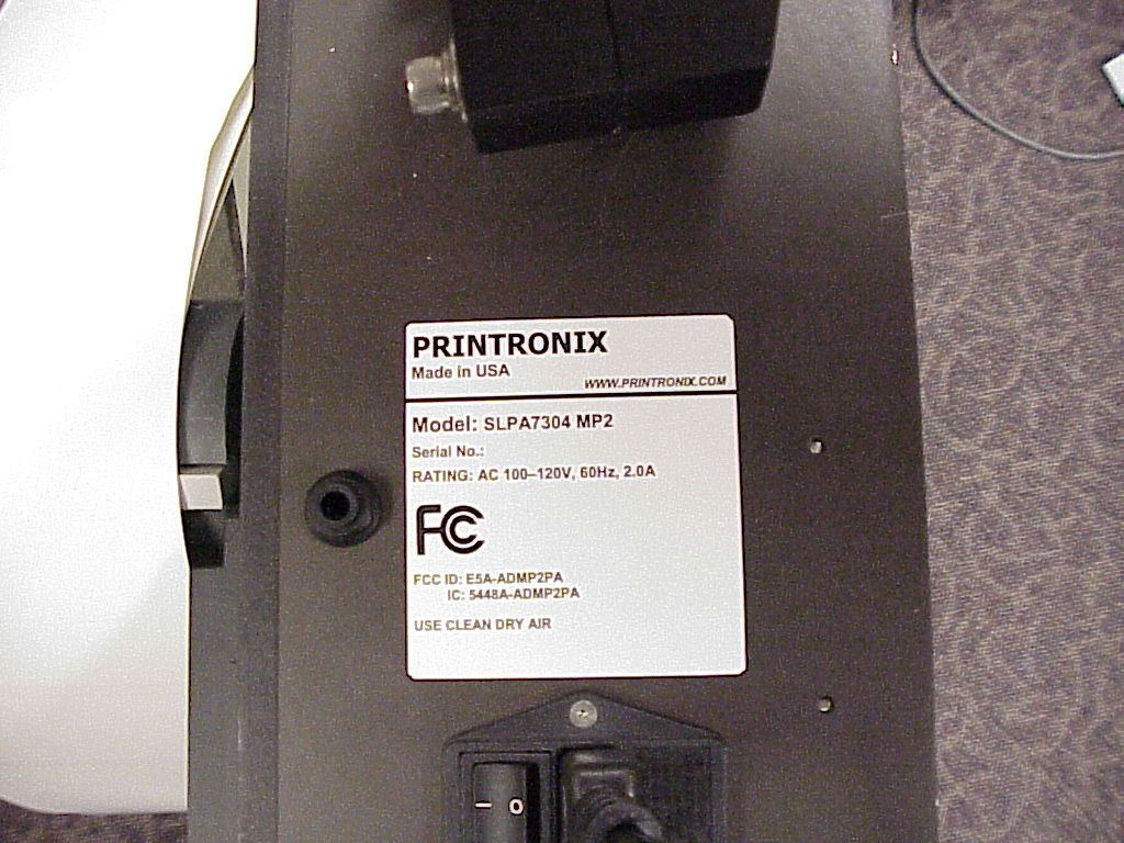
ID Label/Location Info
PRINTRONIX Made in USA WWW.PRINTRONIX.COM Model: SLPA7204 MP2 Serial No.: RATING: AC 100–120V, 60Hz, 2.0A FCC ID: E5A-ADMP2PA IC: 5448A-ADMP2PA USE CLEAN DRY AIR
Internal Photos
Front Inside Top Inside Top 1 Inside Top 2 Inside Top 3 Inside Top 3 left Inside Top 4 Inside Top 5 Inside Top 6 Inside Top 7 Board 1 Top Board 1 Top Half Board 1 Bottom Board 2 Back and Front Board 2 Back RFID Interface Board Front RFID Interface Board Back RFID Interface Board Top RFID Interface Board Left Side RFID Interface Board Right Side RFID Interface Small Board Front RFID Interface Small Board Back RFID Reader Module Cover RFID Reader Module Top RFID Reader Module Back RFID Reader Module Inside 1 RFID Reader Module Inside 2 RFID Reader Module Inside 3 RFID Reader Module Inside 4 RFID Reader Module Inside 5 RFID Reader Module Inside 6
Operational Description
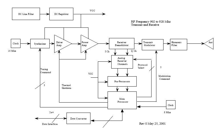
RFID OPERATIONAL DESCRIPTION The RFID Tags: An RFID Tag is made up of a microchip anchored to a strap, which is attached to an antenna and encased in a protective inlay. The actual chip is no bigger than a grain of sand. The antenna however is big enough to allow the tag to be read at a distance of 10 feet (3 meters). Printronix Smart Label RFID printers use Passive Tags. Passive Tags have no battery; instead, they draw power from the reader’s antenna. Electromagnetic waves transmitted from the antenna, induces a current in the tag’s antenna; The Tag uses the energy to power the chip and talk back to the reader. When passive Tags are not in the presence of a reader they are not capable of emitting any radio signal by themselves. RFID Printer: Passive Tags have no data in them. They require an encoding step to prepare them for use. Encoding can be done by a reader built into the RFID printer, or, any reader that is setup for the task. When writing data to a tag, a reader has to address a tag individually. The tag must be within the proximity of the reader for the time it takes to program it. The tag must be able to draw sufficient power from the reader to enable the programming circuitry in the tag. . In RFID printers, tags are encapsulated in a roll of smart labels, at a close proximity of the antenna to utilize the advantage of near field electromagnetism for inductive coupling to the tag. RFID Readers: RFID readers use backscatter reflection, to energize tags and read their response. A reader uses its antenna to send digital information encoded in amplitude modulation (AM) waveform. A receiver circuit on the tag is able to detect the modulation field, decode the information, and use its own antenna to send an AM signal response. To avoid collision between tags (reading multiple tags at a time), the printer uses software algorithm to allow tags to be sorted and individually selected.
RF Exposure Info
5473A Clouds Rest Road : Mariposa, CA 95338 : Phone 209-966-5420 : Fax 209-742-6133 FCC 1.1310(b), Maximum Permissible Exposure Calculations RSS133 Sun clause 8 Exposure of Humans to RF Field Date of Report: 07/19/2005 Calculations prepared for: Printronix PO Box 19559 Irvine CA 92623-9559 Calculations prepared by: Eddie Wong 110 N. Olinda Place Brea, CA 9283 Model Number: SLPA7204r FCC Identification: NA Fundamental Operating Frequency: 902-928MHz Maximum Rated Output Power: 0.08710 Measured Output Power: 0.08710 MPE Limit in accordance with 1.1310(b): Limits for general population/uncontrolled exposure MPE Limit for 902-928 MHz = 0.6 mW/cm 2 (6 W/m 2 ) 1 Power Output (Watts) Power Density Limit (mW/cm 2 ) Minimum Distance (Meters) 0.08710 0.6 0.034m P t = Power Delivered to the Antenna G = Antenna Gain d = Distance in meters Zo = Impedance of Free Space The typical antennas to be used with the EUT are structure mount antennas which under normal operation has an enclosure that keep a distance of at least 0.1 m from the user. As can be seen from the MPE result, this device passes the limit specified in 1.1310 at a distance of 0.034 meter. Calculation: 0 2 t 2 x Zd G x P x 30 )(W/m Density Power= = 0.034meter. 377 x 6 1 x 08710.0 x 30 d=
Test Report
Page 1 of 68 Report No: FC05-033A ADDENUDM TO PRINTRONIX TEST REPORT FC05-033 FOR THE PRINT AND APPLY MACHINE, SLPA7304R MP2 FCC PART 15 SUBPART C SECTIONS 15.207 & 15.247 AND RSS-210 COMPLIANCE DATE OF ISSUE: SEPTEMBER 9, 2005 PREPARED FOR: Printronix P.O. Box 19559 Irvine, CA 92623-9559 PREPARED BY: Mary Ellen Clayton CKC Laboratories, Inc. 5046 Sierra Pines Drive Mariposa, CA 95338 P.O. No.: W.O. No.: 3503847 83794 Date of test: May 31 – July 19, 2005 Report No.: FC05-033A This report contains a total of 68 pages and may be reproduced in full only. Partial reproduction may only be done with the written consent of CKC Laboratories, Inc. The results in this report apply only to the items tested, as identified herein. Page 2 of 68 Report No: FC05-033A TABLE OF CONTENTS Administrative Information .............................................................................................4 FCC to Canada Standard Correlation Matrix...................................................................5 Conditions for Compliance ..............................................................................................5 Approvals .........................................................................................................................5 Equipment Under Test (EUT) Description ......................................................................6 FCC 15.31(e) Voltage Variation......................................................................................6 FCC 15.31(m) Number Of Channels ...............................................................................6 FCC 15.33(a) Frequency Ranges Tested .........................................................................6 FCC 15.35 Analyzer Bandwidth Settings ........................................................................6 FCC 15.203 Antenna Requirements ................................................................................6 Eut Operating Frequency .................................................................................................6 Equipment Under Test .....................................................................................................7 Peripheral Devices ...........................................................................................................7 Report of Measurements ..................................................................................................8 Table 1: FCC 15.207 Six Highest Conducted Emission Levels ..........................8 FCC 15.247 (A)(1)(I) 20dB .................................................................................9 Fcc 15.247 (a)(1)(i) Average Time Of Occupancy..............................................12 FCC 15.247(a)(1)(iii) Number Of Hopping Frequencies ....................................14 FCC 15.247 (b)(3) RF Power Output ..................................................................15 Bandedge Plot ......................................................................................................16 FCC 15.247 Carrier Frequency Separation..........................................................18 Table 2: FCC 15.247(d) Six Highest Radiated Emission Levels.........................19 FCC 15.247(d) Antenna Conducted Emission Levels .........................................20 RSS-210 99% Bandwidth ....................................................................................21 Temperature And Humidity During Testing....................................................................24 EUT Setup........................................................................................................................24 Correction Factors............................................................................................................24 Table A: Sample Calculations .............................................................................24 Test Instrumentation and Analyzer Settings ....................................................................25 Spectrum Analyzer Detector Functions ...............................................................25 Peak..........................................................................................................25 Quasi-Peak ...............................................................................................25 Average ....................................................................................................25 EUT Testing.....................................................................................................................26 Mains Conducted Emissions................................................................................26 Antenna Conducted Emissions ............................................................................26 Radiated Emissions ..............................................................................................26 Appendix A: Test Setup Photographs..............................................................................28 Photograph Showing Mains Conducted Emissions .............................................29 Photograph Showing Mains Conducted Emissions .............................................30 Photograph Showing Radiated Emissions ...........................................................31 Photograph Showing Radiated Emissions ...........................................................32 Page 3 of 68 Report No: FC05-033A Photograph Showing Radiated Emissions ...........................................................33 Photograph Showing Direct Connect Test Setup.................................................34 Photograph Showing Direct Connect Test Setup.................................................35 Appendix B: Test Equipment List ...................................................................................36 Appendix C: Measurement Data Sheets ..........................................................................37 Page 4 of 68 R…
Text truncated - open the document above for the full version.
Test Report
Page 1 of 68 Report No: FC05-033A ADDENUDM TO PRINTRONIX TEST REPORT FC05-033 FOR THE PRINT AND APPLY MACHINE, SLPA7304R MP2 FCC PART 15 SUBPART C SECTIONS 15.207 & 15.247 AND RSS-210 COMPLIANCE DATE OF ISSUE: SEPTEMBER 9, 2005 PREPARED FOR: Printronix P.O. Box 19559 Irvine, CA 92623-9559 PREPARED BY: Mary Ellen Clayton CKC Laboratories, Inc. 5046 Sierra Pines Drive Mariposa, CA 95338 P.O. No.: W.O. No.: 3503847 83794 Date of test: May 31 – July 19, 2005 Report No.: FC05-033A This report contains a total of 68 pages and may be reproduced in full only. Partial reproduction may only be done wi…
Text truncated - open the document above for the full version.
Contact Information
Applicant
Andrew Edwards(Director, Product Development)
Technical Contact
CKC Laboratories, Inc.Mary Ellen Clayton
[email protected]800-500-4362
5046 Sierra Pines Drive · Mariposa, California · United States
Test Firm
CKC Laboratories, Inc.Steve Behm
Technical Specifications
| # | Rule Parts | Frequency Range | Power Output |
|---|---|---|---|
| 1 | 15C | 902 MHz - 928 MHz | 87.00 mW |
Other Applications from Printronix Inc
E5A-M4LWK
Mar 08, 2015Bar Code Printer
Equipment Class
DTS - Digital Transmission System
E5A-M4LWG
May 21, 2014Bar Code Printer
Equipment Class
DTS - Digital Transmission System
E5A-ADMP2
Oct 05, 2005RFID Printer
Equipment Class
DSS - Part 15 Spread Spectrum Transmitter
E5A-AN2RFID
Aug 03, 2004Printer
Equipment Class
DSS - Part 15 Spread Spectrum Transmitter
E5A-ADRFID
Nov 13, 2003RFID Enabled Thermal Printer
Equipment Class
DSS - Part 15 Spread Spectrum Transmitter