ECPDB2000Graphic Digitizer
eInstruction GTCO Holdings LLC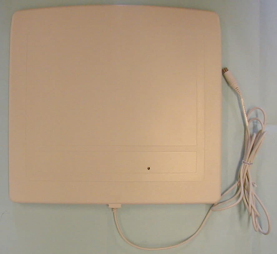
Click to zoom
Application Details
- Equipment Class
- JBP - Part 15 Class B Computing Device Peripheral
- Date of Grant
- Jul 12, 2000
- Application Purpose
- Original Equipment
- Date of Application
- Apr 17, 2000
- Equipment Note
- Graphic Digitizer
- Country
- United States
Documents & Files
Document Text
Text extracted from the exhibit documents filed with the FCC. Open a document above to read the original.
External Photos
Page 1 of 1 file://D:\Working\pictures\P3080009.JPG4/20/00
External Photos
Page 1 of 1 file://D:\Working\pictures\P3080010.JPG4/20/00
External Photos
Page 1 of 1 file://D:\Working\pictures\P3080012.JPG4/19/00
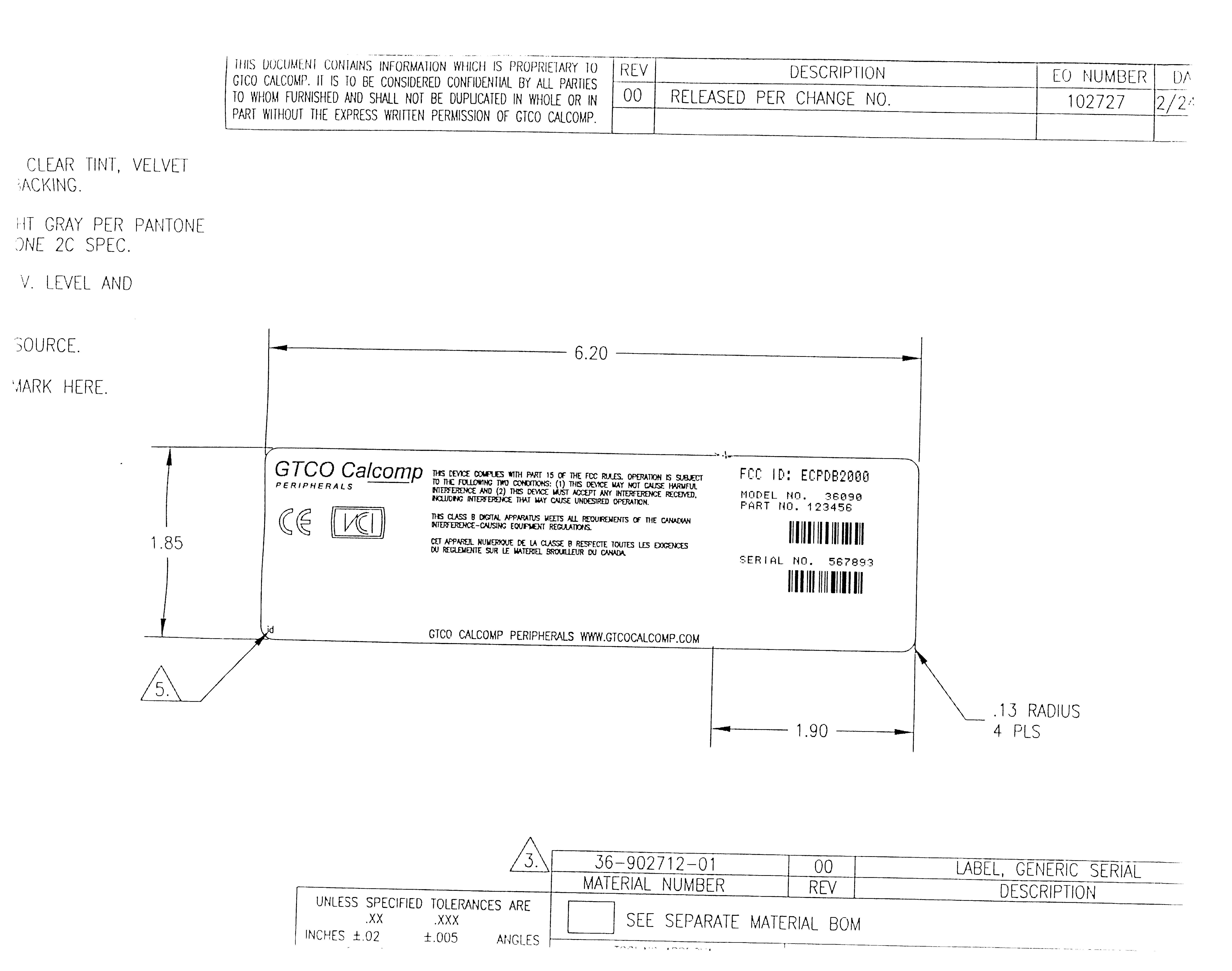
ID Label/Location Info
Page 1 of 2 file://D:\Working\P3080010.JPG4/19/00 Page 2 of 2 file://D:\Working\P3080010.JPG4/19/00
ID Label/Location Info
Page 1 of 1 file://D:\Working\pictures\P3080010.JPG4/20/00
Internal Photos
Page 1 of 1 file://D:\Working\pictures\P3080007.JPG4/20/00
Internal Photos
Page 1 of 1 file://D:\Working\pictures\P3080002.JPG4/20/00
Internal Photos
Page 1 of 1 file://D:\Working\pictures\P3080003.JPG4/20/00
Test Report
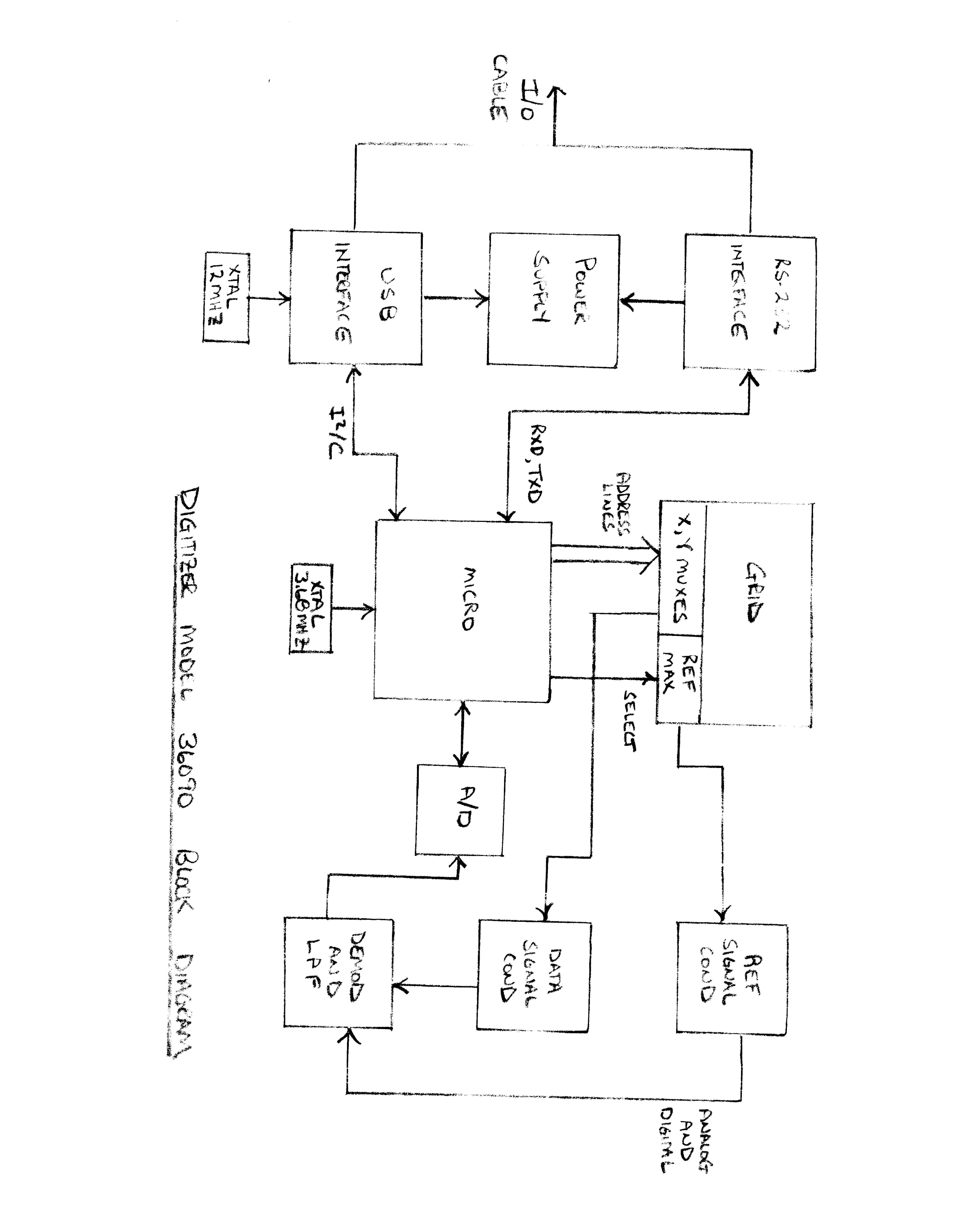
TEST REPORT TO FCC PART 15 SUBPART B AND EN55022 FOR: GTCO CalComp Digitizer Model 36090 FCC ID: ECPDB2000 PREPARED FOR: GTCO CalComp 14555 North 82nd Street Scottsdale, AZ 85260 PREPARED BY: Kenneth B. Jacobson Product Support Engineer GTCO Calcomp 14555 North 82nd Street Scottsdale, AZ 85260 DATE OF REPORT: 04/13/00 - 1 - TABLE OF CONTENTS CONTENTPAGE I.Overview of Test Report........................................................................................2 II.Statement of Compliance.......................................................................................3 III.Description of the Test Sample..............................................................................4 IV.List of Subassemblies of Test Sample (If Applicable)............................................5 V.Test Equipment and Calibration............................................................................6 VI.Cable Loss and Antenna Factors...........................................................................7-13 VII.Description of Equipment and Cables Used for Testing........................................14 VIII.Radiated Test Procedure.......................................................................................15 IX.Radiated Test Data/Photographs..........................................................................16-18 X.Conducted Test Procedure....................................................................................19 XI.Conducted Test Data/Photographs.......................................................................20-28 XII.Summary of Results...............................................................................................29 - 2 - I.OVERVIEW OF TEST REPORT The procedures used for the conducted and radiated tests were derived from the American National Standard ANSI C63.4-1991 as stated in FCC CFR 47, Part 15, Paragraph 15.31. The test site attenuation and layout was done in accordance with ANSI C63.4-1991 and is on file with the FCC as required in FCC CFR 47, Part 2, Paragraph 2.948. PRODUCT TESTED:GTCO CalComp Digitizer Model 36090 TRADE NAME:ArtistPro or CADPro APPLICANT:GTCO CalComp 14555 North 82nd Street Scottsdale, AZ 85260 MANUFACTURER:Same as Applicant TEST FACILITY LOCATION:Same as Applicant TEST DATE:03/09/00 The measurement data contained in this report reflects an accurate representation of the emission characteristics of the produce mentioned above. REPORT PREPARED AND APPROVED BY: Kenneth B. Jacobson Kenneth B. Jacobson Product Engineer GTCO CalComp - 3 - II.STATEMENT OF COMPLIANCE Under the test configuration as described in this test report, the product tested has shown that it complies to the requirements of: FCC RULES, PART 15, SUBPART B, CLASS B LIMITS The product tested has shown that it also complies to the requirements of: EC STANDARD EN55022/CISPR 22, CLASS B LIMITS We, GTCO CalComp, assume full responsibility to manufacture the product as shown in the enclosed photographs to uphold compliance to the FCC rules. SIGNED:Randy Crutchfield Randy Crutchfield TITLE: Manager of Engineering - 4 - III. DESCRIPTION OF TEST SAMPLE The GTCO CalComp Digitizer Model 36090, is a microprocessor-based device that can convert graphic information into accurate digital information for entry into the host computer. The digitizer can be used for drawing, drafting, mapping, desktop publishing, animation, menuing and presentation graphics. The basic operation of the digitizer is as follows: An AC current flowing in the transducer electromagnetically induces voltages into precisely positioned conductors beneath the tablet’s surface. The tablet electronics finds the tablet grid conductors with the largest signals and converts the grid signals into digital position data. The tablet sends the information out the communication port to the host. The data generated indicates the distance vertically and horizontally from the origin on the digitizer’s surface. The digitizer can support either RS-232 or USB interfaces. The digitizer comes with a ‘universal cable’ which has a 8 pin mini-din connector on the end. Depending which interface the end user wants to use, they will either plug in a RS-232 adapter or a USB adapter which is supplied with the digitizer into the 8 pin mini-din. The digitizers firmware will determine which interface it will support. Photo’s of the adapters is included with the photos of the digitizer. The digitizer receives it’s power from the host computer and the transducer (mouse) is battery operated and is approve by the FCC under Part 15, Subpart C. - 5 - IV.SUBASSEMBLIES OF TEST SAMPLE The GTCO CalComp Digitizer Model 36090 consists of a single PCB board and the only subassemblies would be a mouse or the I/O adapters. See attached photographs. - 6 - V.TEST EQUIPMENT AND CALIBRATION The following is a list of equipment and calibration dates that are used at GTCO CalComp’s test site. TEST EQUIPMENTMODEL CALIBRATION DATEFREQUENCY Com-Power Log Periodic Antenna CPAL-10006/08/991 Year Com-Power Biconical AntennaAB-10005/28/991 Year Com-Power Loop AntennaAL-13006/26/991 Year EMCO LISN3825/209/25/991.5 Year EMCO LISN3825/209/25/991.5 Year HP Spectrum Analyzer with Quasi-Peak Adapter 8568B 85650A 11/10/991 Year HP Signal GeneratorHP8656B09/15/991 Year EMCO Turntable1060N/AN/A HP PlotterHP7470N/AN/A CableRG-59/U05/13/991 Year - 7 - VI. CABLE LOSS AND ANTENNA FACTORS - 8 - - 9 - - 10 - - 11 - - 12 - - 13 - RG 59/U 3 METER CABLE LOSS MHzLOSS (db)MHzLOSS (db) 2801.30 30.472901.37 35.313001.61 40.643101.28 45.773201.53 50.703301.71 55.693401.99 60.763501.84 65.673602.11 70.483702.06 75.363801.82 80.233902.29 85.164002.02 90.124102.18 95.194202.12 100.244302.31 105.314402.43 110.484502.57 115.714602.62 120.454703.03 125.464803.04 130.504903.18 135.615003.21 140.615252.94 145.465502.54 150.585752.85 155.876003.18 160.956253.15 165.486503.54 170.486753.71 175.757003.93 1801.237254.08 1851.077503.70 190.437753.65 195.388003.52 200.588254.41 210.…
Text truncated - open the document above for the full version.
Contact Information
Applicant
Dana Doubrava
Technical Contact
GTCO CalCompKen B Jacobson
[email protected]480-443-2230
14555 N. 82nd Street · Scottsdale, Arizona · United States
Non-Technical Contact
GTCO CalCompKen B Jacobson
[email protected]480-443-2230
Test Firm
GTCO CalcompKenneth Jacobson
Technical Specifications
| # | Rule Parts | Frequency Range | Power Output |
|---|---|---|---|
| 1 | 15B | - | - |
Other Applications from eInstruction GTCO Holdings LLC
ECPMENUPAD
May 20, 2001MENUPAD
Equipment Class
DXT - Part 15 Low Power Transceiver, Rx Verified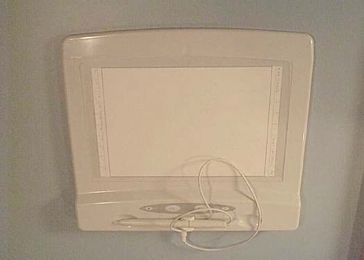
ECPDBIRF916
May 07, 2001Meeting Pad, 36080
Equipment Class
DXT - Part 15 Low Power Transceiver, Rx Verified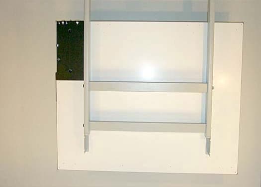
ECPRFDBI
May 07, 2001Drawingboard Interactive 4256
Equipment Class
DXT - Part 15 Low Power Transceiver, Rx Verified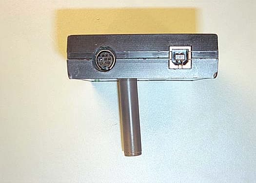
ECPJUNCTIONBOX
May 07, 2001Junction Box for Host Computer
Equipment Class
DXT - Part 15 Low Power Transceiver, Rx Verified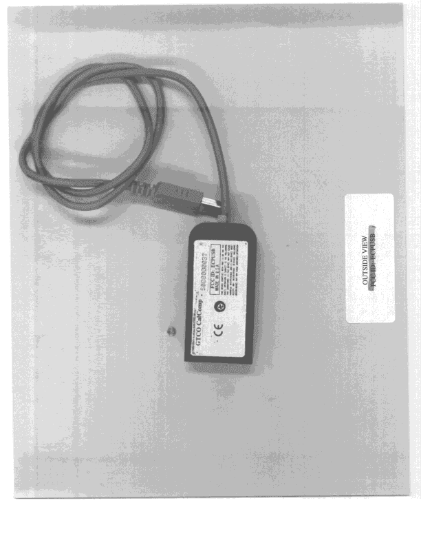
ECPUSB
Jul 05, 1999JBP - Part 15 Class B Computing Device Peripheral
Equipment Class
JBP - Part 15 Class B Computing Device Peripheral