EGTRCT200ADigital Remote Control System
Cattron North America Inc.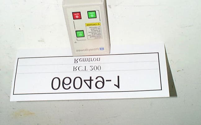
Click to zoom
Application Details
- Equipment Class
- DSC - Part 15 Security/Remote Control Transmitter
- Date of Grant
- Mar 05, 2000
- Application Purpose
- Original Equipment
- Date of Application
- Feb 21, 2000
- Equipment Note
- Digital Remote Control System
- Frequency Range
- 433.00000000 - 433.00000000
- Company
- Cattron North America Inc.
- Country
- United States
Documents & Files
Document Text
Text extracted from the exhibit documents filed with the FCC. Open a document above to read the original.
Users Manual
File: RCS200 Rev. A 2-08-00 REMTRON, INC. 1916 W. Mission Rd., Escondido, CA 92029-1114 PHONE 760-737-7800 FAX 760-737-7810 REMOTE CONTROL AND TELEMETRY SYSTEMS RCS200 Radio Remote Control System User's Manual This manual covers the following Remtron models: RCT200 Transmitter RCR200 Receiver 1.1 SECTION 1 GENERAL WARNING SAFETY PROCEDURES Safety is an extremely high priority in every remote control system designed and manufactured by Remtron. Although every effort has been made to provide a product with the most complete array of safety features, each application has its own unique requirements. Remtron and its agents cannot be held responsible, for any breach of safety, carelessness, improper or unauthorized use of the remote control system or the equipment it is intended to control. Each customer is responsible for safe and proper use of the equipment. Each customer is also responsible that the employees involved with this equipment know, understand and use proper installation, operating and maintenance procedures and that they are aware of and adhere to all established safety rules and regulations as they apply. 1.1 INTRODUCTION The RCS200 is a digital remote control system for applications that require a high level of reliability and integrity. It is designed for short range, license free operation of industrial and commercial equipment. Intended primarily for OEM applications, the number of functions and the receiver interface is determined by the user's application. 1.2 SYSTEM DESCRIPTION The basic system consists of an RCT200 Transmitter and an RCR200 Receiver. The signal format consists of a Amplitude Shift Keyed (ASK) signal that carries a 24 bit address, 8 data bits and is verified through a 16 bit CRC check word. Data is transmitted using Manchester format at a 4800 baud rate. The address is permanently programmed into the transmitter at the factory and cannot modified. The receiver uses a learn mode to copy the address code from a transmitter and store it in memory. 1.3 TRANSMITTER DESCRIPTION The transmitter is housed in a plastic case with membrane switches for control inputs. Inputs are encoded by a microprocessor and transmitted using burst mode ASK. Figure 1-1 shows a block diagram of the transmitter. When a switch is activated, power is applied to the transmitter. The microprocessor encodes and sends a packet containing the address, data and CRC check word to the Transmitter IC. The packet is repeated every 60 m-sec as long as any switch is activated. When all switches are released, power is removed from the transmitter. The transmitter IC is an integrated frequency multiplying PLL with a power output stage. It uses a fixed ÷ 32 prescaler so the output frequency is set at 32 times the reference crystal. The transmitter antenna consists of a matched loop on the circuit board. 1.2 The Transmitter IC has a sleep mode which is used to conserve battery power. Each time a packet is sent, the transmitter is enabled 6 m-sec before modulation is applied to allow it to stabilize. After the data is sent, the transmitter again enters the sleep mode. The transmitter is therefore enabled approximately 20% of the time it is transmitting data. 1.4 RECEIVER DESCRIPTION The receiver consists of an ASK receiver and a microprocessor with up to four output relays. The receiver is powered from 12 or 24 VDC. Received data is passed directly to the microprocessor where the Manchester signal is decoded. The data packet is examined for an address match with the stored address, and correct CRC check. If both the address and the CRC are correct, the data is decoded and the output relay states are updated. The microprocessor contains a nonvolatile memory (EEPROM) that retains the address and particular operating parameters for the system. The output relays are factory programmed for the desired operation. The simplest configuration closes each relay as long as the corresponding switch on the transmitter is depressed. Complex and interactive relay logic is possible. Safety Features Each transmission goes through several checks to insure that the information being received is error free, including a 16 bit CRC test. Over 16 million address codes means that no two systems will ever be produced with the same code, thereby insuring that no transmitter will ever be able to unintentionally control another piece of equipment. Diagnostics A number of optional diagnostic LEDs can be provided to aid in troubleshooting the radio control system. 1.5 SPECIFICATIONS Table 2.1 Lists the specifications for the system. SECTION 1 GENERAL Microprocessor Transmitter IC. Power Switch Serial Data Internal Loop Antenna + 5 VDC Regulator +5V Figure 1-1 Transmitter Block Diagram 9 VDC Battery 1.5 Table 1.1 Specifications System Operating frequency band433 MHz Available Channels5 Channels Number of Commands8 maximum* ModulationDigital ASK with 24 bit address plus 16 bit CRC Ambient Operating Conditions- 20 O F to +160 O F Transmitter Power requirements9V battery. Alkaline recommended. AntennaInternal Switch TypesMembrane. Transmitter case dimensions4.5 X 2.7 X 1.25 Inches RECEIVER Power input12/24 VDC Receiver typeASK AntennaExternal* Logic BaseMicroprocessor controlled Response time60 milliseconds Output rating (relay)5 Amp @ 12 VDC Receiver cabinet4.125 X 2.75 X 1.0 Inches * Receiver antenna and configuration depends on system requirements. SECTION 1 GENERAL 5.1 SERVICE Repairs Products in need of repair may be returned to your dealer or sent directly to the factory at the address listed below. We recommend calling the factory for a Return Material Authorization (RMA) number prior to sending in the equipment. A note should be included describing the nature of the problem and the conditions under which the problem occurred. Also included with the returned product, should be the name, address and phone number where the product is to be returned and the name and phone number of a person familiar with the problem, who we may …
Text truncated - open the document above for the full version.
Operational Description
File: RCS200 Rev. A 2-08-00 REMTRON, INC. 1916 W. Mission Rd., Escondido, CA 92029-1114 PHONE 760-737-7800 FAX 760-737-7810 REMOTE CONTROL AND TELEMETRY SYSTEMS RCS200 Radio Remote Control System User's Manual This manual covers the following Remtron models: RCT200 Transmitter RCR200 Receiver 1.1 SECTION 1 GENERAL WARNING SAFETY PROCEDURES Safety is an extremely high priority in every remote control system designed and manufactured by Remtron. Although every effort has been made to provide a product with the most complete array of safety features, each application has its own unique requirements. Remtron and its agents cannot be held responsible, for any breach of safety, carelessness, improper or unauthorized use of the remote control system or the equipment it is intended to control. Each customer is responsible for safe and proper use of the equipment. Each customer is also responsible that the employees involved with this equipment know, understand and use proper installation, operating and maintenance procedures and that they are aware of and adhere to all established safety rules and regulations as they apply. 1.1 INTRODUCTION The RCS200 is a digital remote control system for applications that require a high level of reliability and integrity. It is designed for short range, license free operation of industrial and commercial equipment. Intended primarily for OEM applications, the number of functions and the receiver interface is determined by the user's application. 1.2 SYSTEM DESCRIPTION The basic system consists of an RCT200 Transmitter and an RCR200 Receiver. The signal format consists of a Amplitude Shift Keyed (ASK) signal that carries a 24 bit address, 8 data bits and is verified through a 16 bit CRC check word. Data is transmitted using Manchester format at a 4800 baud rate. The address is permanently programmed into the transmitter at the factory and cannot modified. The receiver uses a learn mode to copy the address code from a transmitter and store it in memory. 1.3 TRANSMITTER DESCRIPTION The transmitter is housed in a plastic case with membrane switches for control inputs. Inputs are encoded by a microprocessor and transmitted using burst mode ASK. Figure 1-1 shows a block diagram of the transmitter. When a switch is activated, power is applied to the transmitter. The microprocessor encodes and sends a packet containing the address, data and CRC check word to the Transmitter IC. The packet is repeated every 60 m-sec as long as any switch is activated. When all switches are released, power is removed from the transmitter. The transmitter IC is an integrated frequency multiplying PLL with a power output stage. It uses a fixed ÷ 32 prescaler so the output frequency is set at 32 times the reference crystal. The transmitter antenna consists of a matched loop on the circuit board. 1.2 The Transmitter IC has a sleep mode which is used to conserve battery power. Each time a packet is sent, the transmitter is enabled 6 m-sec before modulation is applied to allow it to stabilize. After the data is sent, the transmitter again enters the sleep mode. The transmitter is therefore enabled approximately 20% of the time it is transmitting data. 1.4 RECEIVER DESCRIPTION The receiver consists of an ASK receiver and a microprocessor with up to four output relays. The receiver is powered from 12 or 24 VDC. Received data is passed directly to the microprocessor where the Manchester signal is decoded. The data packet is examined for an address match with the stored address, and correct CRC check. If both the address and the CRC are correct, the data is decoded and the output relay states are updated. The microprocessor contains a nonvolatile memory (EEPROM) that retains the address and particular operating parameters for the system. The output relays are factory programmed for the desired operation. The simplest configuration closes each relay as long as the corresponding switch on the transmitter is depressed. Complex and interactive relay logic is possible. Safety Features Each transmission goes through several checks to insure that the information being received is error free, including a 16 bit CRC test. Over 16 million address codes means that no two systems will ever be produced with the same code, thereby insuring that no transmitter will ever be able to unintentionally control another piece of equipment. Diagnostics A number of optional diagnostic LEDs can be provided to aid in troubleshooting the radio control system. 1.5 SPECIFICATIONS Table 2.1 Lists the specifications for the system. SECTION 1 GENERAL Microprocessor Transmitter IC. Power Switch Serial Data Internal Loop Antenna + 5 VDC Regulator +5V Figure 1-1 Transmitter Block Diagram 9 VDC Battery 1.5 Table 1.1 Specifications System Operating frequency band433 MHz Available Channels5 Channels Number of Commands8 maximum* ModulationDigital ASK with 24 bit address plus 16 bit CRC Ambient Operating Conditions- 20 O F to +160 O F Transmitter Power requirements9V battery. Alkaline recommended. AntennaInternal Switch TypesMembrane. Transmitter case dimensions4.5 X 2.7 X 1.25 Inches RECEIVER Power input12/24 VDC Receiver typeASK AntennaExternal* Logic BaseMicroprocessor controlled Response time60 milliseconds Output rating (relay)5 Amp @ 12 VDC Receiver cabinet4.125 X 2.75 X 1.0 Inches * Receiver antenna and configuration depends on system requirements. SECTION 1 GENERAL 5.1 SERVICE Repairs Products in need of repair may be returned to your dealer or sent directly to the factory at the address listed below. We recommend calling the factory for a Return Material Authorization (RMA) number prior to sending in the equipment. A note should be included describing the nature of the problem and the conditions under which the problem occurred. Also included with the returned product, should be the name, address and phone number where the product is to be returned and the name and phone number of a person familiar with the problem, who we may …
Text truncated - open the document above for the full version.
Test Report
FCC ID: EGTRCT200A DATE: 2/10/00 REPORT #06049-1F 1 DNB ENGINEERING, INC. CERTIFICATION FOR INTENTIONAL RADIATOR Per Part 15 Subpart C (CFR 47, 15,203, 15.249 & 15.209) EUT: RCT 200 Model No. RCT 200 PREPARED FOR APPLICANT: Remtron 1916 W. Mission Rd Escondido, CA 92029-1114 REPORT #06049-1 Test Date: 2/10/00 Prepared By: DNB ENGINEERING, INC. 1100 East Chalk Creek Rd. Coalville, Utah 84017 Tel: 1(435) 336-4433 FCC ID: EGTRCT200A DATE: 2/10/00 REPORT #06049-1F 2 Revision Letter Number of Pages Page No. of Rev. DescriptionDate A31Document Release02/16/2000 FCC ID: EGTRCT200A DATE: 2/10/00 REPORT #06049-1F 3 TRANSMITTAL SUMMARY Unit tested:RCT 200 Model #:RCT 200 FCC ID: EGTRCT200A Specifications: ANSI C63.4 1992 and CFR 47 FCC part 15 Subpart C Purpose of Report:This report was prepared to document the status of the RCT 200 with requirements of the standards listed above. Requirements not applicable to EUT Part 15.37 - Not applicable Emergency Broadcast System - Not applicable Spread Spectrum Exhibit - Not applicable Scanning Receiver - Not applicable Test Summary The EUT’s compliance status according to the tests performed is as follows. Refer to Section 1.3 FCC ID: EGTRCT200A DATE: 2/10/00 REPORT #06049-1F 4 CERTIFICATION OF TEST DATA - per 2.911(d) This report, containing emissions test data and evaluations, has been prepared by an independent electromagnetic compatibility laboratory, DNB ENGINEERING, in accordance with the applicable specifications and instructions required per the Introduction. DNB Engineering has been evaluated to do these tests by the American Association for Laboratory Accreditation, A2LA. The data evaluation and equipment configuration presented herein are a true and accurate representation of the measurements of the test emissions characteristics as of the dates and at the times of the test under the conditions herein specified. Equipment Tested:RCT 200 Model #:RCT 200 FCC ID#: EGTRCT200A Dates of Test:2/10/00 Test Performed: ____________________________________________ Clay AllredDate Test Engineer Test Report Reviewed: ____________________________________________ Bryan C. BroaddusDate Senior Vice President/Operations FCC ID: EGTRCT200A DATE: 2/10/00 REPORT #06049-1F 5 TABLE OF CONTENTS 1.INTRODUCTION.............................................................................................................................6 1.1ADMINISTRATIVE DATA PER 2.1033(A) AND 2.911(C).........................................................................6 1.1.1REQUEST FOR CERTIFICATION Per 2.1033(b)1:.............................................................6 1.2RELATED SUBMITTALS/GRANTS.......................................................................................................6 1.3PURPOSE OF TESTS........................................................................................................................6 2.TEST DESCRIPTION......................................................................................................................7 2.1TEST CONFIGURATION....................................................................................................................7 2.2EQUIPMENT DESCRIPTION...............................................................................................................7 2.2.1Mode of Operation................................................................................................................7 2.3ANTENNA REQUIREMENT – PER 15.203............................................................................................7 2.4CIRCUIT DESCRIPTION – PER 2.1033(B)4..........................................................................................7 2.5SCHEMATICS..................................................................................................................................8 2.6PHOTOGRAPH OF EUT – PER 2.1033(B)(7)......................................................................................9 2.7PHOTOGRAPH OF EUT – PER 2.1033(B)(7)....................................................................................10 3.EMISSIONS FCC PART 15...........................................................................................................11 3.1RADIATED EMISSIONS TEST SETUP AND PROCEDURE - PER 2.1033(B)(6) PER 2.947(A).....................11 3.1.1Spurious Radiation Test Site Per 2.1033(b)6....................................................................11 3.1.2Example Of Typical Calculation Per 2.1033(b)6...............................................................13 4.LABELING REQUIREMENTS - PER 2.1033(B)(7)........................................................................17 4.1ADDITIONAL LABEL REQUIRED........................................................................................................17 4.2PHOTOGRAPH OF LABEL PLACEMENT AND CONTENTS......................................................................18 5.BLOCK DIAGRAM........................................................................................................................19 6.OWNERS MANUAL.......................................................................................................................20 7.APPENDIX SECTION...................................................................................................................21 7.1APPENDIX A: TEST DATA......................................................................................................22 7.2APPENDIX B: UNCERTAINTY TOLERANCE..........................................................................23 7.3APPENDIX C: TEST SITE CERTIFICATION, CHALK CREEK EMI SITE - PER 2.948(A)..........25 7.4APPENDIX D: EMC INSTRUMENTATION...............................................................................28 7.5APPENDIX E: INFORMATION SUPPLIED TO APPLICANT....................................................30 FCC ID: EGTRCT200A DATE: 2/10/00 REPORT #06049-1F 6 1. INTRODUCTION 1.1 Administrative Data…
Text truncated - open the document above for the full version.
Contact Information
Applicant
David Stagg(Product Manager)
Technical Contact
DNB Engineering, IncBryan C Broaddus
[email protected]435-336-4433
1100 East Chalk Creek Road · Coalville, Utah · United States
Test Firm
DNB Engineering, Inc.Clay Allred
Technical Specifications
| # | Rule Parts | Frequency Range | Power Output |
|---|---|---|---|
| 1 | 15C | 433 MHz - 433 MHz | - |
Other Applications from Cattron North America Inc.
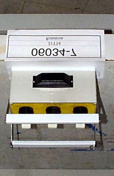
EGT854TX
Nov 30, 2000Remote Crane Control
Equipment Class
DXX - Part 15 Low Power Communication Device Transmitter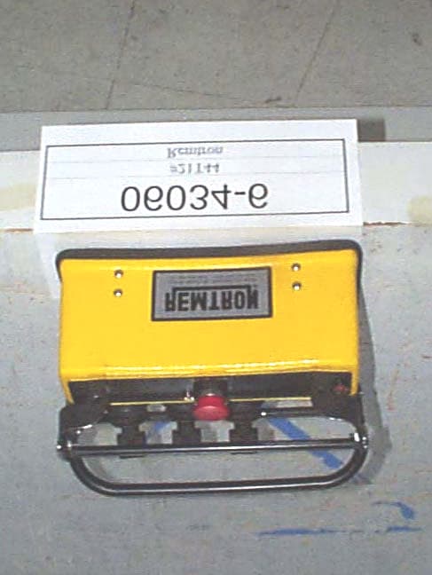
EGT844TX
Nov 26, 2000Remote Crane Control
Equipment Class
DXX - Part 15 Low Power Communication Device Transmitter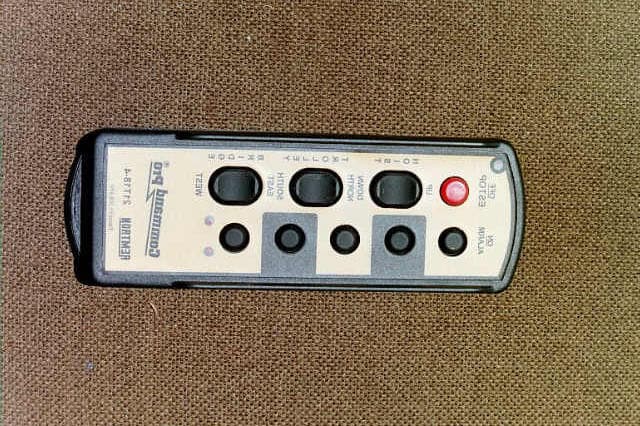
EGT818TX
Jul 09, 2000Wireless Controller
Equipment Class
DSC - Part 15 Security/Remote Control Transmitter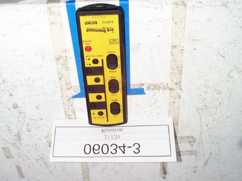
EGT820TX
Feb 16, 2000Wireless Remote Crane Transmitter
Equipment Class
DXX - Part 15 Low Power Communication Device Transmitter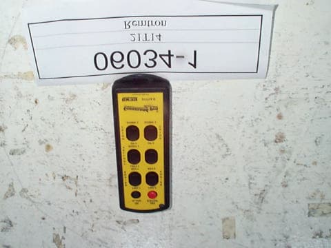
EGT814TX
Feb 15, 2000Wireless remote control for crane operation
Equipment Class
DXX - Part 15 Low Power Communication Device Transmitter