EHK-ETL615TXBaby Monitor Transmitter
Evenflo Company, Inc.
Click to zoom
Application Details
- Equipment Class
- DXX - Part 15 Low Power Communication Device Transmitter
- Date of Grant
- Apr 26, 2000
- Application Purpose
- Original Equipment
- Date of Application
- Apr 11, 2000
- Equipment Note
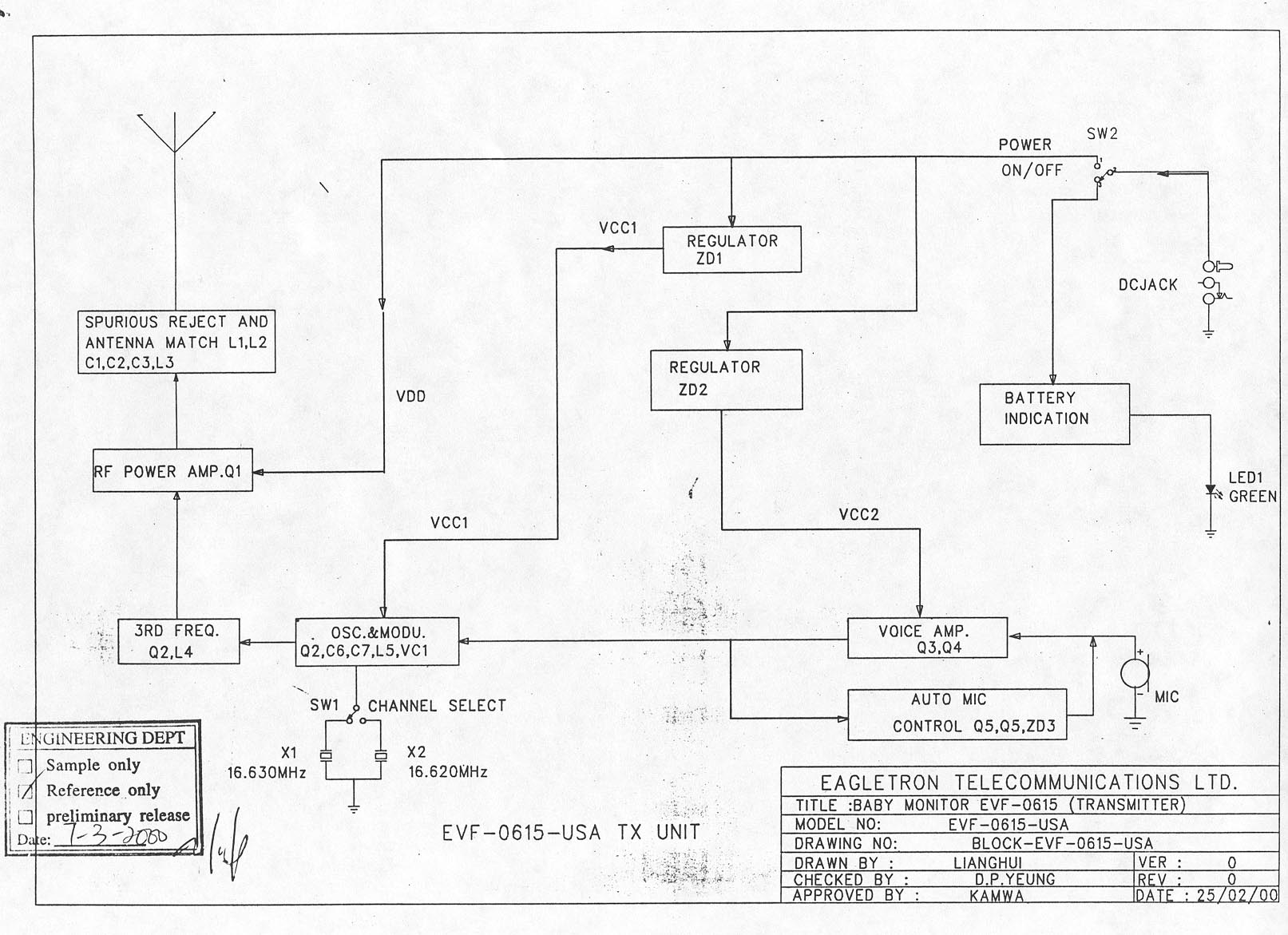
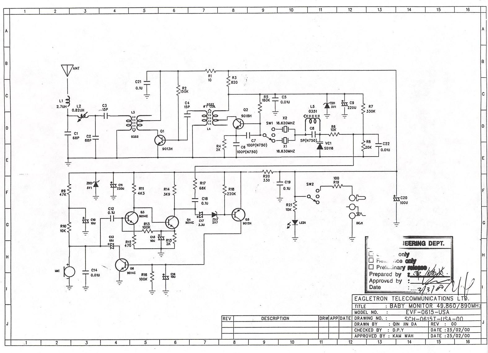
- Baby Monitor Transmitter
- Frequency Range
- 49.86000000 - 49.89000000
- Company
- Evenflo Company, Inc.
- Country
- United States
Documents & Files
Document Text
Text extracted from the exhibit documents filed with the FCC. Open a document above to read the original.
External Photos
Front View Back View Left Side View Right Side View AC Adapter
Internal Photos
Inside View Circuit Board – Component Side Circuit Board – Track Side
Test Report
ENGINEERING STATEMENT In Connection With EVENFLO COMPANY, INC. Model No. EVF-615 FCC ID: EHK-ETL615TX Hyak Laboratories, Inc. has been retained to perform radiated and conducted spurious measurements on the Evenflo Company Model EVF-615 transmitter in accordance with the provisions of Section 15.235 of the FCC rules, Part 15. I am an Electronics Engineer, a principal in the firm of Hyak Laboratories, Inc., Springfield, Virginia. My education and experience are a matter of record with the Federal Communications Commission, having submitted numerous applications for equipment authorization. All tests were made by me or under my supervision in accordance with the rules and regulations of the Federal Communications Commission. ______________________________ Rowland S. Johnson Dated: April 4, 2000 COMPLIANCE WITH SECTION 15.235 OF PART 15 The procedures of ANSI C63.4 (1992) were used. 15.235(a) The field strength of the radiation emission was measured and found to be less than 10,000 uV/M @ 3m within the 49.82 - 49.90 MHz band. A peak-reading, RMS calibrated, spectrum analyzer was used as the measuring device. (See data of Table 1.) A 100 kHz resolution bandwidth was used. 15.235(b) The field strength of all emissions removed by more than 10 kHz from the band edges did not exceed 500 uV/m @ 3 meters, (26 dBc) or the general limits of 15.209, whichever was the higher emission limit. All signals exceeding 20 uV/m @ 3 meters are reported in Table 1. The spectrum was scanned from 30 to 1000 MHz. Emissions were confined within a 20 kHz band centered on the carrier frequency. No provisions for an external input signal exist. (See Figure 1.) The antenna is permanently attached in the device. (See photographs.) 15.207(a) RF energy fed back into the power lines did not exceed 250 microvolts on any frequency between .45 to 30 MHz. (See plots of Figures 2 and 3.) DATA Radiated emissions were measured with the external AC power supply. Data in Table 1 is for worst-case emissions observed when the AC power module was used. Tables and Figures referenced above follow immediately after this page. Description of measurement procedures and test equipment used in the measurements follow the data pages. MEASUREMENT FACILITIES The Hyak Laboratories, Inc. measurement facility is currently listed as an acceptable site. 2 FIGURE 1a 85%, 2500 Hz Modulation OCCUPIED BANDWIDTH 2500 Hz Modulation FCC ID: EHK-ETL615TX FIGURE 1a 3 FIGURE 1b Loud Voice Modulation OCCUPIED BANDWIDTH Loud Voice Modulation FCC ID: EHK-ETL615TX FIGURE 1b 4 TABLE 1 RADIATED SPURIOUS EMISSIONS FCC Part 15 Frequency To Which Spurious Meter Antenna Field 1 Tuned Frequency Reading Factor Intensity FCC Limit dB to (MHz) (MHz) (dBm) (dB) uV/m @ 3m uV/m @ 3m Limit 49.860 49.859 -32.8 5.1 9226 10000 - .7 49.860 99.722 -93.2 11.2 18 150 - 19 49.860 149.583 -107.2 14.9 5* 150 - 29 49.860 199.444 -110.0 17.5 5* 150 - 29 49.860 249.305 -108.8 19.6 8* 200 - 28 49.860 299.166 -110.0 21.3 8* 200 - 28 49.860 349.027 -110.4 22.8 9* 200 - 27 49.860 398.888 -109.6 24.1 12* 200 - 25 49.860 448.749 -110.0 25.2 13* 200 - 24 49.860 498.610 -108.0 26.2 18* 200 - 21 49.890 49.891 - 32.4 5.1 9661 10000 - .3 49.890 99.782 - 92.0 11.2 20 150 - 17 49.890 149.673 -106.3 14.9 6* 150 - 28 49.890 199.564 -109.6 17.5 6* 150 - 29 49.890 249.455 -109.6 19.6 7* 200 - 29 49.890 299.346 -110.4 21.3 8* 200 - 28 49.890 349.237 -110.8 22.8 9* 200 - 27 49.890 399.128 -106.8 24.1 16* 200 - 22 49.890 449.019 -110.8 25.2 12* 200 - 25 49.890 498.910 -109.6 26.2 15* 200 - 22 Note 1: uV/m = Log -1dBu/m 20 dBu = dBm + antenna factor + 107 *Reference data, 20 dB or more below FCC limit. Occupied Bandwidth 49.860 f c -10 kHz (1) -40 dB to f c 92.3 - 15 49.860 f c +10 kHz (1) -45 dB to f c 51.9 - 20 Frequency range of 30 to 499.0 MHz was scanned. No signals exceeded FCC limits and all signals greater than 20 uV/m @ 3m are shown above. (1) From Figure 1a RADIATED FIELD INTENSITY FCC ID: EHK-ETL615TX TABLE 1 5 FIGURE 2 LINE CONDUCTED EMISSIONS FCC ID: EHK-ETL615TX FIGURE 2 (Left LISN) 6 FIGURE 3 LINE CONDUCTED EMISSIONS FCC ID: EHK-ETL615TX FIGURE 3 (Right LISN) 7 PROCEDURES, EMISSION BANDWIDTH Measurement of emission bandwidth was made with a 2500 Hz tone at a sufficient level to produce 85% of limiting modulation. The input signal was coupled directly to the audio input stage of the device. A Tektronix 494P spectrum analyzer was used; input audio signal was from a IEC F-47 function generator; audio level was determined with a Fluke 8920A TRMS voltmeter; modulation was measured with a Boonton 8220 modulation monitor. A second plot was made with loud voice signal. PROCEDURES, RADIATED SPURIOUS EMISSIONS Procedures of ANSI 63.4 - 1992 were followed. The field strength of the radiated emissions from the device was measured at a distance of 3 meters. The spectrum was scanned from 30 MHz to the tenth harmonic using a TEK 494P spectrum analyzer and HP 8447D low-noise preamplifier. Measurement procedure included recording the worst-case field strength for receiving test antenna polarization, test antenna height variation from 1 meter to 3 meters and test sample antenna in both vertical and horizontal plane. The test sample was placed on a rotatable 80 cm high wooden stand. The receiving antenna, placed 3 meters from the test sample, was a Eaton/Singer DM-105 calibrated dipole set. Power supply was the 9 volt plug-in transformer supplied with the test sample. The test sample was measured in the bottom down, face down, and side down positions. The spectrum was checked from 30 to 499 MHz. All emissions not reported were less than 20 uV/m @ 3m. Tabulation of the measurements are shown in Table 1. 8 PROCEDURES, AC LINE CONDUCTED SPURIOUS Power line conducted spurious were measured from .45 to 30 MHz using an IEEE 213 line impedance stabilization network, (LISN), modified for a 50 uH network. The device under test was placed on a ground plane, per ANSI 63.4 (1992), on a 80 cm high wooden stand centered in the …
Text truncated - open the document above for the full version.
Contact Information
Applicant
Thomas A Sparno(Executive Vice President, Gen Counsel & Secy.)
Technical Contact
Hyak Laboratories, Inc.Rowland S Johnson
[email protected](703) 451-1188
7011 Calamo St., Suite 107 · Springfield, Virginia · United States
Non-Technical Contact
Hyak Laboratories, Inc.Georgia Hall
[email protected](703) 451-1188
Test Firm
Hyak Laboratories, Inc.Rowland Johnson
703-451-1188
Technical Specifications
| # | Rule Parts | Frequency Range | Power Output |
|---|---|---|---|
| 1 | 15C | 49.86 MHz - 49.89 MHz | - |
Other Applications from Evenflo Company, Inc.
EHK315463GMMPGATE
Feb 04, 2006Remote Control Door Gate
Equipment Class
CRR - Superregenerative Receiver
EHK315463WMHFGATE
Feb 04, 2006Wall Mounted Remote Control
Equipment Class
DSC - Part 15 Security/Remote Control Transmitter
EHK315463GMOPGATE
Feb 04, 2006Remote Control Door gate
Equipment Class
CRR - Superregenerative Receiver
EHK315463RHFGATE
Feb 04, 2006Removable Remote Control
Equipment Class
DSC - Part 15 Security/Remote Control Transmitter
EHK900646TTRIA
Jul 02, 2004900MHz Transceiver
Equipment Class
DXT - Part 15 Low Power Transceiver, Rx Verified