EILPGRM-AGABOVE GROUND POOL ALARM
PBM Industries Inc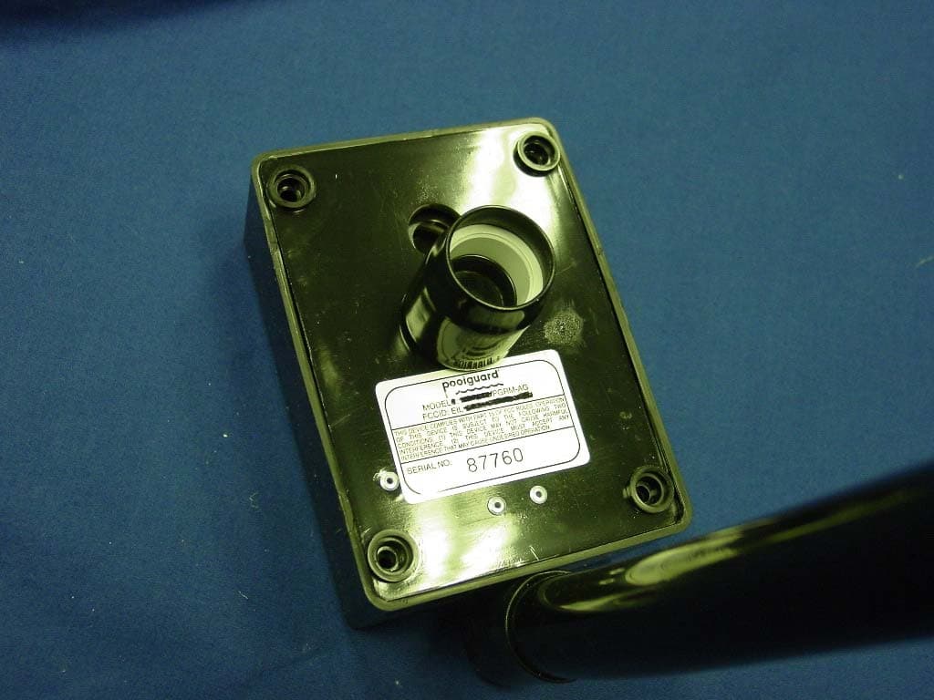
Click to zoom
Application Details
- Equipment Class
- DSC - Part 15 Security/Remote Control Transmitter
- Date of Grant
- Jan 14, 2008
- Application Purpose
- Original Equipment
- Date of Application
- Jan 10, 2008
- Equipment Note
- ABOVE GROUND POOL ALARM
- Frequency Range
- 433.92000000 - 433.92000000
- Company
- PBM Industries Inc
- Country
- United States
Documents & Files
Document Text
Text extracted from the exhibit documents filed with the FCC. Open a document above to read the original.
Users Manual
IMPORTANT HELPFUL HINTS & TIPS This product has been designed to aid in the detection of unwanted intrusions into unsupervised pools. POOLGUARD IS A SAFETY ALARM SYSTEM AND NOT A LIFE SAVING DEVICE. “This device is not intended to replace any other safety consideration - i.e., adult supervision, lifeguards, fences, gates, pool covers, locks, etc., and some devices may not detect gradual entry.” OPERATING INSTRUCTIONS MANUAL MEETS ASTM SAFETY STANDARD FOR POOL ALARMS ABOVE GROUND POOL ALARM READ THOROUGHLY BEFORE USING ALARM OUT OF POOL OFF POSITION IN-POOL ON POSITION 85dB Horn at 10 Feet MEETS ASTM F2208 2 GENERAL POOLGUARD is the result of quality design and manufacturing techniques that are a standard at PBM Industries, Inc.; a company dedicated to high quality products. POOLGUARD is a result of that dedication and we guarantee and stand behind the POOLGUARD alarm system. POOLGUARD is an electronic monitoring system that automatically sounds an alarm when children or pets fall into your unsupervised pool. POOLGUARD is a portable, self-contained, lightweight unit that is safe and simple to operate. Simply place POOLGUARD on the top rail of the pool. Entry into the pool will be detected by the unit’s electronic sensor, triggering a loud pulsating alarm and an internal RF transmitter. A remote receiver unit will receive the transmitted signal which sounds an alarm within the home. INSPECTION POOLGUARD is packaged in a shipping carton that minimizes the chance of damage due to handling. Check for damage and confirm that the contents of the carton include the following items: • POOLGUARD ALARM • TWO QUICK SNAP POSTS & HARDWARE • REMOTE RECEIVER AND POWER SUPPLY • OPERATING INSTRUCTION MANUAL • WARRANTY AND SERVICE CARDS If an item is missing, contact either the place of purchase or PBM Industries, Inc. for replacement. 3 CARE AND HANDLING POOLGUARD is constructed from sturdy plastic to withstand the adverse moisture environment of a swimming pool. Care needs to be taken when handling your alarm and be sure to remove the alarm when the pool is being used. If the alarm accidentally falls into your pool, remove it immediately and drain the water from it. Take the alarm apart as indicated in the Battery Installation/Replacement and remove the battery. Remove all excess water from inside the unit and battery, and the circuit board area with a paper towel or cloth. Completely test unit before each use. Remember to always remove the alarm from the pool before swimming. INSTALLING YOUR ALARM RESET/SLEEP SWITCH. (See Figure 1) RESET:When the pool unit is installed in the pool and the horn is sounding; press the reset/sleep switch once to silence the alarm. SLEEP MODE:When the pool unit is removed from the pool and the horn is sounding; press and hold the reset/sleep switch for 3 seconds to silence the alarm. The pool unit will automatically wake up when it is installed into the pool. THEPOOL UNIT WILL NOT GOT INTO SLEEP MODE ONCE IT IS INSTALLED IN THE POOL. SILENT INSTALLATION AND REMOVAL FEATURE • The poolguard system will sound an alarm (Horn will sound) when you install or remove the pool unit from your pool. If you would like the poolguard system not to sound an alarm (Horn will not sound) when you install or remove the pool unit from your pool, follow the directions below. 1.SILENT INSTALLATION (HORN WILL NOT SOUND) • Press and hold the reset/sleep switch for 3 seconds, until you hear the pool units horn chirp. Release the reset/sleep switch, you now have 15 seconds to install the pool unit into your pool without the horn sounding. POOLGUARD WILL INSTANTLY BE MONITORING YOUR POOL FOR AN INTRUSION. (Continued on next page) 4 SILENTINSTALLATION AND REMOVAL FEATURE (Cont.) 2.SILENT REMOVAL (HORN WILL NOT SOUND) •Before removing the pool unit from your pool. Press and hold the reset/sleep switch for 3 seconds, until you hear the pool units horn chirp. Release the reset/sleep switch, you now have 5 seconds to remove the pool unit from your pool without the horn sounding. IMPORTANT: THIS DOES NOT TURN POOLGUARD OFF, IF THE POOL UNIT IS NOT REMOVED IT WILL CONTINUE TO MONITOR YOUR POOL FOR AN INTRUSION. 3. POOLGUARD HAS DESIGNED THIS FEATURE FOR “ONLY” THOSE WHO HAVE THE RESPONSIBILITY OF INSTALLING OR REMOVING THE ALARM FROM YOUR POOL! BATTERY INSTALLATION / REPLACEMENT (Battery not included) POOLGUARD is powered by a standard 9-volt alkaline battery. To install or replace battery: • IMPORTANT: WHEN A 9V BATTERY IS FIRST INSTALLED IN THE POOL UNIT, THE HORN WILL SOUND. TO SILENCE THE ALARM PRESS AND HOLD THE RESET/SLEEP SWITCH FOR 3 SECONDS. THIS PLACES THE POOL UNIT IN SLEEP MODE. THE POOL UNIT WILL AUTOMATICALLY WAKE UP WHEN IT IS INSTALLED INTO THE POOL. • Remove the four screws from the back of the alarm, refer to Figure 1. • Install new battery by attaching battery snap to battery terminals; place in battery holder on inside of back plate according to the bat- tery placement decal. • Replace the back plate and four screws. • To prevent possible damage, battery should be removed whenever storing the alarm for an extended period of time. LOW BATTERY FUNCTION The POOL UNIT ANDTHE REMOTE RECEIVER will beep once approximately every 20 seconds to alert you that the battery is low in the pool unit and needs to be replaced. IMPORTANT POOLGUARD may not function properly if your pool’s water level is not maintained within the required levels of your alarm. Also, the unit may not operate effectively while certain types of automatic pool cleaners are in operation. ABOVE GROUND POOL ALARM RESET/SLEEP HORN 85db at 10 feet PLACEMENT IN YOUR POOL POOLGUARD automatically compensates for variations in pool levels within the unit’s operating range. The unit utilizes a sensor which projects into the water and is designed to operate in most pools with an in-wall skimmer. The sensor cannot be less than 3 inches, (See Figure 1) and not more than 8 inches into the water. FIGURE 1 5 (Continued on next page) 6 PLACEMEN…
Text truncated - open the document above for the full version.
Cover Letter(s)
RF LABORATORIES, INC 1412 Center Avenue • Oostburg, Wisconsin 53070 (920) 564-2700 • FAX (920) 564-1027 • e-mail: [email protected] Federal Communications Commission Authorization and Evaluation Division Confidentiality Request regarding application for certification of FCC ID: EILPGRM-AG. Pursuant to Sections 0.457 and 0.459 of the Commission’s Rules, we hereby request confidential treatment of information accompanying this application as outlined below: Schematic.pdf Block Diagram.pdf Operational Description.doc The above materials contain trade secrets and proprietary information not customarily released to the public. The public disclosure of these materials may be harmful to the applicant and provide unjustified benefits to its competitors. Pursuant to DA 04-1705 June 15, 2004 of the Commission’s public notice, we also request temporary confidential treatment of information accompanying this application as outlined below: Internal Photos External Photos pdf-agman.pdf The applicant understands that pursuant to Section 0.457 of the Rules, disclosure of this application and all accompanying documentation will not be made before the date of the Grant for this application. Sincerely, David J. Zima Attached: Copy of FCC Confidentiality Policy
External Photos
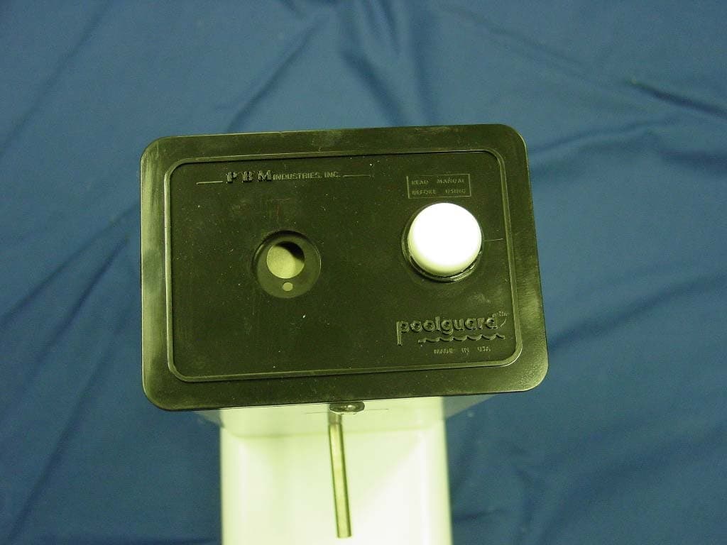
PBM INDUSTRIES, INC. FCC ID: EILPGRM-AG EXTERNAL PHOTOS
Internal Photos
PBM INDUSTRIES, INC. FCC ID: EILPGRM-AG INTERNAL PHOTOS
Test Report
APPLICANT: PBM INDUSTRIES, INC. FCC ID: EILPGRM-AG REPORT: P\PBM_EIL\3873UT7\3873UT7TestReport.doc Page 2 of 18 mdea 09.20.2007 FCC PART 15.231 TEST REPORT LOW POWER UNLICENSED TRANSMITTER Applicant PBM INDUSTRIES, INC. Address 1150 WEST JFG DRIVE NORTH VERNON IN 47265 USA FCC ID EILPGRM-AG Product Description ABOVE GROUD POOL ALARM Date Sample Received 12/19/2007 Date Tested 12/28/2007 Tested By NAM NGUYEN Approved By MARIO DE ARANZETA Timco Report No. 3873UT7TestReport.doc Test Results Pass Fail THE ATTACHED REPORT SHALL NOT BE REPRODUCED EXCEPT IN FULL WITHOUT THE WRITTEN APPROVAL OF TIMCO ENGINEERING, INC. 849 NW STATE ROAD 45 NEWBERRY, FL 32669 USA PH: 888.472.2424 OR 352.472.5500 FAX: 352.472.2030 EMAIL: [email protected] HTTP: //WWW.TIMCOENGR.COM Certificate # 0955-01 APPLICANT: PBM INDUSTRIES, INC. FCC ID: EILPGRM-AG REPORT: P\PBM_EIL\3873UT7\3873UT7TestReport.doc Page 3 of 18 mdea 09.20.2007 TABLE OF CONTENTS GENERAL REMARKS ....................................................................................................4 REPORT SUMMARY ......................................................................................................5 TEST ENVIRONMENT....................................................................................................5 TEST SETUP .................................................................................................................5 DUT SPECIFICATION ....................................................................................................6 MANUFACTURE DECLARATION OF COMPLIANCE WITH PART 15.231(A)......................7 TEST EQUIPMENT LIST ................................................................................................8 TEST PROCEDURES .....................................................................................................9 RADIATION INTERFERENCE .......................................................................................10 CALCULATION OF DUTY CYCLE .................................................................................12 OCCUPIED BANDWIDTH.............................................................................................17 POWER LINE CONDUCTED INTERFERENCE ..............................................................18 APPLICANT: PBM INDUSTRIES, INC. FCC ID: EILPGRM-AG REPORT: P\PBM_EIL\3873UT7\3873UT7TestReport.doc Page 4 of 18 mdea 09.20.2007 GENERAL REMARKS The attached report shall not be reproduced except in full without the written permission of Timco Engineering Inc. The test results only relate to the item tested. Summary The device under test does: fulfill the general approval requirements as identified in this test report not fulfill the general approval requirements as identified in this test report Attestations This equipment has been tested in accordance with the standards identified in this test report. To the best of my knowledge and belief, these tests were performed using the measurement procedures described in this report. All instrumentation and accessories used to test products for compliance to the indicated standards are calibrated regularly in accordance with ISO 17025 requirements. Testing Certificate # 0955-01 I attest that the necessary measurements were made, under my supervision, at: Timco Engineering Inc. 849 NW State Road 45 Newberry, Fl 32669 Authorized Signatory Name: Mario de Aranzeta C.E.T. Compliance Engineer/ Lab. Supervisor Date: 1/8/08 APPLICANT: PBM INDUSTRIES, INC. FCC ID: EILPGRM-AG REPORT: P\PBM_EIL\3873UT7\3873UT7TestReport.doc Page 5 of 18 mdea 09.20.2007 REPORT SUMMARY Applicable Rule(s) FCC Pt 15.231, Pt 15.209, Pt 15.207, ANSI C63.4: 2003 TEST ENVIRONMENT Test Facility The test sites are located at 849 NW State Road 45 Newberry, FL 32669 USA. Test Condition: Temperature: 26ºC Relative humidity: 50% TEST SETUP Test Exercise (e.g software description, test signal, etc.): The DUT was placed in continuous transmit mode of operation. Deviation from the standard(s) No deviation from the standard(s) Modification to the DUT: No modification was made to the DUT. Supporting Peripheral Equipment Not applicable. The device is a stand-alone remote control radio. APPLICANT: PBM INDUSTRIES, INC. FCC ID: EILPGRM-AG REPORT: P\PBM_EIL\3873UT7\3873UT7TestReport.doc Page 6 of 18 mdea 09.20.2007 DUT SPECIFICATION Applicant PBM INDUSTRIES, INC. Description ABOVE GROUD POOL ALARM FCC ID EILPGRM-AG Model Number PGRM-AG Frequency Range 433.9-433.9 MHz 110–120Vac/50– 60Hz DC Power DUT Power Source Battery Operated Exclusively Test Item Prototype Pre-Production Production Type of Equipment Fixed Mobile Portable APPLICANT: PBM INDUSTRIES, INC. FCC ID: EILPGRM-AG REPORT: P\PBM_EIL\3873UT7\3873UT7TestReport.doc Page 7 of 18 mdea 09.20.2007 MANUFACTURE DECLARATION OF COMPLIANCE WITH PART 15.231(A) Item Description Yes No 1 Does this device transmit a signal that is only used to control another device? X 2 Does this device send data with this control signal? X 3 Does this device send data? Data is, things like: temperature, wind direction, fluid amount, rate of flow, etc. X 4 Does this device transmit continuously or automatically? X 5 If manually operated does this device stop transmitting within 5 seconds of releasing the button? X 6 If automatically operated does it deactivate 5 seconds after activation? N/A N/A 7 Does it transmit at regular predetermined intervals? X Does it poll or send supervisory information? X 8 If yes does it do a system integrity check? How often? X Is this a fire, security or safety of life device? X 9 If YES does the device stop transmitting after the alarm condition is satisfied? X Duty cycle: Maximum on-time? 10ms If YES, on-time in 100 ms? If Other, please specify here X 10 On time in 11 Modulation technique: Please specify the modulation of the test sample, FM, or AFSK, or FSK, or on-off keying, or others? OOK APPLICANT: PBM INDUSTRIES, INC. FCC ID: EILPGRM-AG REPORT: P\PBM_EIL\3873UT7\3873UT7TestReport.doc Page…
Text truncated - open the document above for the full version.
Contact Information
Applicant
Scott Hines(Electronic Engineer)
Test Firm
Timco Engineering, Inc.Sid Sanders
Technical Specifications
| # | Rule Parts | Frequency Range | Power Output |
|---|---|---|---|
| 1 | 15.231 | 433.92 MHz - 433.92 MHz | - |
Other Applications from PBM Industries Inc
EILPGRM-2
Jan 14, 2008IN GROUND POOL ALARM
Equipment Class
DSC - Part 15 Security/Remote Control Transmitter
EIL-POOLGUARD-PBM
Feb 24, 2003Pool Alarm Transmitter
Equipment Class
DSC - Part 15 Security/Remote Control TransmitterEIL58J-LXRM-SXRM
May 01, 1985DXX - Part 15 Low Power Communication Device Transmitter
Equipment Class
DXX - Part 15 Low Power Communication Device TransmitterEIL58J-RM01
Mar 26, 1985CYY - Communications Receiver used w/Pt 15 Transmitter
Equipment Class
CYY - Communications Receiver used w/Pt 15 Transmitter