EMW025288900MHz Cordless Telephone
KCL Technology Ltd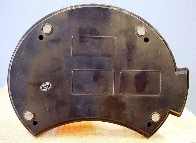
Click to zoom
Application Details
- Equipment Class
- DXX - Part 15 Low Power Communication Device Transmitter
- Date of Grant
- Jul 23, 2001
- Application Purpose
- Original Equipment
- Date of Application
- Jul 23, 2001
- Equipment Note
- 900MHz Cordless Telephone
- Frequency Range
- 925.00000000 - 928.00000000
- Company
- KCL Technology Ltd
- Country
- Hong Kong
Documents & Files
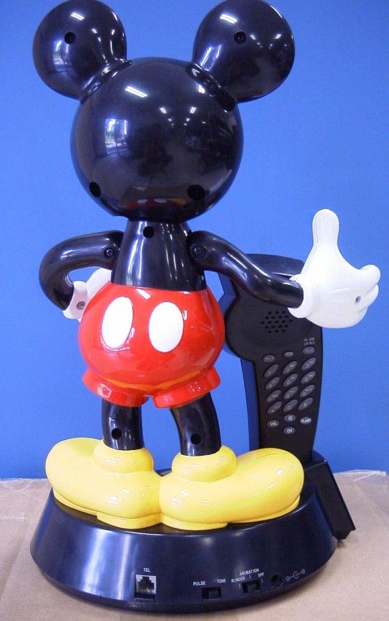
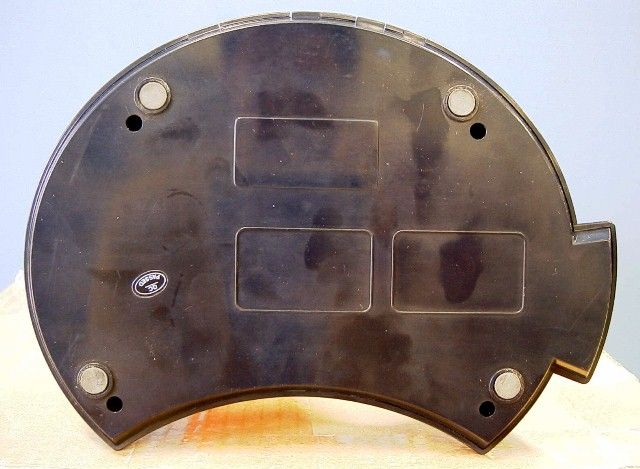

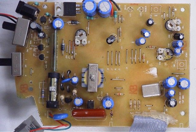
Document Text
Text extracted from the exhibit documents filed with the FCC. Open a document above to read the original.
ID Label/Location Info
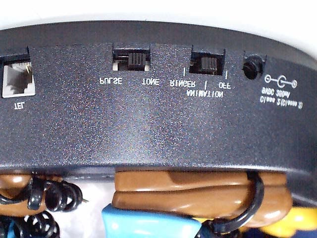
KCL Electronics Co. Ltd. KCL INDUSTRIAL BUILDING, HUANG NI TANG, CHANGPING, DONGGUAN, GUANGDONG, CHINA. TEL: 86 769 339 2751 FAX: 86 769 339 2643 EXHIBIT H MODEL: Mickey Mouse Animated Talking Cordless Phone. FCC LABEL TELEMANIA FCC ID : EMW025288 MADE IN CHINA FCC ID : EMW025288 TELEMANIA MODEL : MICKEY MOUSE ANIMATED TALKING CORDLESS PHONE THIS UNIT COMPLIES WITH FCC PART 68 AS OF DATE OF MANUFACTURE FCC REGN # : RINGER EQUIVALENCE : KCL TECHNOLOGY LTD . U.S.O.C: RJ11C HAC 0501 MADE IN CHINA TM TM KCL ELECTRONICS CO. LTD. K.K. Szeto Manufacturing Manager Date: May 10,2001
Operational Description
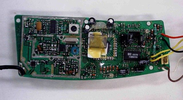
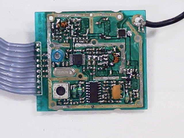
KCL Electronics Co. Ltd. KCL INDUSTRIAL BUILDING, HUANG NI TANG, CHANGPING, DONGGUAN, GUANGDONG, CHINA. TEL: 86 769 339 2751 FAX: 86 769 339 2643 MICKEY MOUSE ANIMATED TALKING CORDLESS PHONE CIRCUIT DESCRIPATION A. Micro Audio Transmitting Handset Unit section: The handset microphone signals pass through R52, C92 into COMPANDOR IC U4/KA8507B pin8 , outputs from pin3 after amplified and compressed, then into the Low Pass Filter consisted by R55,C86,C88,R54 and internal OP Amp. in U4. The audio signals then are to be modulated at TX VCO where RF Transistor NE88130/ Q4 functions as two issues: oscillation at center frequency 927MHZ/2 and second is a double frequency conversion. The TX VCO is controlled by Programmed digital PLL:U2/M64082 which PD signals are generated and output from Pin9 and passed through LP Filter consisted by C28,R14,C27,C29,R18,and RC31. The modulated carrier wave passes through C17,C16 into TXPOWER amplifier NE88130/Q3, is selected by DUPLEXER F1, then bypassed by L0,C1 and lastly transmitted through ANTENNA . Base unit section: After the base unit antenna receives the carrier wave current signal, the modulated carrier is sent into the Base of RF Transistor NE88130/Q1 selected by DUPLEXER F1/SFX033, Q1 serves as Low Noise Amplifier for the input weak carrier signal. Q2/ BF998R , L1,C10,R6,C9,C7,R5 function together as a Mixer which the Local frequency signal is produced by another VCO, The RX VCO consisted by Q5,L5,VD2,C38~C43 is controlled by U2/PLL IC M64082 to modify the oscillator frequency so as to meet the request of different channel change from Microprocessor unit U3/KS57P5307 program. 1 ST IF 10.7Mhz signal, that production come from mixing result, will go into the base of IF amplifier Q6/2SC1623L6 after selected by F2/10.7Mhz Filter, then pass through C12 and into IF RECEIVER IC U1 pin 16. The demodulated audio signal will be output from Pin11 of U1 after the 1 ST IF signal is amplified , limited and converted to 2 ND IF 450KHZ signal ,further the 2 ND IF signal is descriminated all these happen at the internal of U1 IC. The audio signal from U1 pin11 output will be sent into COMPANDOR IC/U4 pin15 and then delivered from U4/Pin19, after amplified, expended internally by U4. The expended audio signal will be amplified by Q11, and then be sent into the Tel-line passed through Transformer T2 second side, coupled to primary side, and through Polarity Protection circuitry D5,D6,D7,D8, then the RL1 contact. B. Audio receiving. Base Unit section: KCL Electronics Co. Ltd. KCL INDUSTRIAL BUILDING, HUANG NI TANG, CHANGPING, DONGGUAN, GUANGDONG, CHINA. TEL: 86 769 339 2751 FAX: 86 769 339 2643 Received audio signals from Tel-line, pass through Z1,R97, F3, RL1 to Polarity Protection circuitry D5,D6,D7,D8, then are coupled to Transformer T2 second side, then pass through C92,R104,R56,C95,C96,C97,R57into COMPRESSOR IC U4 pin 8 . The audio signal will output from pin3 of U4 after amplified, compressed internally by U4, then pass through the filter consisted by R59,C102,R60,C105, and the OP AMP. In U4 Pin1,2 into TX VCO circuit and are modulated here. Q4, together with L4, VD1, C20~C26 make the function as TX VCO, which the center oscillation frequency is modified by PLL IC U2/M64082 through its Pin9 according the requirement of Channel changing and setup from Microprocessor unit U3/KS57P5308 program. The RF transistor Q4 also serves as double frequency converter which convert the TX Channel Fre/2 into TX Channel. The carrier wave will go to TXPOWER AMPLIFIER Q3, then pass through C14 to DUPLEXER F1, After selected by F1, The carrier signal is transmitted out bypass L0, C1 and passed through ANTENNA. HANDSET section: The handset antenna receives the carrier wave, which will pass through L0,C1 and into DUPLEXER F1, After amplified by the high frequency AMPLIFIER Q1, the carrier is sent into MIXER ,Q2 together with C10, L1, C9,C7,R5,R6 consisted by. The Local frequency signal which need to be into MIXER is produced by RX VCO, consisted by Q5,C34, C38~C43,VD2, Its working is almost same as TX VCO. There are almost same as the IF receiving circuit description as BASE UNIT section ,The expended audio output signal from COMPANDOR U4 pin 19 at HANDSET section, passes through C109,R89,C110 into U5 pin 6 of U5 , then is supplied to the RECEIVER after filtered by U5-B. C. Data transmit and receive The all data signals implicated all key operation at HANDSET are output from MCU U3 pin 14 , then pass through C113,R53 into TX VCO circuit Q4, The signals are modulated here, The following process is same as A. Section The Base unit data receiving is same as A. section too, The demodulated RX DATA output from Pin9 of U1 are filtered and shaped by U5-C port, then sent into Pin19 of U3/KS57P5308.The Microprocessor Unit will make correct operation after it receives correct data order. The all data signals implicated all order, such as Ringing, Paging output from pin14 of U3 of BASE UNIT, pass through R50,C91,R16 to VCO circuit Q4, The signals are modulated here, The following process is same as B. Section. The handset data receiving is same as B. Section too. The demodulated RX DATA signals output from Pin9 of U1 are filtered and shaped by U5-C and KCL Electronics Co. Ltd. KCL INDUSTRIAL BUILDING, HUANG NI TANG, CHANGPING, DONGGUAN, GUANGDONG, CHINA. TEL: 86 769 339 2751 FAX: 86 769 339 2643 Q17, then sent into Pin25 of U3/KS57P5308. D. Mickey mouse operation At Base unit, if Ringer select switch is selected at ANIMATATION site, its means that SW4-A is switched to SHOW at BASE MAIN SCHEMATIC, When income call happens,U3/KS57P5308 can detect the ringing signal by detecting its Pin22 input level status that produced due to Optic coupler operation when Ringer trigging happens, then U3 will give off buzzer trigging signals from its Pin29 ,The buzzer signal will be filtered and used as to trigger for Pin3 of U8 /W581**, so U8 can output melody from Pin10 to Q13 Amplifier ,and then driver SPEAKER.,…
Text truncated - open the document above for the full version.
Test Report
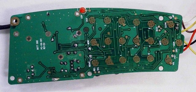
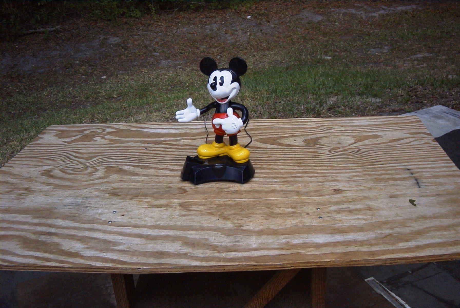
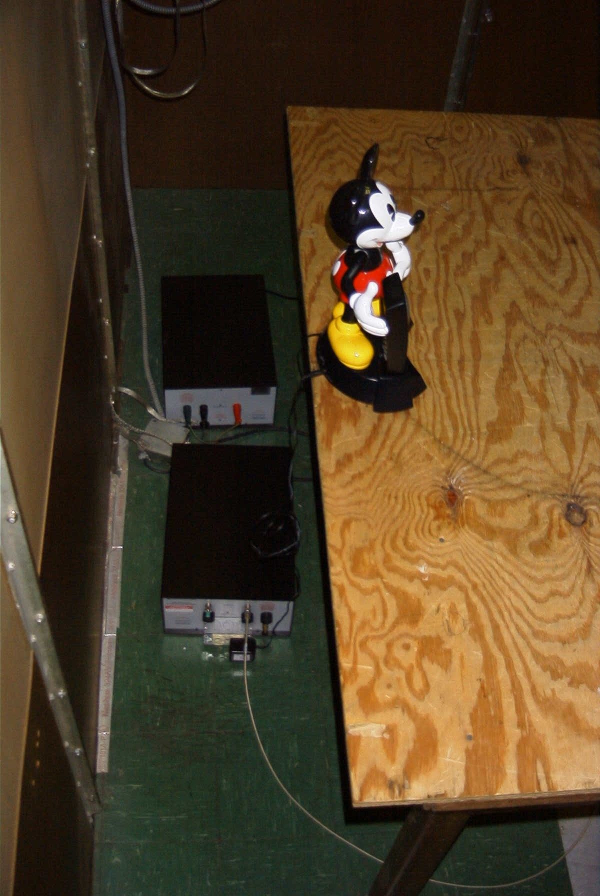
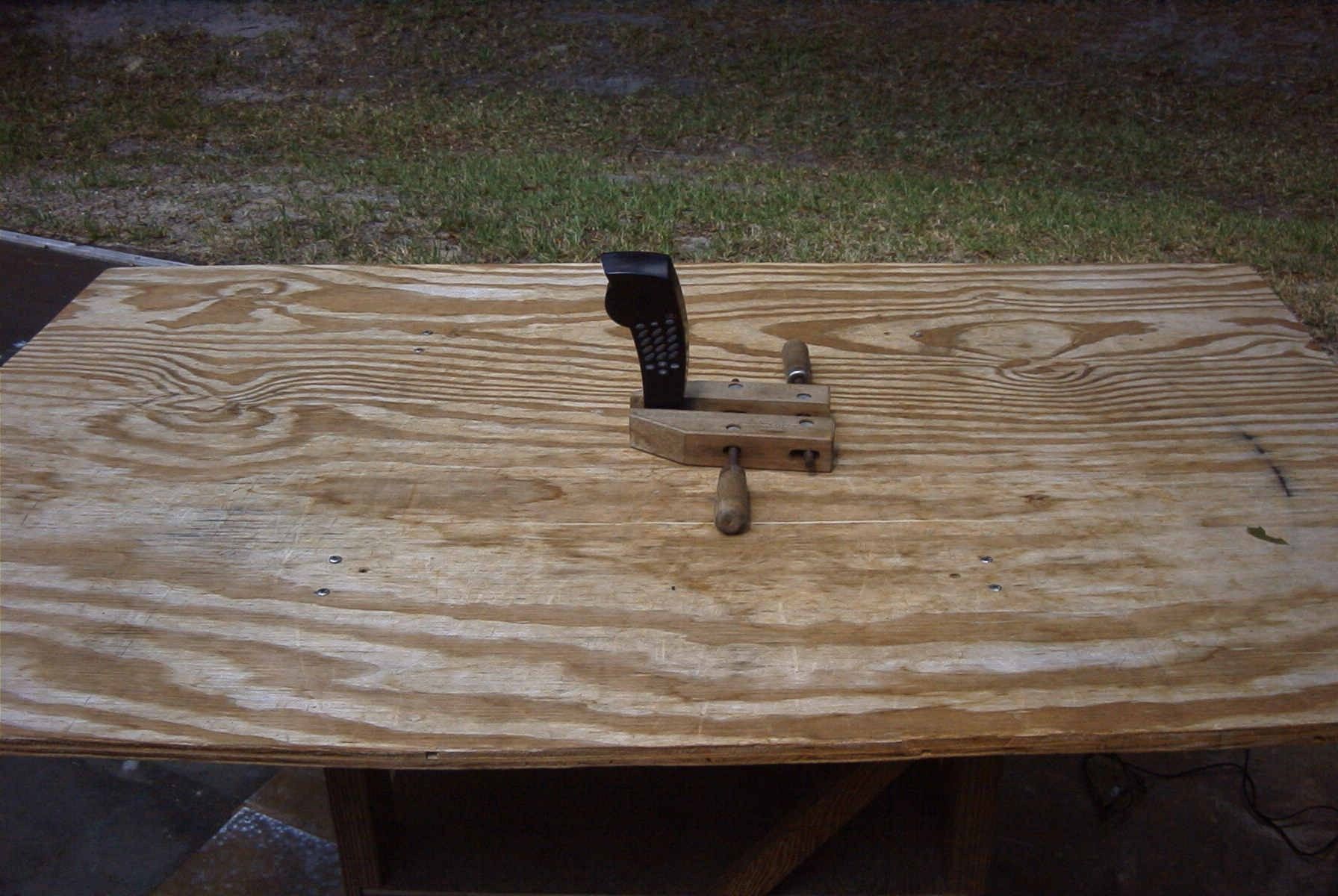
APPLICANT: KCL TECHNOLOGY LTD. FCC ID: EMW025288 TABLE OF CONTENTS TEST REPORT CONTAINING: PAGE 1........15.214(d) - SECURITY CODING INFORMATION AND TEST PROC. PAGE 2........TEST PROCEDURE CONTINUED PAGE 3........RADIATION INTERFERENCE TEST DATA - BASE PAGE 4........RADIATION INTERFERENCE TEST DATA – HANDSET PAGE 5........OCCUPIED BANDWIDTH TEST DATA PAGE 6A-6B....OCCUPIED BANDWIDTH PLOTS PAGE 7........POWERLINE CONDUCTED TEST DATA PAGE 8A-8B....POWERLINE CONDUCTED PLOTS EXHIBITS CONTAINING: EXHIBIT 1...........MODIFICATION LETTER EXHIBIT 2A-2B.......BLOCK DIAGRAM - BASE EXHIBIT 3...........BLOCK DIAGRAM - HANDSET EXHIBIT 4A-4C.......SCHEMATIC - BASE MAIN EXHIBIT 5A-5B.......SCHEMATIC - HANDSET EXHIBIT 6...........FCC ID LABEL SAMPLES EXHIBIT 7...........SKETCH OF FCC ID LABEL LOCATION - BASE EXHIBIT 8...........SKETCH OF FCC ID LABEL LOCATION – HANDSET EXHIBIT 9...........EXTERNAL PHOTO FRONT VIEW TELEPHONE SET EXHIBIT 10..........EXTERNAL PHOTO REAR VIEW BASE AND HANDSET EXHIBIT 11..........EXTERNAL PHOTO BOTTOM VIEW BASE EXHIBIT 12-13.......INTERNAL PHOTO – COMPONENT BASE EXHIBIT 14-15.......INTERNAL PHOTO – COPPER BASE EXHIBIT 16..........INTERNAL PHOTO – COMPONENT HANDSET EXHIBIT 17..........INTERNAL PHOTO – COPPER HANDSET EXHIBIT 18A-18B.....TEST SETUP PHOTOGRAPH – RADIATED EXHIBIT 19..........TEST SETUP PHOTOGRAPH – CONDUCTED EXHIBIT 20..........CIRCUIT DESCRIPTION EXHIBIT 21..........INSTRUCTION MANUAL EXHIBIT 22..........SECURITY CODING INFORMATION APPLICANT: KCL TECHNOLOGY LTD. FCC ID: EMW025288 REPORT #: K\KCL\556Z-1\556Z-1TestReport.doc PAGE: TABLE OF CONTENTS APPLICANT: KCL TECHNOLOGY LTD. FCC ID: EMW025288 SECURITY CODING INFORMATION 15.214(d) - THIS DEVICE COMPLIES WITH THE SECURITY CODE REQUIRE- MENTS OF 15.214(d)(1)(2) AND (3) BY MEANS OF THE FOLLOWING: TEST EQUIPMENT LIST 1._X_Spectrum Analyzer: HP 8566B-Opt 462, S/N 3138A07786, w/ preselector HP 85685A, S/N 3221A01400, Quasi-Peak Adapter HP 8565OA, S/N 3303A01690 & Preamplifier HP 8449B-OPT H02, S/N 3008A00372 2._X_Biconnical Antenna: Eaton Model 94455-1, S/N 1057, 3.___Biconnical Antenna: Electro-Metrics Model BIA-25, S/N 1171 4._X_Log-Periodic Antenna: Electro-Metrics Model EM-6950, S/N 632 5.___Log-Periodic Antenna: Electro-Metrics Model LPA-30, S/N 409 6.___Double-Ridged Horn Antenna: Electro-Metrics Model RGA-180, 1-18 GHz, S/N 2319 7.___18-26.3GHz Systron Donner Standard Gain Horn #DBE-520-20 8.___Horn 40-60GHz: ATM Part #19-443-6R 9.___Line Impedance Stabilization Network: Electro-Metrics Model EM-7820, w/NEMA Adapter S/N 2682 10.___Temperature Chamber: Tenney Engineering Model TTRC, S/N 11717-7 11.___Frequency Counter: HP Model 5385A, S/N 3242A07460 12.___Peak Power Meter: HP Model 8900C, S/N 2131A00545, 13._X_Open Area Test Site #1-3meters 14.___Signal Generator: HP 8640B, S/N 2308A21464 Cal. 11/21/00 15.___Signal Generator: HP 8614A, S/N 2015A07428 16.___Passive Loop Antenna: EMCO Model 6512, 9KHz to 30MHz, S/N 9706-1211 17.___Dipole Antenna Kit: Electro-Metrics Model TDA-30/1-4, S/N 153 18.___AC Voltmeter: HP Model 400FL, S/N 2213A14499 19.___Digital Multimeter: Fluke Model 8012A, S/N 4810047 20.___Digital Multimeter: Fluke Model 77, S/N 43850817 21.___Oscilloscope: Tektronix Model 2230, S/N 300572 APPLICANT: KCL TECHNOLOGY LTD. FCC ID: EMW025288 REPORT #: K\KCL\556Z-1\556Z-1TestReport.doc PAGE: 1 TEST PROCEDURE GENERAL: This report shall NOT be reproduced except in full without the written approval of TIMCO ENGINEERING, INC. RADIATION INTERFERENCE: The test procedure used was ANSI STANDARD C63.4-1992 using a HEWLETT PACKARD spectrum analyzer with a preselector. The bandwidth of the spectrum analyzer was 100 kHz with an appropriate sweep speed. The analyzer was calibrated in dB above a microvolt at the output of the antenna. The resolution bandwidth was 100KHz and the video bandwidth was 300KHz up to 1.0GHz. Above 1.0GHz the RBW = 1.0MHz and the VBW=3.0MHz. The ambient temperature of the UUT was 98°F with a humidity of 25%. ANSI STANDARD C63.4-1992 10.1.7 MEASUREMENT PROCEDURES: The UUT was placed on a table 80 cm high and with dimensions of 1m by 1.5m. The UUT was placed flush with the back of the table (1.5m side). The table used for radiated measurements is capable of continuous rotation. When an emission was found, the table was rotated to produce the maximum signal strength. At this point, the antenna was raised and lowered from 1m to 4m. The antenna was placed in both the horizontal and vertical planes. The situation was similar for the conducted measurement except that the table did not rotate. The EUT was setup as described in ANSIC63.4-1992 with the EUT 40 cm from the vertical ground wall. FORMULA OF CONVERSION FACTORS: The Field Strength at 3m was established by adding the meter reading of the spectrum analyzer (which is set to read in units of dBuV) to the antenna correction factor supplied by the antenna manufacturer. The antenna correc- tion factors are stated in terms of dB. The gain of the Preselec- tor was accounted for in the Spectrum Analyzer Meter Reading. Example: Freq (MHz) METER READING + ACF = FS 33 20 dBuV + 10.36 dB = 30.36 dBuV/m @ 3m POWER LINE CONDUCTED INTERFERENCE: The procedure used was ANSI STANDARD C63.4-1992 using a 50uH LISN. Both lines were observed. The bandwidth of the spectrum analyzer was 10kHz with an appropriate sweep speed. The ambient temperature of the UUT was 78°F with a humidity of 40%. APPLICANT: KCL TECHNOLOGY LTD. FCC ID: EMW025288 REPORT #: K\KCL\556Z-1\556Z-1TestReport.doc PAGE #: 2 APPLICANT: KCL TECHNOLOGY LTD. FCC ID: EMW025288(BASE) NAME OF TEST: RADIATION INTERFERENCE RULES PART NO.: 15.249 REQUIREMENTS: Carrier frequency will not exceed 94.0 dBuV/m FREQUENCY LEVEL MHz dBuV/M_ 902- 928 MHz: 54.0 dBuV/M ABOVE 960 MHz: 54.0 dBuV/M BASE FREQUENCY RANGE: 902.10-905.00 MHz TEST DATA: Tuned Frequency MHz Emission Frequency MHz Meter Reading dBuv Ant. Polarity Coax Loss dB Correction Factor dB Field Strength dBuv/m Margin dB 902.70 902.70 61.2 V 4.50 24.60 90…
Text truncated - open the document above for the full version.
Test Report
KCL Electronics Co. Ltd. KCL INDUSTRIAL BUILDING, HUANG NI TANG, CHANGPING, DONGGUAN, GUANGDONG, CHINA. TEL: 86 769 339 2751 FAX: 86 769 339 2643 THE SECURITY CODING INFORMATION OF MICKEY MOUSE ANIMATED TALKING CORDLESS PHONE 1. The setup of the security code is done by placing the handset onto the charge craddle when both the handset and the base unit are powered up. It will undergo an exchange of coding and the handset will generate a beep sound if the security code is changed successfully. The security code is randomly generated by the base unit and having 65,536 combinations. 2. Each time the handset or base unit want to activate the other party, it should send out a command with the 16 bits security code to the other. If the other party recognised the security code correctly, it will carry out the command accordingly, else it will not respond. 3. Ringing, paging, line engagement and disengagement, memory setting required to have the security code for the function to activate. The security code will not be loss or changed until the power within BASE UNIT and HANDSET is disconnected.
Contact Information
Test Firm
Timco Engineering, Inc.S Sanders
Technical Specifications
| # | Rule Parts | Frequency Range | Power Output |
|---|---|---|---|
| 2 | 15C | 925 MHz - 928 MHz | - |
Other Applications from KCL Technology Ltd
EMWBBGC900PH
Sep 15, 2002900 MHz Cordless Telephone
Equipment Class
DXX - Part 15 Low Power Communication Device Transmitter