EOT-1409290100900 MHz Broadband Base Station
CALAMP WIRELESS NETWORKS INC.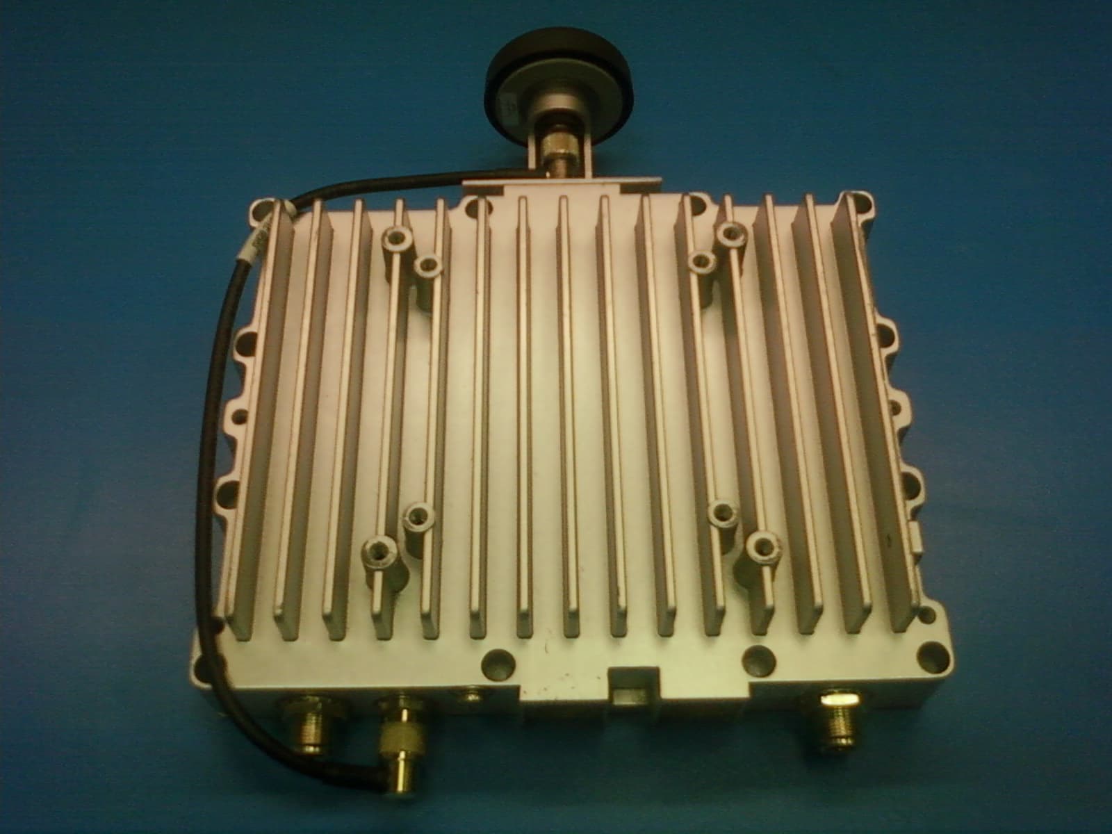
Click to zoom
Application Details
- Equipment Class
- DTS - Digital Transmission System
- Date of Grant
- May 09, 2010
- Application Purpose
- Original Equipment
- Date of Application
- May 09, 2010
- Equipment Note
- 900 MHz Broadband Base Station
- Frequency Range
- 907.25000000 - 922.70000000
- Country
- United States
Documents & Files
Document Text
Text extracted from the exhibit documents filed with the FCC. Open a document above to read the original.
Users Manual
INFRASTRUCTURE ANTENNAS Fiberglass Omnidirectional Antennas PCTEL, Inc. WEB: www.antenna.com The MFB 900/800 MHz series are base matched half wave antennas encapsu- lated in heavy duty fi berglass radomes with a thick walled aluminum mounting base for reliable long term use. All models are DC grounded and UPS ship pa ble. Features • White ultra-violet resistant pultruded fi berglass radome • Thick walled aluminum mounting base • Unity/3 dB/5 dB/7 dB models • UPS shippable • Factory tuned 800/900 MHz MAXRAD Fiberglass Base Station (MFB) Omnidirectional Antennas MMK4 MBSWM MMK9 MMK3MMK1 MFB9155 Technical Data Maximum Power: 150 watts Normal Impedance: 50 ohms Radome Material: 1.0” OD pultruded white fi berglass Radiator Material: Coated steel wire ESD Protection: DC grounded Wind Survival: 100 mph Termination: Unity and 3 dB models, N Female Mounting Base Diameter: 1-5/16” Mounting Method: Mast or wall mounted. Mounting hardware is sold separately. MMK1: light duty mast mount for antennas under 30” MMK3: light duty mast mount for antennas over 30” MMK4: heavy duty mast mount MMK9: Aluminum mast mount for 1-5/16” OD antennas MBSWM: wall mounting bracket for antennas over 30” (two are required) INFRASTRUCTURE ANTENNAS Fiberglass Base Station Omnidirectional Antennas Antenna Electrical Specifi cations ModelFrequency Range Factory Tuned Frequency Gain Bandwidth @ 1.5:1 VSWR Vertical Beamwidth @ 1/2 Power MFB8133806-866 MHz813 MHz3 dB30 MHz40° MFB8135806-866 MHz813 MHz5 dB20 MHz22° MFB8583806-866 MHz858 MHz3 dB30 MHz40° MFB8585806-866 MHz858 MHz5 dB20 MHz22° MFB8353824-896 MHz835 MHz3 dB30 MHz40° MFBW8903890-960 MHzN/A3 dB70 MHz40° MFBW8905890-960 MHzN/A5 dB70 MHz22° MFB8963896-940 MHz898 MHz3 dB30 MHz40° MFB8965(NF)896-940 MHz898 MHz5 dB20 MHz22° MFB9387896-940 MHz938 MHz7 dB20 MHz17° MFB8967(NF)896-940 MHz898 MHz7 dB20 MHz17° MFB9153902-928 MHz915 MHz 3 dB20 MHz40° MFB9155(NF)902-928 MHz915 MHz5 dB20 MHz22° MFB9155RPC902-928 MHz915 MHz5 dB20 MHz22° MFB9157(NF)*902-928 MHz915 MHz7 dB20 MHz17° Mechanical Specifi cations ModelHeightWeight (Mass) Bending Moment at Rated Wind Lateral Thrust at Rated Wind Equivalent Flat Plate Area MFB813326”1.25 lbs4.7 ft-lbs4.3 lbs.12 sq ft MFB8135*48”1.75 lbs14.2 ft-lbs8.0 lbs.22 sq ft MFB858326”1.25 lbs4.7 ft-lbs4.3 lbs.12 sq ft MFB8585*48”1.75 lbs14.2 ft-lbs8.0 lbs.22 sq ft MFB835326”1.25 lbs4.7 ft-lbs4.3 lbs.12 sq ft MFBW890323”1.25 lbs4.7 ft-lbs4.3 lbs.12 sq ft MFBW890548”1.75 lbs14.2 ft-lbs8.0 lbs.22 sq ft MFB896326”1.25 lbs4.7 ft-lbs4.3 lbs.12 sq ft MFB8965*48”1.75 lbs14.2 ft-lbs8.0 lbs.22 sq ft MFB9387*96”4.00 lbs62.5 ft-lbs15.8 lbs.44 sq ft MFB8967*96”4.00 lbs62.5 ft-lbs15.8 lbs.44 sq ft MFB915323.25”1.25 lbs4.7 ft-lbs4.3 lbs.12 sq ft MFB9155(NF)**48”1.75 lbs14.2 ft-lbs8.0 lbs.22 sq ft MFB9155RPC48”1.75 lbs14.2 ft-lbs8.0 lbs.22 sq ft MFB9157 (NF)*96”4.00 lbs62.5 ft-lbs15.8 lbs.44 sq ft PCTEL, Inc. WEB: www.antenna.com
Users Manual
Sentry4G-900 pico Base Station Operating Manual May 2010 299 Johnson Ave, Suite 110 Waseca, MN 56093 Phone: (800) 992-7774 Fax: (507) 833-6748 www.calamp.com Sentry 4G-900 pico Base Station Operating Manual Copyright © 2010 ALL RIGHTS RESERVED Dissemination or reproduction of this document, or evaluation and communication of its contents, is not authorized except where expressly permitted. Violations are liable for damages. All rights reserved, particularly for the purposes of patent application or trademark registration. This document contains proprietary information, which is protected by copyright. All rights are reserved. No part of this document may be photocopied, reproduced or translated to another language without prior written consent. Disclaimer Of Liability We have checked the contents of this manual against the hardware and software described. However, deviations from the description cannot be completely ruled out. shall not be liable for any errors or omissions contained herein or for consequential damages in connection with the furnishing, performance, or use of this material. The information given in this document is reviewed regularly and any necessary corrections will be included in subsequent editions. We appreciate any suggested improvements. We reserve the right to make technical improvements without notice. Warranty One (1) year from date of purchase, return to factory. For warranty details, contact your customer service representative. Table of Contents 1 Introduction .................................................................................................... 1 1.1 Overview .................................................................................................................................... 1 1.2 Features ..................................................................................................................................... 1 2 Getting Started................................................................................................ 2 2.1 Opening a Web Session to the Base Station ......................................................................... 2 2.2 Initial Setup the Base Station via Quick Start ........................................................................ 4 2.2.1 Verifying and Setting Operation Mode – ASN Gateway or Standalone ...................... 4 2.2.2 ASN-Gateway Mode Quick Start ................................................................................. 5 2.2.3 Standalone Mode Quick Start ...................................................................................... 6 2.3 Navigating the Web Manager Screen ...................................................................................... 8 2.3.1 Dash Board Options .................................................................................................... 9 2.3.2 Main Menu Options ...................................................................................................... 9 2.3.3 Modifying Parameters ................................................................................................ 10 2.4 Logout ...................................................................................................................................... 11 3 Backbone Configuration .............................................................................. 12 3.1 Setting the Operation Mode ................................................................................................... 12 3.2 Base Station and ASN-Gateway IP Address ........................................................................ 13 3.3 Standalone: Switching parameters ....................................................................................... 13 3.3.1 Switching Settings ..................................................................................................... 14 3.3.2 MAC Addresses Table ............................................................................................... 15 3.4 ASN-GW Mode: ASN Settings ................................................................................................ 16 3.4.1 ASN-GW Link Settings .............................................................................................. 16 3.4.2 Keep Alive Settings .................................................................................................... 17 4 Administration .............................................................................................. 18 4.1 Viewing Device Status and Information ................................................................................ 18 4.1.1 Main Status Pane ...................................................................................................... 18 4.1.2 Device Info ................................................................................................................. 19 4.2 Base Station Identification Information ................................................................................ 20 4.3 Security .................................................................................................................................... 21 4.3.1 Available Authentication Levels ................................................................................. 21 4.3.2 Defining Users and their Access Permissions ........................................................... 21 4.3.3 SNMP Settings and Trap Destination Addresses ...................................................... 22 4.4 Alarms and Traps .................................................................................................................... 23 4.4.1 Viewing a Summary of System Alarms ..................................................................... 23 4.4.2 Traps – SNMP Trap Settings ..................................................................................... 24 4.5 Software Versions Management .........................................................…
Text truncated - open the document above for the full version.
Users Manual
Sentry 4G-900 Pico Base Station Installation and Setup Guide PN: 001-9290-001 Revision 1 May 2010 II P P r r e e f f a a c c e e M M a a t t e e r r i i a a l l THE SPECIFICATIONS AND INFORMATION REGARDING THE PRODUCTS IN THIS MANUAL ARE SUBJECT TO CHANGE WITHOUT NOTICE. ALL STATEMENTS, INFORMATION, AND RECOMMENDATIONS IN THIS MANUAL ARE BELIEVED TO BE ACCURATE BUT ARE PRESENTED WITHOUT WARRANTY OF ANY KI ND, EXPRESSED OR IMPLIED. USERS MUST TAKE FULL RESPONSIBILITY FOR THEIR APPLICATION OF ANY PRODUCTS. THE SOFTWARE LICENSE AND LIMITED WARRANTY FOR THE ACCOMPANYING PRODUCT ARE SET FORTH IN THE INFORMATION PACKET SHIPPED WITH THE PRODUCT AND ARE INCORPORATED HEREIN BY THIS REFERENCE. IF YOU ARE UNABLE TO LOCATE THE SOFTWARE LICENSE OR LIMITED WARRANTY, CONTACT YOUR CALAMP REPRESENTATIVE FOR A COPY. NOTWITHSTANDING ANY OTHER WARRANTY HEREIN, ALL DOCUMENT FILES AND SOFTWARE OF THESE SUPPLIERS ARE PROVIDED “AS IS”WITH ALL FAULTS. CALAMP AND ITS SUPPLIERS DISCLAIM ALL WARRANTIES,EXPRESSED OR IMPLIED, INCLUDING,WITHOUT LIMITATION, THOSE OF MERCHANTABILITY, FITNESS FOR A PARTICULAR PURPOSE AND NONINFRINGEMENT OR ARISING FROM A COURSE OF DEALING, USAGE, OR TRADE PRACTICE. IN NO EVENT SHALL CALAMP OR ITS SUPPLIERS BE LIABLE FOR ANY INDIRECT, SPECIAL, CONSEQUENTIAL, OR INCIDENTAL DAMAGES,INCLUDING,WITHOUT LIMITATION,LOST PROFITS OR LOSS OR DAMAGE TO DATA ARISING OUT OF THE USE OR INABILITY TO USE THIS MANUAL, EVEN IF CALAMP OR ITS SUPPLIERS HAVE BEEN ADVISED OF THE POSSIBILITY OF SUCH DAMAGES. COPYRIGHT ©2010 CALAMP. ALL RIGHTS RESERVED. CALAMP AND SENTRY 4G-900™ ARE REGISTERED TRADEMARKS OF CALAMP AND/OR ITS AFFILIATES IN THE U.S.AND CERTAIN OTHER COUNTRIES. III Safety Information General Read this User Manual and follow all operating and safety instructions. The base station and antennas must be installed by a professional installer. The power requirements are indicated on the product-marking label. Do not exceed the described limits. Equipment Installation The equipment should be installed in accordance with the National Electrical Code (NEC), ANSI/NFPA 70, the Canadian Electrical Code (CEC), Part 1, CSA C22.1; and when applicable, the National Electrical Safety Code IEEE C2. And unless marked or otherwise identified, the Standard for the Protection of Electronic Computer/Data Processing Equipment, ANSI/NFPA 75. RF Exposure Sentry 4G-900 Pico Base Station is compliant with the requirements set forth in CFR 47 section 1.1307, addressing RF Exposure from radio frequency devices as defined in OET Bulletin 65. The outdoor base station should be positioned more than 0.6 feet (20 cm) from humans. Lightning Protection When Sentry 4G-900 Pico Base unit is installed in an outdoor location, all indoor components (Ethernet, power supply) should be connected through a lightning protector. The purpose of the lightning protection is to protect people and equipment located indoors from lightning that might strike the Sentry 4G-900 Pico Base unit or its outdoor cables. Therefore, the lightning protector device should be installed indoors, as close as possible to the point where the cables enter the building. The lightning protector can also be installed outdoors, as long as the cables that go from it indoors are well protected from lightning between the box and the building entrance. Power Cord Protection The Sentry 4G-900 Pico Base should always be connected to the supplied data adapter for both power supply and data transfer purposes. Any other type of connection/application of the Sentry 4G-900 Pico Base and/or supplied data adapter is not allowed. Route all power supply cords so that people cannot walk on them, or place objects on or against them. This can pinch or damage the cords. IV Servicing Do not open the cover of this product and attempt service unless instructed by a CalAmp certified technician. Refer all repairs to qualified service personnel. Removing the covers or modifying any part of this device voids its warranty. Keep away from electric power lines! Carefully read and follow all instructions in this manual. By nature of the installation, you may be exposed to hazardous environments and high voltage. Use caution when installing the outdoor system. Antenna Grounding Requirements Verify that the antenna or cable system is grounded (earthed). The antenna installation must be as per Article 810 of the NEC. Of particular note is the requirement that the grounding conductor not be less than 10 AWG (Cu). The scheme should be either in accordance with UL 96 and 96A. Lightning Protection Components and Installation Requirements for Lightning Protection Systems, or tested in accordance with UL 50 and UL 497. Outdoor Grounding System Verify that the base station is grounded. The system must be properly grounded to protect against power surges and accumulated static electricity. It is the installer responsibility to install this device in accordance with the local electrical codes. Safety Hazards Warning! Installing Sentry 4G-900 Pico Base can pose a serious hazard. Be sure to take precautions to avoid the following: Exposure to high voltage lines during installation Falling when working at heights or with ladders Injuries from dropping tools Contact with AC wiring (power system connection) Warning! To reduce the risk of fire, only use a No. 24AWG or larger telecommunication line cord between the indoor and outdoor units. V Important Note: This device complies with part 15 of the FCC Rules. Operation is subject to the following two conditions: (1) This device may not cause harmful interference, and (2) this device must accept any interference received, including interference that may cause undesired operation. Changes or modifications not expressly approved by the party responsible for compliance could void the user's authority to operate the equipment. Note: This equipment has been tested and found to comply with the limits for a Class B digital device, pursuant to part 15 of the FCC Rules. These limit…
Text truncated - open the document above for the full version.
Cover Letter(s)
A E R C E P T D A T A R A D I O L A N D C E L L O M E G A S M A R T L I N K 101-5 5 4 0 F e r r i e r S t r e e t , T M R , Q C , H 4 P 1 M 2 , C a n a d a | t 5 1 4 . 7 3 7 . 0 0 2 0 f 5 1 4 . 7 3 7 . 7 8 8 3 | w w w . c a l a m p . c o m DATE May 5 th , 2010 Equipment Authorization Division Federal Communications Commission 7435 Oakland Mills Road Columbia, MD 21046 FCC ID: EOT-1409290100 Product Name: Sentry 4G-900 pico Base Request for Confidentiality Pursuant to Sections 0.457 and 0.459 of the commissions rules, we hereby request that the following documents be held confidential: Schematics Block diagram Operational Description Parts List These materials contain trade secrets and proprietary information and are not customarily released to the public. The public disclosure of this information might be harmful to the company and provide unjustified benefits to our competitors. Dated this 5th Day of May 20 10 By: Richard Vallée, Eng Signature Printed Title: Senior Hardware Engineer On behalf of : CalAmp Wireless Newtworks Inc. Telephone: (514) 737-0020 ext 238 A E R C E P T D A T A R A D I O L A N D C E L L O M E G A S M A R T L I N K 101-5 5 4 0 F e r r i e r S t r e e t , T M R , Q C , H 4 P 1 M 2 , C a n a d a | t 5 1 4 . 7 3 7 . 0 0 2 0 f 5 1 4 . 7 3 7 . 7 8 8 3 | w w w . c a l a m p . c o m
Cover Letter(s)
A E R C E P T D A T A R A D I O L A N D C E L L O M E G A S M A R T L I N K 101-5 5 4 0 F e r r i e r S t r e e t , T M R , Q C , H 4 P 1 M 2 , C a n a d a | t 5 1 4 . 7 3 7 . 0 0 2 0 f 5 1 4 . 7 3 7 . 7 8 8 3 | w w w . c a l a m p .c o m Installation Requirements for Sentry 4G-900 Pico Base The Sentry 4G-900 pico Base from CalAmp is a radio frequency intentional radiator operating in the ISM 900 MHz band. This equipment needs to be installed by a qualified professional for multiple reasons. Some of those considerations are outlined below: In general, the installer must have a specific training relative to RF measurements, antenna gain and orientation. A good knowledge of the device user interface and commands is required. Antenna spacing determination is key to optimizing the performance of the system. The typical user will be a public safety body or industrial installation who normally require strict procedures in the installation process. Typical users of this product are public safety bodies or industrial facilities. Those users normally enforce strict procedures for the installation process. As specified in the Sentry4G-900 pico Base Installation manual, it’s the firm expectation from CalAmp that end customers, integrators and sub-contractors refer to professionals for the installation of this equipment. Dated this 5th Day of May 20 10 By: Richard Vallée, Eng Signature Printed Title: Senior Hardware Engineer On behalf of : CalAmp Wireless Networks, Inc. Telephone: (514)737-0020 ext 238
RF Exposure Info
Prediction of MPE limit at a given distance Equation from page 18 of OET Bulletin 65, Edition 97-01 where:S = power density P = power input to the antenna G = power gain of the antenna in the direction of interest relative to an isotropic radiator R = distance to the center of radiation of the antenna Maximum peak output power at device output terminal:29.97(dBm) Cable and Jumper loss1.2(dB) Maximum peak output power at antenna input terminal:28.82(dBm) Maximum peak output power at antenna input terminal:762.07901(mW) Single Antenna gain(typical):7.15(dBi) Number of Antennae2 Total Antenna gain(typical):4.139700043(dBi) Maximum antenna gain:2.594000195(numeric) Prediction distance:20(cm) Prediction frequency:907(MHz) MPE limit for uncontrolled exposure at prediction frequency:0.604666667(mW/cm²) Power density at prediction frequency:0.393278(mW/cm²) 3.932784(W/m²) Tx On time:100.000000(ms) Tx period time:100.000000(ms) Average Factor:100.000000 Average Power density at prediction frequency:3.932784(W/m²) 0.393278(mW/cm²) Maximum allowable antenna gain:6.007858834(dBi) Margin of Compliance:1.86815879 dB 2 4R PG S π =
Test Report
www.nemko.com Nemko Canada Inc., 303 River Road, R.R. 5, Ottawa, Ontario, Canada, K1V 1H2 Report number: 144079-1TRFWL Apparatus: Calamp Sentry 4G Pico Base Applicant: Calamp Corporation 101-5500 Ferrier St. Town of Mont-Royal, QC Canada H4P 1M2 FCC ID: EOT-1409290100 Test specification: Title 47 - Telecommunication Chapter I - Federal Communications Commission Subchapter A - General Part 15 - Radio Frequency Devices Subpart C - Intentional Radiators − §15.247- Operation within the bands 902–928 MHz, 2400–2483.5 MHz and 5725–5850 MHz Reviewed by: May 3, 2010 Signature Date Andrey Adelberg, Senior Wireless/EMC Specialist Tested by: Kevin Ma, Wireless/EMC Specialist Nemko Canada Inc. authorizes the applicant to reproduce this report provided it is reproduced in its entirety and for use by the company’s employees only. Any use which a third party makes of this report, or any reliance on or decisions to be made based on it, are the responsibility of such third parties. Nemko Canada Inc. accepts no responsibility for damages, if any suffered by any third party as a result of decisions made or actions based on this report. This report shall not be reproduced except in full without the written approval of the testing laboratory. Nemko Canada Inc., a testing laboratory, is accredited by the Standards Council of Canada. The tests included in this report are within the scope of this accreditation. Report Number: 144079-1TRFWL Nemko Canada Inc., 303 River Road, R.R. 5, Ottawa, Ontario, Canada, K1V 1H2 Specification: FCC 15.247 Page 2 of 40 Table of contents Section 1: Report summary.....................................................................................................................3 Section 2: Equipment under test.............................................................................................................4 2.1 Identification of equipment under test (EUT)...........................................................................4 2.2 Accessories and support equipment.......................................................................................4 2.3 EUT description.......................................................................................................................5 2.4 Technical specifications of the EUT........................................................................................5 2.5 EUT setup diagram..................................................................................................................6 2.6 Operation of the EUT during testing........................................................................................6 2.7 Modifications incorporated in the EUT.....................................................................................6 Section 3: Test conditions.......................................................................................................................7 3.1 Deviations from laboratory tests procedures...........................................................................7 3.2 Test conditions, power source and ambient temperatures......................................................7 3.3 Measurement uncertainty........................................................................................................8 3.4 Test equipment........................................................................................................................8 Section 4: Result summary......................................................................................................................9 4.1 FCC Part 15 Subpart C, 15.247: Test results..........................................................................9 Appendix A: Test results........................................................................................................................10 Clause 15.31(e) Variation of the power source...................................................................................10 Clause 15.31(m) Number of operating frequencies............................................................................11 Clause 15.203 Antenna requirement...................................................................................................12 Clause 15.207(a) Conducted limits.....................................................................................................13 Clause 15.111 Antenna power conduction limits for receivers............................................................17 Clause 15.247(a)(2) Minimum 6 dB bandwidth for digital modulation systems...................................19 Clause 15.247(b)(3) and (4) Maximum peak conducted output power for systems using digital modulation ...........................................................................................................................................22 Clause 15.247(d) Spurious emissions.................................................................................................28 Clause 15.247(e) Power spectral density............................................................................................36 Appendix B: Block diagrams of test set-ups........................................................................................40 Section 1: Report summary Report Number: 144079-1TRFWL Nemko Canada Inc., 303 River Road, R.R. 5, Ottawa, Ontario, Canada, K1V 1H2 Specification: FCC 15.247 Page 3 of 40 Section 1: Report summary This report contains an assessment of apparatus against specifications based upon tests carried out on samples submitted at Nemko Canada Inc. These tests were conducted on a sample of the equipment for the purpose of demonstrating compliance with Part 15; Subpart C. Radiated tests were conducted in accordance with ANSI C63.4-2003. Test specification: FCC Part 15 Subpart C, 15.247 Operation within the bands 902–928 MHz, 2400–2483.5 MHz and 5725–5850 MHz. Compliance status: Complies Exclusions: None Non-compliances: None Report release history: Or…
Text truncated - open the document above for the full version.
Contact Information
Applicant
Russell Cook(Director of Engineer)
[email protected]612-642-2127
Technical Contact
CALAMP WIRELESS NETWORKS INC.Andre Beaudin
[email protected]514-737-0020
101-5540 Ferrier Street · Town of Mount Royal, Quebec · Canada
Test Firm
Nemko Canada Inc. (Ottawa)Charles Neal
Technical Specifications
| # | Rule Parts | Frequency Range | Power Output |
|---|---|---|---|
| 4 | 15C | 907.25 MHz - 922.7 MHz | 993.00 mW |
Other Applications from CALAMP WIRELESS NETWORKS INC.
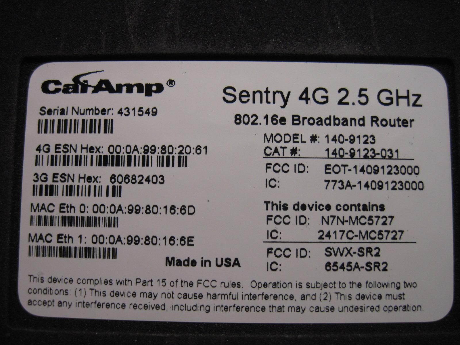
EOT-1409123000
May 15, 20112.5 GHz Wireless Broadband Route
Equipment Class
TNB - Licensed Non-Broadcast Station Transmitter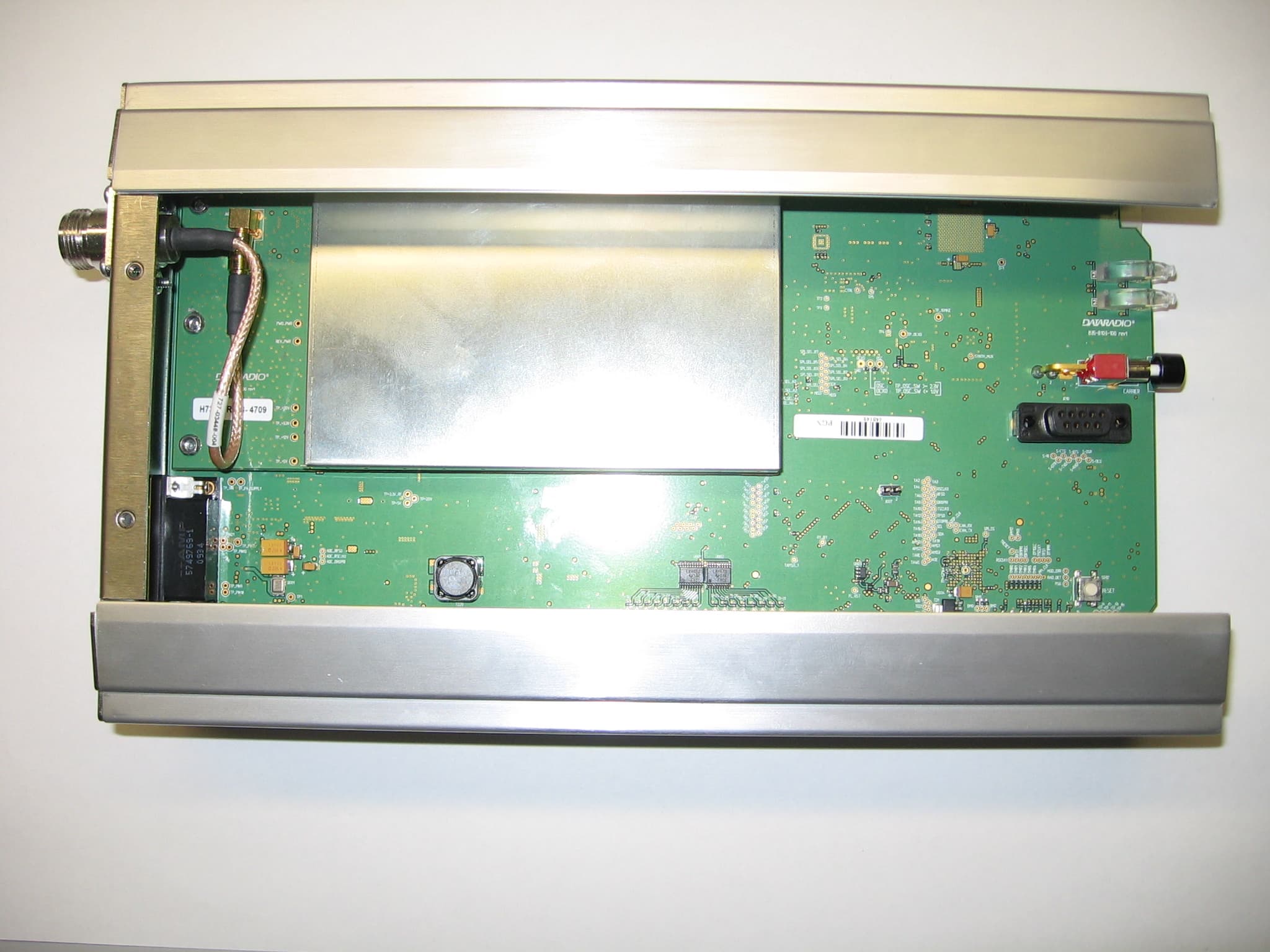
EOTBDP4-EXCT769
Sep 29, 2010700MHz Band SDR Exciter for BDP4 digital base station
Equipment Class
TNB - Licensed Non-Broadcast Station Transmitter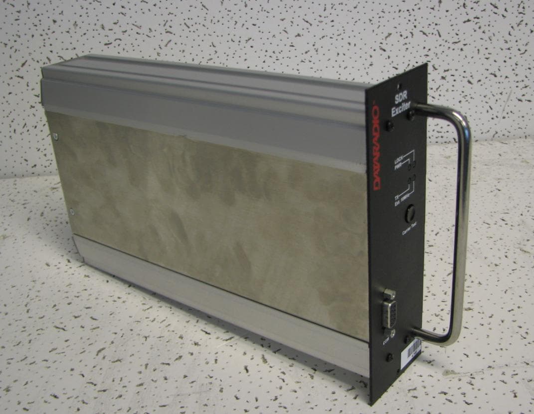
EOTBDP4-EXCT438
Jun 03, 2010UHF HIGH SDR Exciter for BDP4 digital base station
Equipment Class
TNB - Licensed Non-Broadcast Station Transmitter
EOTBDP4-EXCT403
Jun 02, 2010UHF LOW SDR Exciter for BDP4 digital base station
Equipment Class
TNB - Licensed Non-Broadcast Station Transmitter
EOT-1409193000
Feb 25, 2010Wireless router with Wi-Fi option
Equipment Class
DTS - Digital Transmission System