EP9001Security Transmitter
Timex Group USA, Inc.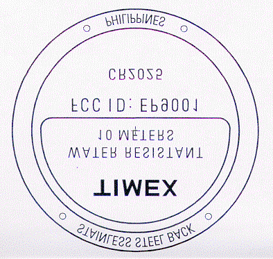
Click to zoom
Application Details
- Equipment Class
- DSC - Part 15 Security/Remote Control Transmitter
- Date of Grant
- Feb 06, 2000
- Application Purpose
- Original Equipment
- Date of Application
- Dec 19, 1999
- Equipment Note
- Security Transmitter
- Frequency Range
- 345.00000000 - 345.00000000
- Company
- Timex Group USA, Inc.
- Country
- United States
Documents & Files
Document Text
Text extracted from the exhibit documents filed with the FCC. Open a document above to read the original.
Cover Letter(s)
Confidentiality Request February 01, 2000 Timex Corporation Park Road Extension Middlebury, CT 06762-0310 FCC Application Processing Branch To: Linda Elliot and Andy Leimer Re: FCC ID EP9001 Applicant: Timex Corporation Correspondence Reference Number: EA96317 Date of Original E-mail: 01/24/2000, 01/28/2000 Sir: The schematic diagram is the item that Timex Corporation would like to keep confidential. The schematic diagram represents intellectual property specific to this application, and confidentiality minimizes exposure of the information to the general public. Best Regards, Ronald DeRosa Project Engineer [email protected]
External Photos
FCC ~ Outside Views ~ Timex Corp ~ Model M807 1 of 2 FCC ~ Outside Views ~ Timex Corp ~ Model M807 2 of 2 Line Drawing Of Case Back Above
Test Report
1 TIMEX Corporation Park Road Extension Middlebury,CT 06762-0310 Federal Communications Commission Equipment Approval Services P.O. Box 358315 Pittsburgh, PA 15251-5315 SUBJECT: Application for certification of Timex’s transmitter, model 807; FCC I.D. : EP9001 To the Federal Communications Commission: We would appreciate if you would process the Application for Certification for FCC ID: EP9001 which was submitted electronically to the FCC on December 20, 1999 for the following: Timex Corporation Park Road Extension Middlebury, CT 06762-0310 Please find enclosed a description of the transmitter circuit, schematics, label drawing, test report, photographs, under FCC Rules and Regulations, Part 15, subpart C. Please contact me if you have any questions regarding the enclosed material at (203) 573-6405, or E-mail address [email protected]. Yours Sincerely, Ronald J. DeRosa Project Engineer 2 FCC ID: EP9001 LIST OF EXHIBITS: 1) Functional Description 2) Circuit description and schematic 3) Message protocol, timing and duty cycle calculation 4) Photographs showing FCC ID label and printed circuit board 5) Report of measurements 6) Test equipment list 7) Installation instruction including FCC compliance statement and FCC user’s warning 3 EXHIBIT 1 FCC ID: EP9001 FUNCTIONAL DESCRIPTION The security watch transmitter is used in the Ademco security wireless alarm system. It is battery powered by a three volt lithium battery. The device is used in conjunction with fixed receivers and a security control system in burglary/fire alarm applications. The messages are transmitter at 345 MHz +/- 82 kHZ using on-off keyed AM modulation. 4 EXHIBIT 2 FCC ID: EP9001 CIRCUIT DESCRIPTION The watch and transmitter schematic is constructed on a single printed circuit board. The transmitter is a SAW (surface acoustic wave) resonator in a Colpitts oscillator. The transmitter is on-off keyed (AM) modulated by a control signal from the KEELOQ code hopping encoder integrated circuit manufactured by Microchip Technology Inc., which turns on or off, modulating the output signal. The RF output signal is connected to a loop antenna located under the bezel of the watch. 5 EXHIBIT 2 FCC ID: EP9001 SCHEMATIC 6 EXHIBIT 3 FCC ID: EP9001 MESSAGE PROTOCOL, TIMING AND DUTY CYCLE CALCULATION The data output is a code hopping format designed for secure keyless entry. The format combines a thirty two bit hopping code generated by a non-linear encryption algorithm, with a twenty eight bit serial number and six status bits to create a sixty six bit transmission stream. The encryption key, serial number and configuration data are stored in EEPROM which is not accessible via external connection. Ademco Security Watch Duty Cycle Calculation 100 MS duration= one packet (44.5ms) + no packet (44.5ms) + part of second packet (11.0ms) TRANSMIT TIME Total TimeX Duty Cycle =Transmit Time msec%/100msec Packet 1 PreambleXDuty Cycle=3.8X0.500=1.9 HeaderXDuty Cycle=1.7X0.000=0.0 Hopping Code WordXDuty Cycle=15.8X0.666=10.5 Fixed Code WordXDuty Cycle=16.8X0.666=11.2 StatusXDuty Cycle6.4X0.000=0.0 Off Time Off TimeXDuty Cycle=44.5X0.000=0.0 Part Of Packet 2 PreambleXDuty Cycle=3.8X0.500=1.9 HeaderXDuty Cycle=1.7X0.000=0.0 Part Of Hopping Code Word XDuty Cycle=5.5X0.666=3.7 TOTAL = 100.029.2 DUTY CYCLE Duty Cycle =Transmit Time / Total Time = 29.2% 7 EXHIBIT 4 FCC ID: EP9001 PHOTOGRAPHS SHOWING FCC ID LABEL 8 EXHIBIT 4 FCC ID: EP9001 PHOTOGRAPHS OF THE PRINTED CIRCUIT BOARD 9 EXHIBIT 4 FCC ID: EP9001 10 EXHIBIT 5 FCC ID: EP9001 REPORT OF MEASUREMENT Measurements were made in accordance with the procedures and reporting on ANSI C63.4-1992. The test set-up (C63.4 section 10.0.3) is shown in the attached drawing. The sequence of testing (C63.4 section 10.1.7) for radiated emissions is as follows: A preliminary scan was conducted with the receiver antenna close to the EUT in order to identify the emission characteristics of the EUT (C63.4 section 8.3.1.1). The antenna and EUT were then placed at the proper separation with the EUT positioned on a non- conducting turntable. The EUT was rotated on the turntable to maximize the received signal strength, and then the receiver antenna height was varied to further maximize the received reading. Thereafter, the device was again rotated to a peak output position and the antenna height was re-adjusted for maximum received signal. This procedure was re- iterated until there was no further increase in signal level. This procedure was performed with the EUT rotating in three orthogonal planes (C63.4 section 13.1.4.4) to generate a final maximum reading which is recorded on the radiated emissions result sheet. See Exhibit 6 for the list of test equipment (C63.4 section 10.1.4). Note: Spectrum Analyzer resolution bandwidths set as follows (video bandwidth set greater than RBW): For occupied bandwidth measurement, RBW = 100 kHz, in accordance with the minimum RBW allowed by C63.4, which requires RBW greater than 5% of the FCC required occupied bandwidth specification of 0.25% of center frequency. For radiated emissions below 1 GHz, the RBW = 100 kHz, with detector function set to peak. For radiated emissions above 1 GHz, the RBW = 1 MHz, with the detector function set to peak. Occupied bandwidth is shown on the attached plot. Radiated bandwidth are recorded on the attached sheet. 11 EXHIBIT 5 FCC ID: EP9001 12 EXHIBIT 5 FCC ID: EP9001 13 EXHIBIT 5 FCC ID: EP9001 14 EXHIBIT 6 FCC ID: EP9001 TEST EQUIPMENT LIST MODELDESCRIPTIONCALIBRATEDS/N AntennaRoberts dipole 30-65 MHz1/20/99110 AntennaRoberts dipole 65-180 MHz1/20/99110 AntennaRoberts dipole 180-400 MHz1/20/99110 AntennaRoberts dipole 400-1000 MHz1/20/99110 AntennaRoberts dipole 1-18 GHz1/20/996127 Cable RG 58U 2784Tektronix Spectrum Analyzer7/29/98B010165 15 EXHIBIT 7 FCC ID: EP9001 FCC COMPIANCE STATEMENT AND FCC USER’S WARNING FROM THE INSTALLATION INSTRUCTIONS
Test Report
1 TIMEX Corporation Park Road Extension Middlebury,CT 06762-0310 Federal Communications Commission Equipment Approval Services P.O. Box 358315 Pittsburgh, PA 15251-5315 SUBJECT: Application for certification of Timex’s transmitter, model 807; FCC I.D. : EP9001 To the Federal Communications Commission: We would appreciate if you would process the Application for Certification for FCC ID: EP9001 which was submitted electronically to the FCC on December 20, 1999 for the following: Timex Corporation Park Road Extension Middlebury, CT 06762-0310 Please find enclosed a description of the transmitter circuit, schematics, label drawing, test report, photographs, under FCC Rules and Regulations, Part 15, subpart C. Please contact me if you have any questions regarding the enclosed material at (203) 573-6405, or E-mail address [email protected]. Yours Sincerely, Ronald J. DeRosa Project Engineer 2 FCC ID: EP9001 LIST OF EXHIBITS: 1) Functional Description 2) Circuit description and schematic 3) Message protocol, timing and duty cycle calculation 4) Photographs showing FCC ID label and printed circuit board 5) Report of measurements 6) Test equipment list 7) Installation instruction including FCC compliance statement and FCC user’s warning 3 EXHIBIT 1 FCC ID: EP9001 FUNCTIONAL DESCRIPTION The security watch transmitter is used in the Ademco security wireless alarm system. It is battery powered by a three volt lithium battery. The device is used in conjunction with fixed receivers and a security control system in burglary/fire alarm applications. The messages are transmitter at 345 MHz +/- 82 kHZ using on-off keyed AM modulation. 4 EXHIBIT 2 FCC ID: EP9001 CIRCUIT DESCRIPTION The watch and transmitter schematic is constructed on a single printed circuit board. The transmitter is a SAW (surface acoustic wave) resonator in a Colpitts oscillator. The transmitter is on-off keyed (AM) modulated by a control signal from the KEELOQ code hopping encoder integrated circuit manufactured by Microchip Technology Inc., which turns on or off, modulating the output signal. The RF output signal is connected to a loop antenna located under the bezel of the watch. 5 EXHIBIT 2 FCC ID: EP9001 SCHEMATIC 6 EXHIBIT 3 FCC ID: EP9001 MESSAGE PROTOCOL, TIMING AND DUTY CYCLE CALCULATION The data output is a code hopping format designed for secure keyless entry. The format combines a thirty two bit hopping code generated by a non-linear encryption algorithm, with a twenty eight bit serial number and six status bits to create a sixty six bit transmission stream. The encryption key, serial number and configuration data are stored in EEPROM which is not accessible via external connection. Ademco Security Watch Duty Cycle Calculation 100 MS duration= one packet (44.5ms) + no packet (44.5ms) + part of second packet (11.0ms) TRANSMIT TIME Total TimeX Duty Cycle =Transmit Time msec%/100msec Packet 1 PreambleXDuty Cycle=3.8X0.500=1.9 HeaderXDuty Cycle=1.7X0.000=0.0 Hopping Code WordXDuty Cycle=15.8X0.666=10.5 Fixed Code WordXDuty Cycle=16.8X0.666=11.2 StatusXDuty Cycle6.4X0.000=0.0 Off Time Off TimeXDuty Cycle=44.5X0.000=0.0 Part Of Packet 2 PreambleXDuty Cycle=3.8X0.500=1.9 HeaderXDuty Cycle=1.7X0.000=0.0 Part Of Hopping Code Word XDuty Cycle=5.5X0.666=3.7 TOTAL = 100.029.2 DUTY CYCLE Duty Cycle =Transmit Time / Total Time = 29.2% 7 EXHIBIT 4 FCC ID: EP9001 PHOTOGRAPHS SHOWING FCC ID LABEL 8 EXHIBIT 4 FCC ID: EP9001 PHOTOGRAPHS OF THE PRINTED CIRCUIT BOARD 9 EXHIBIT 4 FCC ID: EP9001 10 EXHIBIT 5 FCC ID: EP9001 REPORT OF MEASUREMENT Measurements were made in accordance with the procedures and reporting on ANSI C63.4-1992. The test set-up (C63.4 section 10.0.3) is shown in the attached drawing. The sequence of testing (C63.4 section 10.1.7) for radiated emissions is as follows: A preliminary scan was conducted with the receiver antenna close to the EUT in order to identify the emission characteristics of the EUT (C63.4 section 8.3.1.1). The antenna and EUT were then placed at the proper separation with the EUT positioned on a non- conducting turntable. The EUT was rotated on the turntable to maximize the received signal strength, and then the receiver antenna height was varied to further maximize the received reading. Thereafter, the device was again rotated to a peak output position and the antenna height was re-adjusted for maximum received signal. This procedure was re- iterated until there was no further increase in signal level. This procedure was performed with the EUT rotating in three orthogonal planes (C63.4 section 13.1.4.4) to generate a final maximum reading which is recorded on the radiated emissions result sheet. See Exhibit 6 for the list of test equipment (C63.4 section 10.1.4). Note: Spectrum Analyzer resolution bandwidths set as follows (video bandwidth set greater than RBW): For occupied bandwidth measurement, RBW = 100 kHz, in accordance with the minimum RBW allowed by C63.4, which requires RBW greater than 5% of the FCC required occupied bandwidth specification of 0.25% of center frequency. For radiated emissions below 1 GHz, the RBW = 100 kHz, with detector function set to peak. For radiated emissions above 1 GHz, the RBW = 1 MHz, with the detector function set to peak. Occupied bandwidth is shown on the attached plot. Radiated bandwidth are recorded on the attached sheet. 11 EXHIBIT 5 FCC ID: EP9001 12 EXHIBIT 5 FCC ID: EP9001 13 EXHIBIT 5 FCC ID: EP9001 14 EXHIBIT 6 FCC ID: EP9001 TEST EQUIPMENT LIST MODELDESCRIPTIONCALIBRATEDS/N AntennaRoberts dipole 30-65 MHz1/20/99110 AntennaRoberts dipole 65-180 MHz1/20/99110 AntennaRoberts dipole 180-400 MHz1/20/99110 AntennaRoberts dipole 400-1000 MHz1/20/99110 AntennaRoberts dipole 1-18 GHz1/20/996127 Cable RG 58U 2784Tektronix Spectrum Analyzer7/29/98B010165 15 EXHIBIT 7 FCC ID: EP9001 FCC COMPIANCE STATEMENT AND FCC USER’S WARNING FROM THE INSTALLATION INSTRUCTIONS
Contact Information
Applicant
Sam Everett(Quality Regulatory Engineer)
Technical Contact
Timex CorporationRonald J DeRosa
(203) 573-6405
Park Road Extension · Middlebury
Non-Technical Contact
Timex CorporationRonald J DeRosa
[email protected](203) 573-6405
Test Firm
AdemcoKenneth Addy
Technical Specifications
| # | Rule Parts | Frequency Range | Power Output | Tolerance |
|---|---|---|---|---|
| 1 | 15C | 345 MHz - 345 MHz | - | % |
Other Applications from Timex Group USA, Inc.

EP9-TMXM05L
Jan 30, 2020modular
Equipment Class
DXX - Part 15 Low Power Communication Device Transmitter
EP9-TMXM05J
Jan 30, 2020modular
Equipment Class
DXX - Part 15 Low Power Communication Device Transmitter
EP9-TMXM372
Sep 18, 2015Timex Metropolitan+
Equipment Class
DTS - Digital Transmission System
EP9-TMXM053
Feb 18, 2015M053 - Ironman Classic 50 Move+
Equipment Class
DSS - Part 15 Spread Spectrum Transmitter
EP9-TMXM049
Feb 18, 2015M049 - Ironman Classic 50 Move+
Equipment Class
DSS - Part 15 Spread Spectrum Transmitter