EP9TMXHRMheart rate monitor
Timex Group USA, Inc.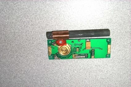
Click to zoom
Application Details
- Equipment Class
- DCD - Part 15 Low Power Transmitter Below 1705 kHz
- Date of Grant
- Jul 18, 1999
- Application Purpose
- Original Equipment
- Date of Application
- May 04, 1999
- Equipment Note
- heart rate monitor
- Frequency Range
- 0.12900000 - 0.14100000
- Company
- Timex Group USA, Inc.
- Country
- United States
Documents & Files
Document Text
Text extracted from the exhibit documents filed with the FCC. Open a document above to read the original.
Test Report
Intertek Testing Services NA Inc. 70 Codman Hill Road Boxborough, MA 01719 Telephone (978) 263-2662 Fax (978) 263-7086 Timex Communications, Inc. Emissions Testing Performed on the Heart Rate Monitor Systems Model(s): M821 HRM FCC Part 15, Subpart C, Section '15.209 Date of Test: March 31, 1999 JOB #99007699B KPS/Rbt April 2, 1999 DOT: March 31, 1999 Contact: Mr. Ron DeRosa Total No. of Pages Contained in this Report: All services undertaken are subject to the following general policy: Reports are submitted for exclusive use of the client to whom they are addressed. Their significance is subject to the adequacy and representative character of the samples and to the comprehensiveness of the tests, examinations or surveys made. No quotations from reports or use of Intertek Testing Services NA Inc. name is permitted except as expressly authorized by Intertek Testing Services NA Inc. in writing. Although the test procedures and reporting done are NVLAP approved, NVLAP does not endorse labs or their data. INTERTEK TESTING SERVICES NA INC. TO:Timex Communications, Inc. Mr. Ron DeRosa FROM:Kouma P. Sinn DATE:March 31, 1999 JOB #:J99007699B RE:Emissions Testing Performed On The Heart Rate Monitor Systems, Model(s) M821 HRM On March 31, 1999, we tested the Heart Monitor Systems, Model(s): M821 HRM to determine if it was in compliance with the FCC Part 15 requirements, Subpart C, Section '15.209. A production version of the sample was received on March 31, 1999 in good condition. We found that the unit met the Part 15, Subpart C, Section '15.209 when tested as received. Fundamental output power is regulated under FCC Part 15 Subpart C, Section '15.209. Harmonic emissions which lie in the forbidden bands of '15.205 are required to meet the General Radiated Emission Limits of '15.209. The maximum level of the fundamental signal at 0.1412 MHZ was 1.1 μV/m which is 23.76 dB below the FCC limit. The worst-case harmonic emission was 43.69 dB below the FCC limit (see Tables 1 and 2). No line-conducted emissions measurements were performed as the unit is battery powered. In summary, this report confirms that the Heart Rate Monitor Systems, Model(s): M821 HRM, is compliant with the FCC Part 15, Subpart C, Section '15.209 requirements when production units conform with the initial sample. Please address all questions and comments concerning this report to Andrew J. Bellezza, Staff Engineer/Emissions. INTERTEK TESTING SERVICES Laboratory Measurements, Intentional RadiatorsJob Number: J99007699B Rev. September 1, 1992 (PT15C.IR) The following is a description of the test procedure used by Intertek Testing Services in the measurements of transmitters operating under Part 15, Subpart C, General Requirements. A.Test Set-Up: The test set-up and procedures described below are designed to meet the requirements of ANSI C63.4 (1992). 1.The test site is a wooden structure with a groundplane. The site has attenuation characteristics which meet the requirements of ANSI C63.4 (1992). Information on the site has been filed with the FCC as required by Rule '2.948. The address of the site is 70 Codman Hill Road, Boxborough, Massachusetts. 2.Power to the site is nominal line voltage of 117 V AC and 230 V AC , 60 Hz. 3.The equipment under test (EUT) is placed on a wooden turntable which is four feet in diameter and approximately one meter in height above the groundplane. During the radiated emissions test, the turntable is rotated and any cables leaving the EUT are manipulated to find the configuration resulting in maximum emissions. The antenna height and polarization are also varied during the search for maximum signal levels. The height of the antenna is varied from one meter to four meters. 4.Detector function for radiated emissions is in peal or quasi-peak mode. Average readings, when required, are taken by measuring the duty cycle of the equipment under test and subtracting the corresponding amount in dB from the measured peak readings according to the following formula: Averaging Factor in dB = 20 LOG (duty cycle) INTERTEK TESTING SERVICES Laboratory Measurements, Intentional RadiatorsJob Number: J99007699B Rev. September 1, 1992 (PT15C.IR) A.Test Set Up (cont'd) The time period over which the duty cycle is measured is 100 msec. The worst-case (highest percentage on) duty cycle is used and described specifically in the data section. The duty cycle is measured by placing the spectrum analyzer in zero scan (receiver mode) and linear mode at maximum bandwidth (3 MHZ at 3 dB down) and viewing the resulting time domain signal output from the analyzer on a Tektronix 465 Oscilloscope. The oscilloscope is used because of its superior time base and triggering facilities. A drawing or photograph of the worst-case duty cycle as detected in this manner is included as an attached page. 5.Antennas used below 1000 MHZ were EMCO Biconolog Antenna. For measurements between 1000 MHZ and 18000 MHZ, where required, an Emco Double-Ridge Guide Horn Antenna was used. Alternately, for measurements above 1 GHz, an EMCO M/N 3115 Horn Antenna may have been used. 6.The field strength measuring equipment used included: Spectrum Analyzer:Hewlett Packard 8593A Preamplifier:CDI P-950 LISN:Solar Electronics Additional equipment or comments: Equipment is calibrated at frequent intervals. INTERTEK TESTING SERVICES Laboratory Measurements, Intentional RadiatorsJob Number: J99007699B Rev. September 1, 1992 (PT15C.IR) A.Test Set Up (cont'd) 7.The frequency range to be scanned is from the lowest radio frequency signal generated in the device which is greater than 9 kHz to the tenth harmonic of the highest fundamental frequency, or 40 GHz, whichever is lower. For line-conducted emissions, the range scanned is 450 kHz to 30 MHZ. 8.The EUT is warmed up for 15 minutes prior to the test. AC power to the unit is varied from 85% to 115% nominal and variation in the fundamental emission field strength is recorded. If battery powered, a new battery is used. 9.Conduc…
Text truncated - open the document above for the full version.
Contact Information
Applicant
Sam Everett(Quality Regulatory Engineer)
Technical Contact
Intertek Testing Services NA Inc.Andrew J Bellezza
[email protected]978-635-8641
70 Codman Hill Road · Boxborough, Massachusetts · United States
Non-Technical Contact
Intertek Testing Services NA Inc.Jody K Zarnowiec
[email protected]978-635-8693
Technical Specifications
| # | Rule Parts | Frequency Range | Power Output |
|---|---|---|---|
| 1 | 15C | 0.129 MHz - 0.141 MHz | - |
Other Applications from Timex Group USA, Inc.

EP9-TMXM05L
Jan 30, 2020modular
Equipment Class
DXX - Part 15 Low Power Communication Device Transmitter
EP9-TMXM05J
Jan 30, 2020modular
Equipment Class
DXX - Part 15 Low Power Communication Device Transmitter
EP9-TMXM372
Sep 18, 2015Timex Metropolitan+
Equipment Class
DTS - Digital Transmission System
EP9-TMXM053
Feb 18, 2015M053 - Ironman Classic 50 Move+
Equipment Class
DSS - Part 15 Spread Spectrum Transmitter
EP9-TMXM049
Feb 18, 2015M049 - Ironman Classic 50 Move+
Equipment Class
DSS - Part 15 Spread Spectrum Transmitter