EP9TMXM185Low power transmitter
Timex Group USA, Inc.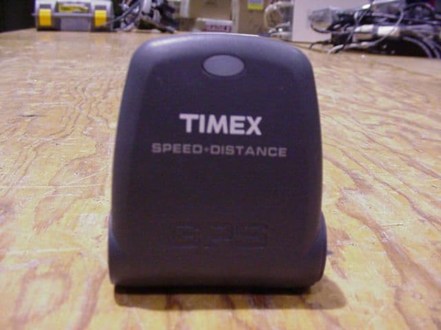
Click to zoom
Application Details
- Equipment Class
- DXX - Part 15 Low Power Communication Device Transmitter
- Date of Grant
- Jun 20, 2004
- Application Purpose
- Original Equipment
- Date of Application
- Jun 20, 2004
- Equipment Note
- Low power transmitter
- Frequency Range
- 0.13750000 - 0.14100000
- Company
- Timex Group USA, Inc.
- Country
- United States
Documents & Files
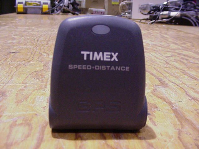
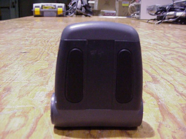
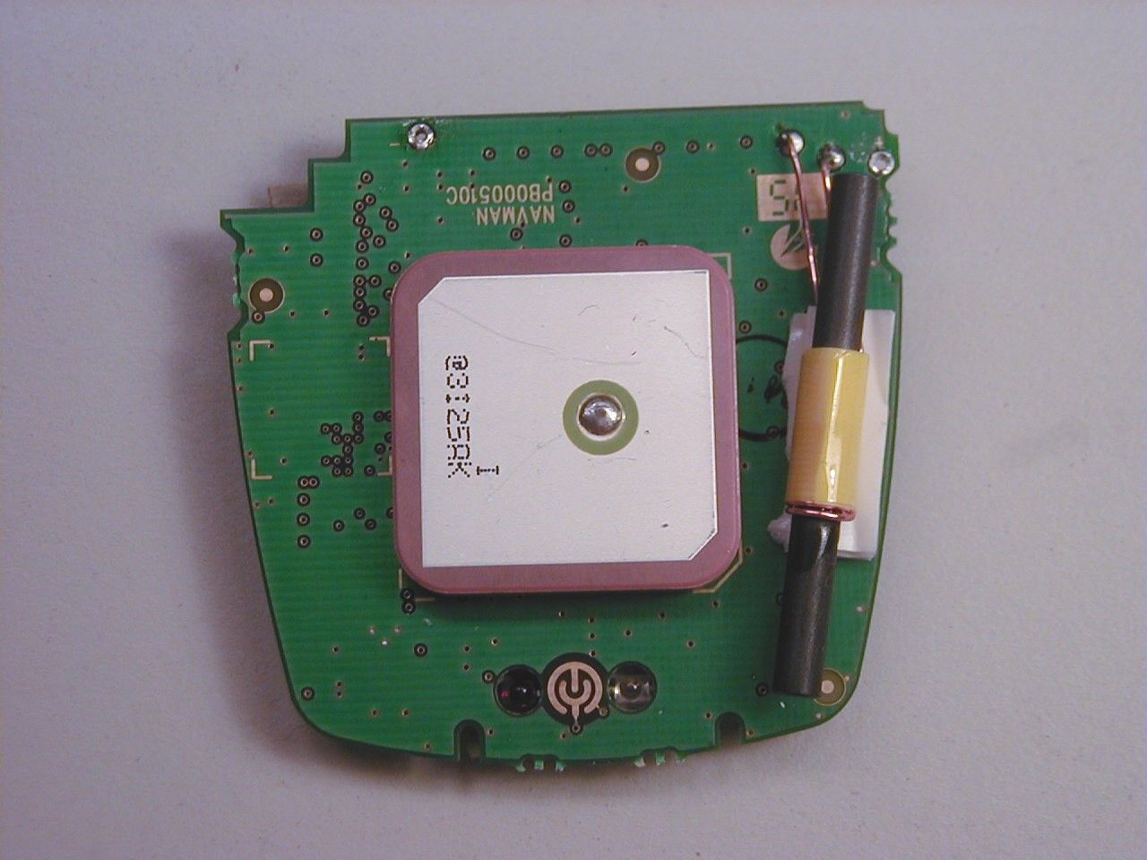
Document Text
Text extracted from the exhibit documents filed with the FCC. Open a document above to read the original.
Users Manual
TIMEX is a registered trademark of Timex Corporation. ©2003 Timex Corporation. W-184 185-095000 English page 1 Français page 21 Español página 39 576_BOOKLET.qxd 5/6/04 3:07 PM Page 1 1 Heart Rate Sensor Speed + Distance Sensor W atches are for more than keeping time. Digital technology gives your watch the ability to display your heart rate or measure yourspeed and distance traveled. These functions require the use ofexternal modules that transmit information wirelessly to yourwatch. This booklet provides instructions for properly setting up,operating and maintaining these devices. Look for the section thatis appropriate for the type of device you have.F or information on using your watch, consult the watch instruction booklet. Timex ® Fitness Sensors 576_BOOKLET.qxd 5/6/04 3:07 PM Page 1 3 W arning This is not a medical device and is not recommended for useby persons with serious heart conditions. You should alwaysconsult your physician before beginning or modifying anexercise program.Interference with the radio signal, poor contact between your skinand the chest strap, and other factors may prevent accurate transmission of heart rate data.MaintenanceRinse Heart Rate Sensor and strap in fresh water to avoid build up ofmaterials that can interfere with the measurement of your heart rate.T ransmitter Battery Life and Replacement Battery life of the transmitter should exceed two years, basedupon using it an hour a day. Greater usage will shorten the batterylife. Replace transmitter battery when any of the following occur:• The watch no longer receives heart rate information from the chest transmitter when properly worn on the chest. • Error messages (COMM ERR, SIGNAL LOST) appear with increasedfrequency on the display. Battery ReplacementNOTE: You’ll need to have a device (such as a watch) capableof displaying heart rate information to verify that the new Heart Rate MonitorHow the Digital Heart Rate Monitor WorksThe Heart Rate Monitor is a combination of a Heart Rate Sensor and a sport watch. The Heart Rate Sensor attaches to your chest and measures the electrical signals generated by the heart as it isbeating. Using this information, it then calculates your heart rateand transmits it to your watch. You simply glance at the watch during exercise/training to make sure you are in the appropriateheart rate range to maintain or improve your fitness level.How to Use the Digital Heart Rate Monitor1. Wet the Heart Rate Sensor pads. THIS IS ESSENTIAL for proper operation of the Heart Rate Monitor. 2. Put on the chest strap. Fasten the strap snugly around your chest, just below the breasts. Be sure the transmitter iscentered on the chest and is right sideup so the logo can be read by someonefacing you. 3. Start the Heart Rate Monitor: Refer to the user manual for your watch for detailedinstructions on viewing heart rate data. 2 Sensor Pads 576_BOOKLET.qxd 5/6/04 3:07 PM Page 2 5 battery has been inserted correctly. Use a coin to open thebattery compartment cover (back of transmitter).• Insert new battery (CR2032 or equivalent) with “ + ”facing you. • Push the reset button next to the battery. Use a toothpick or straightened paper clip. • Reinstall battery cover.• Perform quick test of the unit: 1. Move away from sources of electrical or radio interference.2. Liberally moisten the Heart Rate Sensor pads and put the chest strap around your chest, securely against your skin. 3. Activate the heart rate monitor function on the watch.4. Within a few seconds, the heart symbol on the watch display should begin flashing, indicating that the transmitter is active.This confirms that the battery was installed correctly.NOTE: A heart rate value does not need to appear on the display during this test. IF FLASHING HEART DOES NOT APPEAR ON WATCH:• Press the reset switch in the battery compartment again and replace the battery cover. • Reinstall the battery, and repeat test procedure above. W ater Resistance The Heart Rate Sensor withstands water pressure to 60 p.s.i. Seechart at end of booklet for equivalents. WA RNING: The Heart Rate Sensor will not display heart rate when operated under water. 4 Speed + Distance SensorHow the Speed and Distance System WorksThe Speed + Distance (S+D) Sensor acquires signals from orbitingGPS (Global Positioning System) satellites to determine your positionand changes in position anywhere on the globe. This informationis transmitted wirelessly to your watch so that it can computeyour speed, pace and distance traveled. For additional informationon determining your speed and distance, see the instructions foryour watch.About GPS Lock Times• On first use, the S+D Sensor can take up to 5 minutes or even longer to establish a link with the satellites. After that, the unittypically needs only one minute. • If you move hundreds of miles from the location where you last used the S+D Sensor or if you leave the S+D Sensor powered upindoors for long periods of time before going outdoors, the searchmay take longer than expected. • For shortest GPS lock times, try to minimize movement while the indicator light is flashing red. 576_BOOKLET.qxd 5/6/04 3:07 PM Page 4 7 Operating the S+D SensorF or best results, the Sensor needs a clear view of the sky. • Press and hold the S+D SENSOR ON/OFF button to turn on the receiver. You should be outdoors in an open area. If the buttonlight glows red immediately (continuously, not flashing), the bat-tery is exhausted to the point where GPS operation is not possi-ble and the battery must be replaced. The ON/OFF button on the S+D Sensor will initially flash red while the S+D Sensor cal-culates its position relative to the GPS satellites. The text“SEARCHING” may appear on the watch display if using a com-patible Timex® watch. • The ON/OFF button will flash green when the S+D Sensor has successfully acquired signals from the satellites. Speed and distance information is now being transmitted to the watch (orother device). • To turn off the S+D Sensor, press and…
Text truncated - open the document above for the full version.
ID Label/Location Info
Title: Latimer Part Number Label Document No: Revision: Page No: 1 of 1 2002 © Navman NZ Limited OEM Solutions NAVMAN is a registered trademark of Navman NZ Limited. All rights reserved. LABEL - Latimer Project AA004210 Material Print Size Quantity Other Requirements Approved White polyester gloss Fasson S333. Black print on matt laminate 27 x 40mm Adhesive backing. Water resistant materials. D. Marais This document was created with Win2PDF available at http://www.daneprairie.com. The unregistered version of Win2PDF is for evaluation or non-commercial use only.
Test Report
Underwriters Laboratories Inc. A not-for-profit organization dedicated 1285 Walt Whitman Rd. To public safety and committed to Melville, NY 11747 Quality service for over 100 years Tel: (631) 271-6200 Fax: (631) 439-6095 Project: 04ME06985 File: NC4557 Date: 5/18/04 Model: M185 FCC ID: EP9TMXM185 Test Report On Electromagnetic Compatibility Testing Copyright 2003 Underwriters Laboratories Inc. Underwriters Laboratories Inc. authorizes the above-named company to reproduce this Report provided it is reproduced in its entirety. File NumBer: NC4557 Issued: 6/1/04 Project Number: 04ME06985 Model Number: M185 FCC ID: EP9TMXM185 ____________________________________________________________________________________________________ ____________________________________________________________________________________________________ Page 2 of 34 Underwriters Laboratories Inc. 1285 Walt Whitman Rd. Melville, New York 11747 USA Tel.: 631 271-6200 Fax: 631 439-6095 Rev. No 1.0 Test Report Details Tests Performed By: Underwriters Laboratories Inc. 1285 Walt Whitman Rd. Melville, NY 11747 Tests Performed For: Timex Corporation 555 Christian Road Middlebury, CT 06762 Applicant Contact: John D. Davino Title: Software Test Engineer Phone: 203- 346-4340 Fax: 203-346-7146 E-mail: [email protected] Test Report Date: 5/18/2004 Product Type: GPS Transceiver Model Number: M185 Sample Serial Number: #4 Sample Tag Number: 0578185001 Sample Receive Date: 5/10/04 EUT Category: ITE Testing Start Date: 5/12/04 Date Testing Complete: 5/13/2004 Underwriters Laboratories Inc. reports apply only to the specific samples tested under stated test conditions. All samples tested were in good operating condition throughout the entire test program. It is the manufacturer's responsibility to assure that additional production units of this model are manufactured with identical electrical and mechanical components. Underwriters Laboratories Inc. shall have no liability for any deductions, inferences or generalizations drawn by the client or others from Underwriters Laboratories Inc. issued reports. This report shall not be used to claim, constitute or imply product certification, approval, or endorsement by NVLAP, A2LA, or any agency of the US government. This report may contain test results that are not covered by the NVLAP or A2LA accreditation. The scope of accreditation is limited to the specific tests that are listed on the NVLAP and/or A2LA certificates provided at the end of this report. File NumBer: NC4557 Issued: 6/1/04 Project Number: 04ME06985 Model Number: M185 FCC ID: EP9TMXM185 ____________________________________________________________________________________________________ ____________________________________________________________________________________________________ Page 3 of 34 Underwriters Laboratories Inc. 1285 Walt Whitman Rd. Melville, New York 11747 USA Tel.: 631 271-6200 Fax: 631 439-6095 Rev. No 1.0 Report Directory 1.0 G E N E R A L - Product Description..........................................................................................4 1.1 Device Configuration During Test......................................................................................................5 1.1.1 Equipment Used During Test:....................................................................................5 1.1.2 Input/Output Ports:................................................................................................5 1.1.3 EUT Internal Operating Frequencies:...........................................................................5 1.1.4 Power Interface:....................................................................................................6 1.2 EUT Operation Modes:......................................................................................................................6 1.3 EUT Configuration Modes:................................................................................................................6 1.4 Block Diagram:.................................................................................................................................7 1.5 Deviations from standard test methods................................................................................................7 1.6 Device Modifications Necessary for Compliance.................................................................................8 1.7 Test Summary...................................................................................................................................8 2.0 Conclusion:...................................................................................................................................9 3.0 FCC Labeling Information........................................................................................................10 3.1 Compliance information..................................................................................................................10 3.2 Labeling.........................................................................................................................................11 3.3 User information.............................................................................................................................13 4.0 Calibration of Equipment Used for Measurement....................................................................13 5.0 EMISSIONS TEST REGULATIONS........................................................................................14 5.1.1 Radiated Emissions Test (10 Meter Semi-Anechoic Chamber)............................................15 5.1.2 Sample Calculations..............................................................................................28 Appendix A...............................................................................................................................................33 Accreditations and Authorizations..............................................…
Text truncated - open the document above for the full version.
Test Setup Photos
R R a a d d i i a a t t e e d d E E m m i i s s s s i i o o n n s s F F r r o o n n t t – – 3 3 0 0 - - 1 1 0 0 0 0 0 0 M M H H z z R R a a d d i i a a t t e e d d E E m m i i s s s s i i o o n n s s R R e e a a r r – – 3 3 0 0 - - 1 1 0 0 0 0 0 0 M M H H z z R R a a d d i i a a t t e e d d E E m m i i s s s s i i o o n n s s F F r r o o n n t t – – 9 9 k k H H z z - - 3 3 0 0 M M H H z z R R a a d d i i a a t t e e d d E E m m i i s s s s i i o o n n s s R R e e a a r r – – 9 9 k k H H z z - - 3 3 0 0 M M H H z z R R a a d d i i a a t t e e d d E E m m i i s s s s i i o o n n s s F F r r o o n n t t – – 1 1 - - 1 1 0 0 G G H H z z R R a a d d i i a a t t e e d d E E m m i i s s s s i i o o n n s s R R e e a a r r – – 1 1 - - 1 1 0 0 G G H H z z
Contact Information
Applicant
Sam Everett(Quality Regulatory Engineer)
Technical Contact
Timex CorporationJohn Davino
[email protected]203-346-4340
555 Christian Road · Middlebury, Connecticut · United States
Non-Technical Contact
Timex CorporationBrian J Hudson
[email protected]203-346-5321
Test Firm
Underwriters Laboratories, Inc.Rick Titus
Technical Specifications
| # | Rule Parts | Frequency Range | Power Output |
|---|---|---|---|
| 1 | 15C | 0.1375 MHz - 0.141 MHz | - |
Other Applications from Timex Group USA, Inc.

EP9-TMXM05L
Jan 30, 2020modular
Equipment Class
DXX - Part 15 Low Power Communication Device Transmitter
EP9-TMXM05J
Jan 30, 2020modular
Equipment Class
DXX - Part 15 Low Power Communication Device Transmitter
EP9-TMXM372
Sep 18, 2015Timex Metropolitan+
Equipment Class
DTS - Digital Transmission System
EP9-TMXM053
Feb 18, 2015M053 - Ironman Classic 50 Move+
Equipment Class
DSS - Part 15 Spread Spectrum Transmitter
EP9-TMXM049
Feb 18, 2015M049 - Ironman Classic 50 Move+
Equipment Class
DSS - Part 15 Spread Spectrum Transmitter