EP9TMXM515Heart Rate Monitor
Timex Group USA, Inc.
Click to zoom
Application Details
- Equipment Class
- DCD - Part 15 Low Power Transmitter Below 1705 kHz
- Date of Grant
- Sep 10, 2002
- Application Purpose
- Original Equipment
- Date of Application
- Sep 10, 2002
- Equipment Note
- Heart Rate Monitor
- Frequency Range
- 0.13750000 - 0.14103000
- Company
- Timex Group USA, Inc.
- Country
- United States
Documents & Files
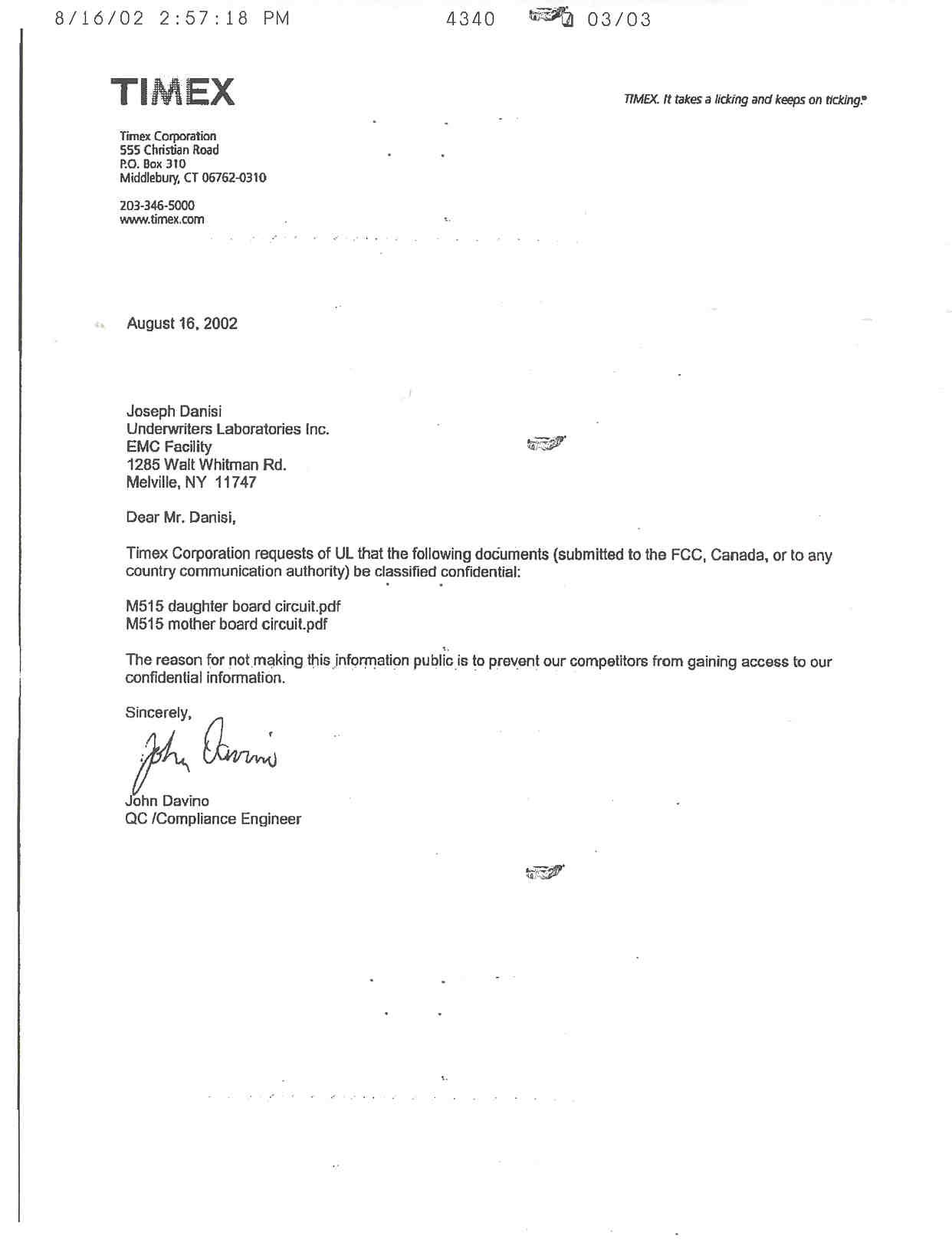
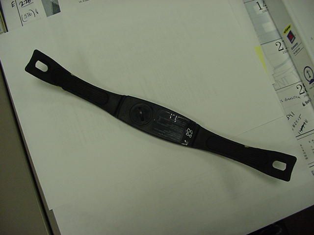
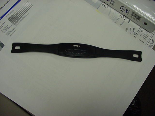
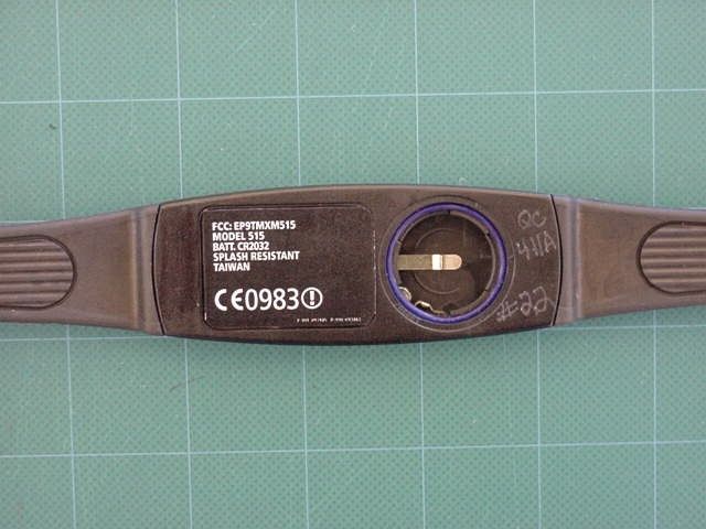
Document Text
Text extracted from the exhibit documents filed with the FCC. Open a document above to read the original.
Users Manual
1 THE TIMEX DIGITAL HEART RATE MONITOR AN ADVANCED DIGITAL SPORTSWATCH PLUS ALL DIGITAL HEART RATE MONITOR The Timex Digital Heart Rate Monitor incorporates the very latest digital technology from Timex and fitness methodology used by the fitness experts and personal trainers of The Ironman Institute. As the world leader in sports timing devices, Timex has created a Digital Heart Rate Monitor that offers the digital accuracy demanded by world class athletes with the functions that anyone at any age can use to stay “fit for life.” Visit www .timex.comfor product information and service. Visit www .ironmaninstitute.comfor fitness, health, and exercise program information. While we provide some guidance here, you should always consult your physician before beginning or modifying an exercise program. 3 to warm up and prepare to work in your target exercise zones. For example, you can “warm up” in the Light Exercise zone, spend the majority of your exercise in the Weight Management zone, and then even spend a bit of time in the Aerobic Base Building Zone. The intensity of Zones 4 and 5 is demanding enough that exercise in these zones should be done for limited intervals of a workout and with the guidance of a qualified medical or coaching professional. FIVE HEART RATE FITNESS ZONES Intensity Level (% Maximum ZoneIdeal ForBenefit Desiredheart rate) 1 LITELightMaintain Healthy50%-60% ExerciseHeart/Get Fit 2 FATWeightLose Weight/60%-70% ManagementBurn Fat 3 BASEAerobic BaseIncrease Stamina70%-80% BuildingAerobic Endurance 4 ANAROptimalMaintain Excellent80%-90% ConditioningFitness Condition 5 REDElite AthleteMaintain Superb90%-100% Athletic Condition For example, if you want to Lose Weight/Burn Fat: do your favorite exercise at 60%-70% of your maximum heart rate, based on your age, for at least 30 minutes a day, three times a week. To program your Timex Digital Heart Rate Monitor to put you in your Ideal Weight Management Zone, use the Target Heart Rate Zone Chart. Timex and the Ironman® Institute® Take the Guesswork Out of Fitness Improved fitness and athletic performance are as simple as setting a realistic fitness objective and using the Timex Digital Heart Rate Monitor as a personal trainer. Here is how it works. First, Select a Fitness Objective That’s Right for You • Improve Your Fitness • Lose Weight and Burn Fat • Increase Stamina and Aerobic Base • Improve Your Fitness Condition • Achieve Peak Athletic Performance Second, Select a Heart Rate Exercise Zone That’s Right for You Heart Rate Zone Exercise is the methodology widely used by fitness and sports training professionals for achieving the above fitness objectives. The new Timex Digital Heart Rate Monitor will automatically show you when you are in the Exercise Zone you choose, and signal when you are not. It functions as a personal trainer to help keep your body exercising at an intensity level that can help you achieve your desired Fitness Objective without over- or under-exercising. The Ironman Institute Offers the Following Guidelines for Selecting Your Heart Rate Exercise Zone There are five basic heart rate exercise zones. Simply select a zone that is the fitness goal you want to achieve during a particular exercise. When you begin your exercise, always start out at a lower zone and allow your body 2 5 Why Heart Zone Exercise is Widely Used by Fitness/Sports Training Experts. Regular exercise can help keep the heart, lungs and muscles “in shape.” The heart supplies the lungs and muscles with the oxygenated blood sup- ply needed to exercise. Heart Rate represents the effects of exercise on all parts of the body. Heart Zone Exercise systematically conditions the heart, lungs, and muscles to perform at higher levels so the body can stay in shape. Optimal Conditioning is Simply a Higher Training Habit You do not have to be an athlete to get into optimal shape. Anyone at any age can do this by using exercise to reach your optimal condition. Follow these guidelines: • Pick the exercise activities you enjoy or the ones you need for a training program. • Train at the appropriate Target Heart Rate for 30 to 60 minutes 3-4 times a week. • You will approach optimal condition when you can sustain a com- plete exercise session without “burnout” or excessive fatigue or excessive soreness. Your Timex Digital Heart Rate Monitor is Your Electronic Fitness Coach. You can walk, run, bike, use exercises machines, or do any aerobic exercise with the Timex Digital Heart Rate Monitor. The key to achieving and maintaining your desired Fitness Objective is to exercise in your Ideal Heart Rate Zone . Select which level of condition represents your current physical condition and locate the Lower and Upper Heart Rate Zones for your age from the Target Heart Rate Zone chart. See Operating the Digital Sportswatch to program your Lower and Upper Heart Rate Zone into your Timex Digital Heart Rate Monitor. The latest findings on fitness show anyone at any age can get fit/stay fit without being fanatic. For the “moderate” exerciser, staying fit can be as simple as: • Exercise 3 Times a Week • Exercise 30-45 Minutes Each Time • Exercise in Your Appropriate Target Heart Rate Zone You are ready for higher levels of physical activity when you can work out for this amount of time and heart rate without breathing hard and with minimal soreness. 4 7 How To Set Time of Day & Calendar A. From normal timemode, press and hold SPLIT/RESET/SET firmly to begin setting procedure. B. The SECONDS will begin flashing. Press START/STOPto return SECONDS to zero. C. Press MODEto set, in rotation, HOURS, MINUTES, DAY OF THE WEEK, MONTH, DATE, 12-hour or 24-hour TIME, HOURLY BEEP (on or off) and BUTTON BEEP (on or off). The selected item or setting will be flashing. D. Press START/STOP to advance the setting of the selected item (note A or P indicator in the lower display when setting HOURS (12-hour time only). E. When setting is complete, press SPLIT/RESET/SETto exit the SET procedur…
Text truncated - open the document above for the full version.
Block Diagram
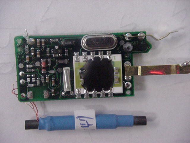
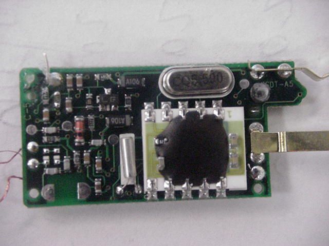
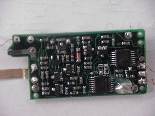
Technical Description of the Timex Corporation Wireless Heart Rate Monitor Transmitter and Watch Receiver Principle of Operation The heart rate monitor is composed of two units; a transmitter (M515) chest strap and a receiver (M818, M838, M846, M516) watch. The transmitter measures the weak electrical signal generated on the surface of the user’s skin by the beating of the heart, transforms this information into a digital format, and transmits the data to the receiver watch. A special auto power-on circuit ensures that the transmitter is only active while it is placed on a chest, so as to conserve battery power. The receiver watch receives the transmitted radio signal, decodes it, and displays the measured heart rate value on the LCD screen of the watch. The watch also functions as a full feature digital time piece. The system uses an FSK (Frequency Shift Keying) based simplex data communication scheme. The data communications rate is 1024 baud. The transmitter is operating with a carrier frequency of 139.25 KHz with a mark frequency of 137.5 KHz and a space frequency of 141.0 KHz, and the transmitting antenna is a loop type with a ferrite core. Distance and Angles The system is specified to work up to a maximum distance of 120 cm between chest strap and the watch receiver in air. The range, however, is dependant on the relative orientation between the receiver and the transmitter. Overview The M515 transmitter uses a standard EOC6008 Epson 4-bit microcontroller to measure the heartbeat, encode this information, and transmit it to the receiver. An ECG sensor circuit senses each heartbeat by measuring the voltage potential across the user’s chest. A so called auto power-on circuit allows the M515 device to conserve power by ensuring that it is only powered up when the device is placed on a chest. Three back-end circuits allow the microcontroller to transmit information to the receiver - a modulator circuit modulates the information to generate the required FSK signal; a pulse shaper circuit prepares the signal for transmission; and an antenna driver circuit handles the actual transmission. The heart rate chest strap transmitter obtains power from an internal 3.0 Vdc coin cell battery, and the receiver watch obtains power from its own internal 3.0 Vdc coin cell battery. Overall Operation of the Transmitter At the beginning of the exercise session the strap is placed on the chest. The auto power-on circuit senses this and sends a signal to the microcontroller (SENSOR_EN goes high). This signal also enables the ECG Sensor circuitry which allows heart beat pulses to be read into the microcontroller. For as long as SENSOR_EN is high, the ECG Sensor circuit will continue to send a signal to the microcontroller whenever it senses a heartbeat from the user’s chest. Each heartbeat is signaled with a positive pulse – PULSE_IN is pulsed high. For the duration of the exercise session, the microcontroller will transmit a digital data packet over the air to the watch receiver every 2 seconds. This data packet contains ID information as well as the user’s heartbeat rate. A packet transmission takes places as follows: the transmitter is first powered up by the microcontroller pulling RF_EN high, then the data line is activated by pulling DATA_OUT high, after which actual transmission commences by pulling FSK_EN high. The microcontroller may now transmit the data packet by toggling DATA_OUT high and low. After each transmission , FSK_EN is pulled low followed by DATA_OUT and lastly RF_EN. At the end of the exercise session the strap is removed and SENSOR_EN again goes low. The ECG Sensor circuitry is immediately powered down, and after the microcontroller senses the change on the SENSOR_EN line all transmitting is terminated. M515 Block Diagram Auto Power_On ECG Sensor Antenna Driver Pulse Shaper FSK Modulator (divide by 39/ divide by 40) MCU EOC6800D2E RF_EN FSK_EN SENSOR_EN PULSE_IN DATA_OUT 32.768kHz 5.5 MHz Mark Freq:137.50kHz Space Freq: 141.03kHz Ferrite Loop Antenna
ID Label/Location Info
Graphic Specs Black DIELINE-does not print Colors used: Prints 1 spot color Part Number: 991-093945 Business Group: HRM Program Name: HRM fcc label GAP Number: 981 Dieline Drawing Number: 990-093483 Vendor: Kimbells Designer/Location: ASlayton/MD File Name:991093945 Fonts used: Frutiger Black Release Date: August 15 2002 Size:refer to dieline Notes:Black ink on white opaque label sticker stock Replaces Part Number: n/a Program used: Freehand 9.0 Actual size 300% FCC: EP9TMXM515 MODEL 515 BATT. CR2032 SPLASH RESISTANT TAIWAN P:991-093945 D:990-093483 ! 0983 FCC: EP9TMXM515 MODEL 515 BATT. CR2032 SPLASH RESISTANT TAIWAN P:991-093945 D:990-093483 ! 0983
Operational Description
Technical Description of the Timex Corporation Wireless Heart Rate Monitor Transmitter and Watch Receiver Principle of Operation The heart rate monitor is composed of two units; a transmitter (M515) chest strap and a receiver (M818, M838, M846, M516) watch. The transmitter measures the weak electrical signal generated on the surface of the user’s skin by the beating of the heart, transforms this information into a digital format, and transmits the data to the receiver watch. A special auto power-on circuit ensures that the transmitter is only active while it is placed on a chest, so as to conserve battery power. The receiver watch receives the transmitted radio signal, decodes it, and displays the measured heart rate value on the LCD screen of the watch. The watch also functions as a full feature digital time piece. The system uses an FSK (Frequency Shift Keying) based simplex data communication scheme. The data communications rate is 1024 baud. The transmitter is operating with a carrier frequency of 139.25 KHz with a mark frequency of 137.5 KHz and a space frequency of 141.0 KHz, and the transmitting antenna is a loop type with a ferrite core. Distance and Angles The system is specified to work up to a maximum distance of 120 cm between chest strap and the watch receiver in air. The range, however, is dependant on the relative orientation between the receiver and the transmitter. Overview The M515 transmitter uses a standard EOC6008 Epson 4-bit microcontroller to measure the heartbeat, encode this information, and transmit it to the receiver. An ECG sensor circuit senses each heartbeat by measuring the voltage potential across the user’s chest. A so called auto power-on circuit allows the M515 device to conserve power by ensuring that it is only powered up when the device is placed on a chest. Three back-end circuits allow the microcontroller to transmit information to the receiver - a modulator circuit modulates the information to generate the required FSK signal; a pulse shaper circuit prepares the signal for transmission; and an antenna driver circuit handles the actual transmission. The heart rate chest strap transmitter obtains power from an internal 3.0 Vdc coin cell battery, and the receiver watch obtains power from its own internal 3.0 Vdc coin cell battery. Overall Operation of the Transmitter At the beginning of the exercise session the strap is placed on the chest. The auto power-on circuit senses this and sends a signal to the microcontroller (SENSOR_EN goes high). This signal also enables the ECG Sensor circuitry which allows heart beat pulses to be read into the microcontroller. For as long as SENSOR_EN is high, the ECG Sensor circuit will continue to send a signal to the microcontroller whenever it senses a heartbeat from the user’s chest. Each heartbeat is signaled with a positive pulse – PULSE_IN is pulsed high. For the duration of the exercise session, the microcontroller will transmit a digital data packet over the air to the watch receiver every 2 seconds. This data packet contains ID information as well as the user’s heartbeat rate. A packet transmission takes places as follows: the transmitter is first powered up by the microcontroller pulling RF_EN high, then the data line is activated by pulling DATA_OUT high, after which actual transmission commences by pulling FSK_EN high. The microcontroller may now transmit the data packet by toggling DATA_OUT high and low. After each transmission , FSK_EN is pulled low followed by DATA_OUT and lastly RF_EN. At the end of the exercise session the strap is removed and SENSOR_EN again goes low. The ECG Sensor circuitry is immediately powered down, and after the microcontroller senses the change on the SENSOR_EN line all transmitting is terminated. M515 Block Diagram Auto Power_On ECG Sensor Antenna Driver Pulse Shaper FSK Modulator (divide by 39/ divide by 40) MCU EOC6800D2E RF_EN FSK_EN SENSOR_EN PULSE_IN DATA_OUT 32.768kHz 5.5 MHz Mark Freq:137.50kHz Space Freq: 141.03kHz Ferrite Loop Antenna
Test Report
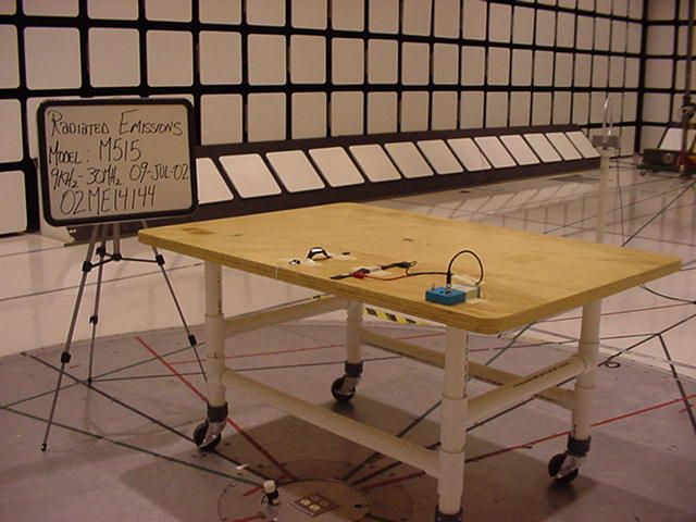
File Number: NC4557 Issued: 9/9/2002 Project Number: 02ME14144 Model Number: M515 FCC ID: EP9TMXM515 Underwriters Laboratories Inc. 1285 Walt Whitman Road Melville, New York 11747-3081 (631) 271-6200 Report of Measurements of Electromagnetic Compatibility Testing Test Report File No. : NC4557 Date of issue: 9/9/2002 Applicant : Timex Corporation Model Number M515 Product Type : Heart Rate Monitor Power Supply : 3.0 VDC (Battery) Manufacturer : Same As Applicant License holder : Same As Applicant Address : P.O Box 310 : Middlebury, CT 06762 Test Type : ⌧ Compliance Investigation Manufacturer’s Specification Test Project Number : 02ME04169 References(s) FCC ID: EP9TMXM515 Underwriters Laboratories Inc. authorizes the above-named company to reproduce this Report provided it is reproduced in its entirety. Underwriters Laboratories Inc. reports apply only to the specific samples tested under stated test conditions. It is the manufacturer's responsibility to assure that additional production units of this model are manufactured with identical electrical and mechanical components. Underwriters Laboratories Inc. shall have no liability for any deductions, inferences or generalizations drawn by the client or others from Underwriters Laboratories Inc. issued reports. This report is the confidential property of the client. As a mutual protection to our clients, the public and ourselves, extracts from the test report shall not be reproduced except in full without our written approval. This report shall not be used by the client to claim product endorsement by NVLAP or any agency of the US government. Page 1 of 15 Underwriters Laboratories Inc. 1285 Walt Whitman Rd. Melville, New York 11747 USA Tel.: 631 271-6200 Fax: 631 439-6095 Rev. No 1.0 File Number: NC4557 Issued: 9/9/2002 Project Number: 02ME14144 Model Number: M515 FCC ID: EP9TMXM515 Report Directory 1.0 G E N E R A L - Product Description.........................................................................................3 1.1 Device Configuration During Test............................................................................................................4 1.2 Deviations from ANSI C63.4....................................................................................................................4 1.3 Device Modifications Necessary for Compliance.....................................................................................5 1.4 Test Summary............................................................................................................................................5 2.0 EMISSIONS TEST REGULATIONS........................................................................................6 2.1 EUT OPERATION MODE - EMISSIONS TESTS..................................................................................6 2.1.1 Conducted Emissions Tests................................................................................................................6 2.1.2 Radiated Emissions Test (10 Meter Semi-Anechoic Chamber).........................................................7 2.2 Sample Calculation:....................................................................................................................14 3.0 SUMMARY:...............................................................................................................................15 Page 2 of 15 Underwriters Laboratories Inc. 1285 Walt Whitman Rd. Melville, New York 11747 USA Tel.: 631 271-6200 Fax: 631 439-6095 Rev. No 1.0 File Number: NC4557 Issued: 9/9/2002 Project Number: 02ME14144 Model Number: M515 FCC ID: EP9TMXM515 1.0 G E N E R A L - Product Description The Fitness System is a combination of heart rate monitor (M515) and a sports watch (M516). The heart rate monitor senses your heart rate on the chest. It calculates your heart rate and transmits it to the watch. One will simple glance at the watch display during exercise/training to make sure you are in the appropriate heart rate range this will help maintain or improve your fitness level. If set, an out of zone alarm will automatically alert you when you are not in your selected heart rate range. The Transmit antenna is permanently attached to the M515 Transmitter. Page 3 of 15 Underwriters Laboratories Inc. 1285 Walt Whitman Rd. Melville, New York 11747 USA Tel.: 631 271-6200 Fax: 631 439-6095 Rev. No 1.0 File Number: NC4557 Issued: 9/9/2002 Project Number: 02ME14144 Model Number: M515 FCC ID: EP9TMXM515 1.1 Device Configuration During Test Device Manufacturer Model Number Serial Number FCC ID Watch (Receiver) Timex M516 N/A ----------------- Body Simulator Timex HC841 Prototype ----------------- Transmitter Timex M515 17 EP9TMXM515 Cable Manufacturer Shielding Shield Bonding Type Coaxial Cable Timex Yes ---------- ----------------- Note: The EUT orientation was tested in a vertical axis, which was deemed worst-case emissions. "The results contained in this report reflect the results for this particular model and serial number. It is the responsibility of the manufacturer to ensure that all production models meet the intent of the requirements detailed within this report" Per FCC Part 2.1093 (C) this device is not required to undergo testing for radio-frequency radiation exposure. In the frequency range 9 KHz to 70 KHz inherent instrument peak noise was observed and measured. 1.2 Deviations from ANSI C63.4 ⌧ Not Applicable As described below: Page 4 of 15 Underwriters Laboratories Inc. 1285 Walt Whitman Rd. Melville, New York 11747 USA Tel.: 631 271-6200 Fax: 631 439-6095 Rev. No 1.0 File Number: NC4557 Issued: 9/9/2002 Project Number: 02ME14144 Model Number: M515 FCC ID: EP9TMXM515 1.3 Device Modifications Necessary for Compliance ⌧ N/A As described below: 1.4 Test Summary Test Basic Standard Considered Tested In Compliance Conducted Voltage Emissions FCC Subpart C, Paragraph 15.207 Yes Not applicable EUT operates on batteries N/A Radiated Emissions FCC Subpart C, Paragraph 15.209…
Text truncated - open the document above for the full version.
Contact Information
Applicant
Sam Everett(Quality Regulatory Engineer)
Technical Contact
Underwriters Laboratories Inc.Mark N Nolting
[email protected](919) 549-1584
12 Laboratory Drive · Research Triangle Park, North Carolina · United States
Non-Technical Contact
Underwriters Laboratories Inc.Mark N Nolting
[email protected](919) 549-1584
Test Firm
UL LLCRick Titus
Technical Specifications
| # | Rule Parts | Frequency Range | Power Output |
|---|---|---|---|
| 1 | 15C | 0.1375 MHz - 0.14103 MHz | - |
Other Applications from Timex Group USA, Inc.

EP9-TMXM05L
Jan 30, 2020modular
Equipment Class
DXX - Part 15 Low Power Communication Device Transmitter
EP9-TMXM05J
Jan 30, 2020modular
Equipment Class
DXX - Part 15 Low Power Communication Device Transmitter
EP9-TMXM372
Sep 18, 2015Timex Metropolitan+
Equipment Class
DTS - Digital Transmission System
EP9-TMXM053
Feb 18, 2015M053 - Ironman Classic 50 Move+
Equipment Class
DSS - Part 15 Spread Spectrum Transmitter
EP9-TMXM049
Feb 18, 2015M049 - Ironman Classic 50 Move+
Equipment Class
DSS - Part 15 Spread Spectrum Transmitter