EP9TMXM597Pedometer
Timex Group USA, Inc.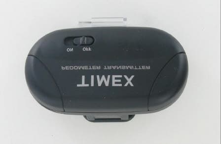
Click to zoom
Application Details
- Equipment Class
- DCD - Part 15 Low Power Transmitter Below 1705 kHz
- Date of Grant
- Apr 13, 2006
- Application Purpose
- Original Equipment
- Date of Application
- Apr 13, 2006
- Equipment Note
- Pedometer
- Frequency Range
- 0.13800000 - 0.14100000
- Company
- Timex Group USA, Inc.
- Country
- United States
Documents & Files
Document Text
Text extracted from the exhibit documents filed with the FCC. Open a document above to read the original.
Users Manual
1 TIMEX ® DIGITAL FITNESS SYSTEMRegister your product at www.timex.comThe Timex® Digital Fitness System incorporates the very latest digital technolo-gy from Timex with methodologies used by fitness experts and personal train-ers. As the world leader in sports timing devices, Timex has created a fitnesssystem that combines the digital accuracy demanded by world-class athleteswith features anyone at any age can use to stay “fit for life.”Note: This manual may describe features or functions that are not available on all models. A digital heart rate sensor may be purchased separately. Resources on the InternetThe Timex web site (www.timex.com) is an excellent source of information to help you get more out of your Timex® Digital Fitness System:www.timex.com/hrm - Information on Timex Digital Heart Rate Monitors, including product feature listings and simulations.www.timex.com/fitness - Fitness and training tips using the Timex Digital Heart Rate Monitors.Note: Always consult your physician before beginning or modifying an exercise program. W226_M597_book.qxd 3/10/06 12:09 PM Page 1 ©2006 Timex Corporation. TIMEX is a registered trademark of Timex Corporation. INDIGLO is a registered trademark of Indiglo Corporation in the US and other countries. W226-NA 597 095000 page 1 page 0? página 0? página 0 EnglishFrançaisEspañolPortuguês digital fitness system guide Digital Fitness System W226_M597_PED_COV_NA.qxd 3/8/06 1:09 PM Page 1 3 OVERVIEW DIGITAL FITNESS SYSTEM FEATURESWatch• Time with 12-hour (AM/PM) or 24-hour format • Day, month and date with Month/Date or Date/Month format • Optional hourly chime • 24-hour chronograph with Lap or Split time • 99-lap counter • Daily alarm with 5-minute backup • INDIGLO® night-light Pedometer System• Step counter (0 - 999,999) with step goal feature • Distance traveled (miles or kilometers) • Automatic activity timer • Calories burned • Speed (miles or kilometers per hour) • Step rate (steps per minute) Heart Rate Monitor(with Optional Digital Heart Rate Sensor)• Continuous heart rate • Average heart rate during activity 2 WATCH (RECEIVER) PEDOMETER (TRANSMITTER) DIGITAL HEART RATE SENSOR (OPTIONAL) W226_M597_book.qxd 3/10/06 12:09 PM Page 2 5 SETTING TIME AND DATETo set time, date, and options:1) With time and date showing, press and hold SET. 2) Hour flashes. Press START·SPLIT to change Hour (including AM/PM); hold button to scan values. 3) Press MODE. Minutes flash. Press START·SPLIT to change Minutes.4) Press MODE. Seconds flash. Press START·SPLIT to set Seconds to zero.5) Press MODE. Month flashes. Press START·SPLIT to change Month.6) Press MODE. Day flashes. Press START·SPLIT to change Day.7) Press MODE. Year flashes. Press START·SPLIT to change Year.8) Press MODE to set options. Press START·SPLIT to change value and then press MODE to go to next option. Available options are: • Time: 12-hour (AM/PM) or 24-hour format.• Date: MM-DD (Month/Day) or DD.MM (Day/Month) date format.• Chime: When chime is on, N appears and watch beeps on every hour. • Beep: The watch beeps for all button presses.9) Press SET at any step to save your settings and exit to Time.CHRONOGRAPHThis mode provides a chronograph (stopwatch) function. Press MODE repeatedlyuntil CHRONO appears.Watch will display lap or split times; their differences are explained in the following diagrammed example. WATCH FUNCTIONSBASIC OPERATION (Button functions during setting are shown in parentheses) Press MODE repeatedly to step through the modes: Time, Pedometer, Heart RateMonitor (appears when optional heart rate sensor is worn), Chronograph, Alarm,and Setup. Press MODE to exit the current mode and return to Time mode.4 INDI G LO ® BUTTON SETSTOP • RESET (DONE) MODE (NEXT STEP) RE C EIVER ON START • SPLIT (IN C REASE VALUE) W226_M597_book.qxd 3/10/06 12:09 PM Page 4 7 ALARMWatch has a daily alarm. Press MODE repeatedly until ALARM appears.To set alarm:1) Press and hold SET. 2) Hour flashes. Press START·SPLIT to change Hour (including AM/PM); hold button to scan values. 3) Press MODE. Minutes flash. Press START·SPLIT to change Minutes.4) Press SET, at any step, when done to save settings.To turn alarm ON/OFF, press START·SPLIT.When Alarm is ON, alarm clock icon a appears in this mode and in Time mode. When the Alarm sounds, the INDIGLO® night-light flashes. Press any button tosilence the Alarm. If no button is pressed, the Alarm will sound for 20 secondsand sound again five minutes later.Alarm repeats daily unless turned OFF.INDIGLO® NIGHT-LIGHTPress INDIGLO® button to illuminate watch display for 3 seconds. Patented(U.S. pat. 4,527,096 and 4,775,964) electroluminescent technology used in theINDIGLO® night-light illuminates watch display at night and in low light condi-tions. When the Chrono is reset (00.00.00), press STP·RST to switch between lap andsplit times. LAP or SPL will be displayed.To start, press START·SPLIT. Chrono counts up by hundredths of a second up toone hour, then by seconds up to 24 hours. The stopwatch icon w flashes to indi- cate that the Chrono is running.To stop, press STP·RST. The stopwatch icon w stops flashing to indicate the Chrono is stopped. To resume, press START·SPLIT, or to reset (clear) Chrono,press and hold STP·RST. While the Chrono is running, press START·SPLIT to take a lap or split. Lap num-ber and lap or split time is displayed while the Chrono continues to run. After 10seconds, the display of the running Chrono appears, or press MODE to displayimmediately.Chrono continues to run, even if you exit the Chrono mode. Stopwatch icon w appears in Time mode if the Chrono is running.6 LAP 1 = 7.11 LAP 2 = 7.50 SPLIT 2 = 15.01 LAP 3 = 7.08 SPLIT 3 = 22.09 LAP 4 = 7.30 SPLIT 4 = 29.39 SPLIT 1 = 7.11 W226_M597_book.qxd 3/10/06 12:09 PM Page 6 9 1) GOAL - the number of steps you want to take daily • Press START SPLIT to change value of each digit and press MODE to go to the next digits. Press MODE to go to: 2) STRIDE - the length of each step or stride • Stride unit flashe…
Text truncated - open the document above for the full version.
External Photos
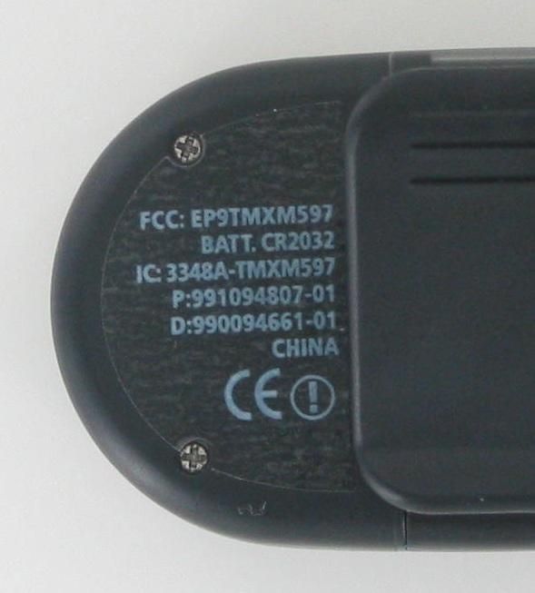
External photos FCC ID: EP9TMXM597 Front Back External photos FCC ID: EP9TMXM597 Left side Right side
Internal Photos
Internal photos FCC ID: EP9TMXM597 PCB processor side PCB opposite side Antenna
Test Report
Report Number 3082770BOX.006 Page 2 of 15 1.0 Job Description 1.1 Client Information This EUT has been tested at the request of: Company: Timex Communication 555 Christian Road PO Box 310 Middlebury, CT 06762-0310 Contact: John Davino Telephone: Fax: Email: 203-346-4340 203-346-7146 [email protected] 1.2 Equipment Under Test Equipment Type: Pedometer Model Number(s): M597 Serial number(s): QCE6483 Manufacturer: Timex Communication EUT receive date: 02/23/2006 EUT received condition: Prototype in good condition Test start date: 03/01/2006 Test end date: 03/06/2006 1.3 Test Plan Reference: Tested according to the standards listed and ANSI C63.4:2003. 1.4 Test Configuration 1.4.1 Block Diagram Turntable EUT Report Number 3082770BOX.006 Page 3 of 15 1.4.2. Cables: Cable Shielding Connector Length (m) Qty. No cables 1.4.3. Support Equipment: Name: Model No.: Serial No.: No support equipment 1.5 Mode(s) of Operation: The EUT was activated from a fresh 3 Volt battery for all testing except for the frequency stability test, which used a DC power supply to vary the input power around 3 VDC. During testing, the EUT was programmed to transmit in a continuous fashion. The EUT was investigated in 3 orthogonal axes. Report Number 3082770BOX.006 Page 4 of 15 2.0 Test Summary TEST STANDARD RESULTS FCC Part 15 Subpart C 15.209 SUB-TEST TEST PARAMETER COMMENT RF Output Power and Spurious Emissions Below 30 MHz FCC 15.205, 15.209 Emissions must be below the 15.209 limits. Pass Occupied Bandwidth There is no bandwidth requirement. Pass Spurious Emissions Above 30 MHz FCC 15.205, 15.209 Emissions must be below the 15.209 limits. Pass Notes: The EUT transmits at 137.5 and 141 kHz. REVISION SUMMARY – The following changes have been made to this Report: Date Project No. Project Handler Page(s) Item Description of Change Report Number 3082770BOX.006 Page 5 of 15 3.0 Sample Calculations The field strength is calculated by adding the Antenna Factor and Cable Factor, and subtracting the Amplifier Gain (if any) from the measured reading. The basic equation with a sample calculation is as follows: FS = RA + AF + CF - AG Where FS = Field Strength in dBμV/m RA = Receiver Amplitude (including preamplifier) in dBμV CF = Cable Attenuation Factor in dB AF = Antenna Factor in dB AG = Amplifier Gain in dB In the following table(s), the reading shown on the data table reflects the preamplifier gain. An example for the calculations in the following table is as follows. Assume a receiver reading of 52.0 dBμV is obtained. The antenna factor of 7.4 dB and cable factor of 1.6 dB is added. The amplifier gain of 29 dB is subtracted, giving a field strength of 32 dBμV/m. This value in dBμV/m was converted to its corresponding level in μV/m. RA = 52.0 dBμV AF = 7.4 dB/m CF = 1.6 dB AG = 29.0 dB FS = 32 dBμV/m Level in μV/m = [10( 32 dBμV/m)/20] = 39.8 μV/m The following is how net line-conducted readings were determined: NF = RF + LF + CF + AF Where NF = Net Reading in dBμV RF = Reading from receiver in dBμV LF = LISN Correction Factor in dB CF = Cable Correction Factor in dB AF = Attenuator Loss Factor in dB To convert from dBμV to μV or mV the following was used: UF = 10 (NF / 20) where UF = Net Reading in μV Example: NF = RF + LF + CF + AF = 28.5 + 0.2 + 0.4 + 20.0 = 49.1 dBμV UF = 10 (48.1 dBμV / 20) = 254 μV/m Report Number 3082770BOX.006 Page 6 of 15 3.1 Measurement Uncertainty Compliance of the product is based on the measured value. However, the measurement uncertainty is included for informational purposes. The expanded uncertainty (k = 2) for radiated emissions from 30 to 1000 MHz has been determined to be: ±3.5 dB at 10m, ±3.8 dB at 3m The expanded uncertainty (k = 2) for mains conducted emissions from 150 kHz to 30 MHz has been determined to be: ±2.6 dB The expanded uncertainty (k = 2) for telecom port conducted emissions from 150 kHz to 30 MHz has been determined to be: ±3.2 for ISN and voltage probe measurements ±3.1 for current probe measurements Report Number 3082770BOX.006 Page 7 of 15 3.2 Site Description Test Site(s): 2 Our OATS are 3m and 10m sheltered emissions measurement ranges located in a light commercial environment in Boxborough, Massachusetts. They meet the technical requirements of ANSI C63.4-2003 and CISPR 22:1993/EN 55022:1994 for radiated and conducted emission measurements. The shelter structure is entirely fiberglass and plastic, with outside dimensions of 33 ft x 57 ft. The structure resembles a quonset hut with a center ceiling height of 16.5 ft. The testing floor is covered by a galvanized sheet metal groundplane that is earth-grounded via copper rods around the perimeter of the site. The joints between individual metal sheets are bridged with a 2 inch wide metal strips to provide low RF impedance contact throughout. The sheets are screwed in place with stainless steel, round-head screws every three inches. Site illumination and HVAC are provided from beneath the ground reference plane through flush entry ports, the port covers are electrically bonded to the ground plane. A flush metal turntable with 12 ft. diameter and 5000 lb. load capacity (12,000 lb. in Site 3) is provided for floor-standing equipment. A wooden table 80 cm high is used for table-top equipment. The turntable is electrically connected to the ground plane with three copper straps. The straps are connected to the turntable at the center of it with ground braid. The copper strap is directly connected to the groundplane at the edges of the turntable. The turntable is located on the south end of the structure and the antennas are mounted 3 and 10 meters away to the north. The antenna mast is a non-conductive with remote control of antenna height and polarization. The antenna height is adjustable from 1 to 4 meters. All final radiated emission measurements are performed with the testing personnel and measurement equipment located below the ground reference plane. The site has a full basement underneath the turntable where support equip…
Text truncated - open the document above for the full version.
Test Setup Photos
Report Number 3082770BOX.006 Page 14 of 15 Setup Photos Report Number 3082770BOX.006 Page 15 of 15
Contact Information
Applicant
Sam Everett(Quality Regulatory Engineer)
Technical Contact
Timex CorporationRon DeRosa
[email protected]203-346-4333
555 Christian Road · Middlebury, Connecticut · United States
Non-Technical Contact
Timex CorporationBrian Hudson
[email protected]2-3-346-5321
Test Firm
Intertek Testing Services NA Inc.Roland Gubisch
Technical Specifications
| # | Rule Parts | Frequency Range | Power Output |
|---|---|---|---|
| 1 | 15C | 0.138 MHz - 0.141 MHz | - |
Other Applications from Timex Group USA, Inc.

EP9-TMXM05L
Jan 30, 2020modular
Equipment Class
DXX - Part 15 Low Power Communication Device Transmitter
EP9-TMXM05J
Jan 30, 2020modular
Equipment Class
DXX - Part 15 Low Power Communication Device Transmitter
EP9-TMXM372
Sep 18, 2015Timex Metropolitan+
Equipment Class
DTS - Digital Transmission System
EP9-TMXM053
Feb 18, 2015M053 - Ironman Classic 50 Move+
Equipment Class
DSS - Part 15 Spread Spectrum Transmitter
EP9-TMXM049
Feb 18, 2015M049 - Ironman Classic 50 Move+
Equipment Class
DSS - Part 15 Spread Spectrum Transmitter