EP9TMXM640Heart Rate Monitor
Timex Group USA, Inc.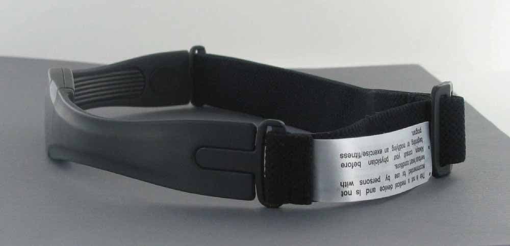
Click to zoom
Application Details
- Equipment Class
- DCD - Part 15 Low Power Transmitter Below 1705 kHz
- Date of Grant
- Dec 13, 2006
- Application Purpose
- Original Equipment
- Date of Application
- Dec 13, 2006
- Equipment Note
- Heart Rate Monitor
- Frequency Range
- 0.13800000 - 0.14100000
- Company
- Timex Group USA, Inc.
- Country
- United States
Documents & Files
Document Text
Text extracted from the exhibit documents filed with the FCC. Open a document above to read the original.
Users Manual
1 Heart Rate Sensor Speed + Distance Sensor Watches are for more than keeping time. Digital technology givesyour watch the ability to display your heart rate or measure yourspeed and distance traveled. These functions require the use ofexternal sensors that transmit information wirelessly to yourwatch. This booklet provides instructions for properly setting up,operating and maintaining these devices. Look for the section thatis appropriate for the type of device you have.Register your product at www.timex.comFor information on using your watch, consultthe watch instruction booklet. Timex ® Fitness Sensors W184_NA_Rev.03.qxd 11/1/06 11:24 AM Page 1 3 3. Start the Heart Rate Monitor: Refer to the user manual for your watch for detailed instructions on viewing heart rate data. WarningThis is not a medical device and is not recommended for useby persons with serious heart conditions. You should alwaysconsult your physician before beginning or modifying anexercise program.Interference with the radio signal, poor contact between your skinand the chest strap, and other factors may prevent accurate transmission of heart rate data.MaintenanceRinse Heart Rate Sensor and strap in fresh water to avoid build up ofmaterials that can interfere with the measurement of your heart rate.Transmitter Battery Life and ReplacementBattery life of the transmitter should exceed two years, basedupon using it an hour a day. Greater usage will shorten the batterylife. Replace transmitter battery when any of the following occur:• The watch no longer receives heart rate information from the chest transmitter when properly worn on the chest. • Error messages (COMM ERR, SIGNAL LOST) appear with increased frequency on the display. Heart Rate MonitorHow the Digital Heart Rate Monitor WorksThe Heart Rate Monitor is a combination of a Heart Rate Sensor and a sport watch. The Heart Rate Sensor attaches to your chest and measures the electrical signals generated by the heart as it isbeating. Using this information, it then calculates your heart rateand transmits it to your watch. You simply glance at the watch during exercise/training to make sure you are in the appropriateheart rate range to maintain or improve your fitness level.How to Use the Digital Heart Rate Monitor1. Wet the Heart Rate Sensor pads with tap water. If necessary, use a heart rate monitor Electrode Gel for better contact. Goodcontact between the skin and the sensorpads is ESSENTIAL for proper operationof the Heart Rate Monitor. 2. Put on the chest strap. Fasten the strap snugly around your chest, just below the breasts. Be sure the transmitter iscentered on the chest and is right sideup so the logo can be read by someonefacing you. 2 Sensor Pads W184_NA_Rev.03.qxd 11/1/06 11:24 AM Page 2 5 Water ResistanceThe Heart Rate Sensor withstands water pressure to 60 p.s.i. Seechart at end of booklet for equivalents. WARNING: The Heart Rate Sensor will not display heart rate when operated under water.Speed + Distance SensorHow the Speed and Distance System WorksThe Speed + Distance (S+D) Sensor acquires signals from orbitingGPS (Global Positioning System) satellites to determine your positionand changes in position anywhere on the globe. This informationis transmitted wirelessly to your watch so that it can computeyour speed, pace and distance traveled. For additional informationon determining your speed and distance, see the instructions foryour watch.About GPS Lock Times• On first use, the S+D Sensor can take up to 5 minutes or even longer to establish a link with the satellites. After that, the unittypically needs only one minute. • If you move hundreds of miles from the location where you last used the S+D Sensor or if you leave the S+D Sensor powered upindoors for long periods of time before going outdoors, thesearch may take longer than expected. Battery ReplacementNOTE: You’ll need to have a device (such as a watch) capableof displaying heart rate information to verify that the newbattery has been inserted correctly. Use a coin to open thebattery compartment cover (back of sensor).• Insert new battery (CR2032 or equivalent) with “ + ” facing you. • Push the reset button next to the battery. Use a toothpick or straightened paper clip. • Reinstall battery cover.• Perform quick test of the unit: 1. Move away from sources of electrical or radio interference.2. Liberally moisten the Heart Rate Sensor pads and put the chest strap around your chest, securely against your skin. 3. Activate the heart rate monitor function on the watch.4. Within a few seconds, the heart symbol on the watch display should begin flashing, indicating that the sensor is active. Thisconfirms that the battery was installed correctly.NOTE: A heart rate value does not need to appear on the display during this test. IF FLASHING HEART DOES NOT APPEAR ON WATCH:• Press the reset switch in the battery compartment again and replace the battery cover. • Reinstall the battery, and repeat test procedure above. 4 W184_NA_Rev.03.qxd 11/1/06 11:24 AM Page 4 • The S+D Sensor will shut itself off automatically if any of the following events occur: — The battery becomes exhausted.— No motion is detected for 15 consecutive minutes.— No GPS signals are detected for 15 consecutive minutes. Wearing the Speed and Distance S+D SensorFor best results, strap the S+D Sensor to your upper arm. You mayalso clip it to your waist. Wear your watch so it is always within 1 meter (about 3 feet) of the S+D Sensor. Be sure the sensor isright side up so the GPS logo can be read by someone facing you. 7 S+D Sensor ON/OFFRemovable Arm Band Battery Hatch • For shortest GPS lock times, try to minimize movement while the indicator light is flashing red. Operating the S+D SensorFor best results, the Sensor needs a clear view of the sky.• Press and hold the S+D SENSOR ON/OFF button to turn on the receiver. You should be outdoors in an open area. If the buttonlight glows red immediately (continuously, not flashing), the bat-tery is e…
Text truncated - open the document above for the full version.
External Photos
Timex HRM system - M640 strap with M685 watch (external) M640 hrm strap front (external) M640 hrm strap left side (external) M640 hrm strap right side (external) M640 hrm strap left side (external)
ID Label/Location Info
M640 hrm strap left side (external)
Internal Photos
Internal Photograph cover removed Internal Photograph Cover removed - zoom Internal Photograph main board Internal Photograph main board
Test Report
Report Number 3104393BOX.001a Page 2 of 35 1.0 Job Description 1.1 Client Information This EUT has been tested at the request of: Company: Timex Corporation 555 Christian Road PO Box 310 Middlebury, CT 06762-0310 Contact: John Davino Telephone: Fax: Email: 203-346-4340 203-346-7146 [email protected] 1.2 Equipment Under Test Equipment Type: HRM Chest Strap Model Number(s): M640 Serial number(s): 6 Manufacturer: Timex Corporation EUT receive date: 09/12/2006 EUT received condition: Prototype in good condition Test start date: 09/13/2006 Test end date: 10/17/2006 1.3 Test Plan Reference: Tested according to the standards listed, ANSI C63.4:2003, ERC/REC 70-03 November 2005, RSS-Gen Issue 1 September 2005, New Zealand Radiocommunications Notice 2005 No. 2, and ETSI EN 300 330-1 V1.3.2 (2002-12). 1.4 Test Configuration 1.4.1 Block Diagram Turntable EUT Signal Generator Report Number 3104393BOX.001a Page 3 of 35 1.4.2. Cables: Cable Shielding Connector Length (m) Qty. DC Power Cables None Wire 0.15 2 Signal Generator Cable Coaxial BNC to 2-wire DC 0.3 1 1.4.3. Support Equipment: Name: Model No.: Serial No.: HRM Signal Generator HRM Generator N/L Name: Model No.: Serial No.: Lambda DC Power Supply LQD-423 C96143 Name: Model No.: Serial No.: Timex Fitness HRM Wristwatch 686-5J0410 N/L 1.5 Mode(s) of Operation: The EUT was activated from a fresh 3 Volt battery for all testing except for the frequency stability test, which used a DC power supply to vary the input power around 3 VDC. The EUT was investigated in 3 orthogonal axes. The Signal Generator support equipment was connected to the sensor pads on the EUT via alligator clips which delivered a 2 Hz signal to the device. This caused the EUT to transmit a typical signal on a 2 second interval. The watch receiver was used to verify continuing transmission via the display which showed the Beats Per Minute (BPM) value that the EUT transmitted, 120 BPM for the 2 Hz signal input. 1.5a EUT Cycle Time:_2 Seconds __ 1.6 Monitoring of Sample: The EUT was monitored via the watch receiver display which showed the BPM value which was detected by the EUT and transmitted to the watch receiver. Report Number 3104393BOX.001a Page 4 of 35 1.7 Sample Performance Criteria: EN 55024 Performance Criteria Criterion A: The EUT must not be affected by the test disturbance. Criterion B: The EUT may be affected by the test disturbance, but must resume normal operation when the test disturbance is removed. Criterion C: The EUT may be affected by the test disturbance and may require operator intervention to resume normal operation. Per Clause 6.1 of ETSI EN 301 489-1 V1.6.1 (2005-09) During and after the test, the apparatus shall continue to operate as intended. No degradation of performance or loss of function is allowed below a permissible performance level specified by the manufacturer when the apparatus is used as intended. During the test the EUT shall not unintentionally transmit or change its actual operating state and stored data. Since the EUT is used for fitness purposes and not medical diagnostics, small errors in the Beats Per Minute value would be insignificant, and large variations would be obvious to the user as an erroneous result. 1.8 Floor Standing Equipment: Applicable:____ Not Applicable:_X _ For floor standing equipment, 40cm RFI field uniformity data is located in the chamber equipment folder. Report Number 3104393BOX.001a Page 5 of 35 2.0 Test Summary TEST STANDARD AS/NZS 4268:2003 CENELEC EN 55022:1998 & CENELEC EN 55024:1998 ETSI EN 300 330-1 V1.3.2 (2002-12) & ETSI EN 300 330-2 V1.2.1 (2004-11) ETSI EN 301 489-1 V1.6.1 (2005-09) & ETSI EN 301 489-3 V1.4.1 (2002-08) FCC Part 15 Subpart C 15.209 Industry Canada RSS-210 Issue 6 September 2005 SUB-TEST TEST PARAMETER NOTE AS/NZS 4268 ETSI EN 300 330-1 ETSI EN 300 330-2 FCC Part 15 Subpart C Industry Canada RSS-210 RF Output Power and Spurious Emissions Below 30 MHz AS/NZS 4268 5.4, 8.2 ETSI EN 300 330-1 7.2, 7.4 ERC/REC 70-03 Annex 9 FCC 15.205, 15.209 IC RSS-210 2.7 AS/NZS: The fundamental field strength must not exceed 3 uW (18.5 dBuA/m at 3m) in Australia and 10 mW in New Zealand. The spurious emissions must not exceed 0.1 uW (-40 dBm) in Australia and 2.25 uW in New Zealand. ETSI: The fundamental field strength at 137.5 kHz must not exceed 73.4 dBuA/m (ERC/REC 70-03) or 46.6 dBuA/m and the fundamental field strength at 141 kHz must not exceed 69.1 dBuA/m (ERC/REC 70-03) or 46.5 dBuA/m at 3 meters. The field strength of spurious emissions must not exceed 27 dBuA/m at 9 kHz descending 3 dB/Octave at 10 meters. FCC: Emissions must be below the 15.209 limits. IC: Emissions must be below the RSS-210 2.7 Table 3 limits. Pass Spurious Emissions Above 30 MHz AS/NZS 4268 8.2 ETSI EN 300 330-1 7.4 FCC 15.205, 15.209 IC RSS-210 2.7 AS/NZS: The spurious emissions must not exceed 0.1 uW (-40 dBm) in Australia and 2.25 uW in New Zealand. ETSI: The spurious emissions must not exceed 250 nW (-36.0 dBm), except in the ranges from 47-74, 87.5-118, 174-230, and 470-862 MHz, where the limit is 4 nW (-54.0 dBm). FCC: Emissions must be below the 15.209 limits. IC: Emissions must be below the RSS-210 2.7 Table 2 limits. Pass Occupied Bandwidth AS/NZS 4268 8.3 FCC 15.215 IC RSS-Gen 4.4.1 There is no limit on bandwidth. Pass Operating Frequencies/ Permitted Frequency Range of the Modulation Bandwidth AS/NZS 4268 8.4 ETSI EN 300 330-1 7.3 AS/NZS: The fundamental emissions must remain within the band from 70 kHz to 160 kHz in Australia and between 30 kHz and 190 kHz in New Zealand. ETSI: The fundamental emissions must remain within the assigned frequency band. Pass CENELEC EN 55022:1998 ETSI EN 301 489-1 V1.6.1 (2005-09) ETSI EN 301 489-3 V1.4.1 (2002-08) Emissions Radiated Emissions Emissions below specified limits Pass CENELEC EN 55024:1998 ETSI EN 301 489-1 V1.6.1 (2005-09) ETSI EN 301 489-3 V1.4.1 (2002-08) Immunity EN 61000-4-2:1995 Electrostatic Discharge (ESD) ±4kV Contact discharge and ±8kV Air discharge Pass EN 610…
Text truncated - open the document above for the full version.
Test Setup Photos
Report Number 3104393BOX.001a Page 16 of 35 Setup Photos Radiated Emissions, 150 kHz – 30 MHz Report Number 3104393BOX.001a Page 17 of 35 Radiated Emissions, 150 kHz – 30 MHz Report Number 3104393BOX.001a Page 24 of 35 Setup Photos Report Number 3104393BOX.001a Page 25 of 35
Contact Information
Applicant
Sam Everett(Quality Regulatory Engineer)
Technical Contact
Timex CorporationRonald DeRosa
[email protected]203-346-4333
555 Christian Road · Middlebury, Connecticut · United States
Non-Technical Contact
TimexBrian Hudson
[email protected]203-346-5321
Test Firm
Intertek Testing Services NA Inc.Yaqing Liu
[email protected]978 635 8662
Technical Specifications
| # | Rule Parts | Frequency Range | Power Output |
|---|---|---|---|
| 1 | 15C | 0.138 MHz - 0.141 MHz | - |
Other Applications from Timex Group USA, Inc.

EP9-TMXM05L
Jan 30, 2020modular
Equipment Class
DXX - Part 15 Low Power Communication Device Transmitter
EP9-TMXM05J
Jan 30, 2020modular
Equipment Class
DXX - Part 15 Low Power Communication Device Transmitter
EP9-TMXM372
Sep 18, 2015Timex Metropolitan+
Equipment Class
DTS - Digital Transmission System
EP9-TMXM053
Feb 18, 2015M053 - Ironman Classic 50 Move+
Equipment Class
DSS - Part 15 Spread Spectrum Transmitter
EP9-TMXM049
Feb 18, 2015M049 - Ironman Classic 50 Move+
Equipment Class
DSS - Part 15 Spread Spectrum Transmitter